EP1535684A2 - Handbetätigte Steuervorrichtung für eine Drahtfunkenschneidmaschine - Google Patents
Handbetätigte Steuervorrichtung für eine Drahtfunkenschneidmaschine Download PDFInfo
- Publication number
- EP1535684A2 EP1535684A2 EP04257312A EP04257312A EP1535684A2 EP 1535684 A2 EP1535684 A2 EP 1535684A2 EP 04257312 A EP04257312 A EP 04257312A EP 04257312 A EP04257312 A EP 04257312A EP 1535684 A2 EP1535684 A2 EP 1535684A2
- Authority
- EP
- European Patent Office
- Prior art keywords
- axis
- feed
- time
- key
- jog
- Prior art date
- Legal status (The legal status is an assumption and is not a legal conclusion. Google has not performed a legal analysis and makes no representation as to the accuracy of the status listed.)
- Withdrawn
Links
- 238000003860 storage Methods 0.000 claims description 2
- 238000012840 feeding operation Methods 0.000 abstract description 2
- 238000003754 machining Methods 0.000 description 6
- 238000005259 measurement Methods 0.000 description 3
- 238000000034 method Methods 0.000 description 3
- 238000010586 diagram Methods 0.000 description 2
- 239000004973 liquid crystal related substance Substances 0.000 description 1
- 238000002360 preparation method Methods 0.000 description 1
- 238000003825 pressing Methods 0.000 description 1
Images

Classifications
-
- B—PERFORMING OPERATIONS; TRANSPORTING
- B23—MACHINE TOOLS; METAL-WORKING NOT OTHERWISE PROVIDED FOR
- B23H—WORKING OF METAL BY THE ACTION OF A HIGH CONCENTRATION OF ELECTRIC CURRENT ON A WORKPIECE USING AN ELECTRODE WHICH TAKES THE PLACE OF A TOOL; SUCH WORKING COMBINED WITH OTHER FORMS OF WORKING OF METAL
- B23H7/00—Processes or apparatus applicable to both electrical discharge machining and electrochemical machining
- B23H7/02—Wire-cutting
-
- B—PERFORMING OPERATIONS; TRANSPORTING
- B23—MACHINE TOOLS; METAL-WORKING NOT OTHERWISE PROVIDED FOR
- B23H—WORKING OF METAL BY THE ACTION OF A HIGH CONCENTRATION OF ELECTRIC CURRENT ON A WORKPIECE USING AN ELECTRODE WHICH TAKES THE PLACE OF A TOOL; SUCH WORKING COMBINED WITH OTHER FORMS OF WORKING OF METAL
- B23H7/00—Processes or apparatus applicable to both electrical discharge machining and electrochemical machining
- B23H7/02—Wire-cutting
- B23H7/04—Apparatus for supplying current to working gap; Electric circuits specially adapted therefor
-
- B—PERFORMING OPERATIONS; TRANSPORTING
- B23—MACHINE TOOLS; METAL-WORKING NOT OTHERWISE PROVIDED FOR
- B23H—WORKING OF METAL BY THE ACTION OF A HIGH CONCENTRATION OF ELECTRIC CURRENT ON A WORKPIECE USING AN ELECTRODE WHICH TAKES THE PLACE OF A TOOL; SUCH WORKING COMBINED WITH OTHER FORMS OF WORKING OF METAL
- B23H7/00—Processes or apparatus applicable to both electrical discharge machining and electrochemical machining
- B23H7/02—Wire-cutting
- B23H7/06—Control of the travel curve of the relative movement between electrode and workpiece
- B23H7/065—Electric circuits specially adapted therefor
-
- B—PERFORMING OPERATIONS; TRANSPORTING
- B23—MACHINE TOOLS; METAL-WORKING NOT OTHERWISE PROVIDED FOR
- B23H—WORKING OF METAL BY THE ACTION OF A HIGH CONCENTRATION OF ELECTRIC CURRENT ON A WORKPIECE USING AN ELECTRODE WHICH TAKES THE PLACE OF A TOOL; SUCH WORKING COMBINED WITH OTHER FORMS OF WORKING OF METAL
- B23H7/00—Processes or apparatus applicable to both electrical discharge machining and electrochemical machining
- B23H7/26—Apparatus for moving or positioning electrode relatively to workpiece; Mounting of electrode
- B23H7/28—Moving electrode in a plane normal to the feed direction, e.g. orbiting
-
- B—PERFORMING OPERATIONS; TRANSPORTING
- B23—MACHINE TOOLS; METAL-WORKING NOT OTHERWISE PROVIDED FOR
- B23H—WORKING OF METAL BY THE ACTION OF A HIGH CONCENTRATION OF ELECTRIC CURRENT ON A WORKPIECE USING AN ELECTRODE WHICH TAKES THE PLACE OF A TOOL; SUCH WORKING COMBINED WITH OTHER FORMS OF WORKING OF METAL
- B23H9/00—Machining specially adapted for treating particular metal objects or for obtaining special effects or results on metal objects
- B23H9/12—Forming parts of complementary shape, e.g. punch-and-die
Definitions
- the present invention relates to a wire electric discharge machine, and in particular to a manual feeding device for feeding axes manually to move a workpiece relatively to a wire electrode.
- a wire electric discharge machine machines a workpiece by relatively moving the workpiece to a wire electrode stretched and applying a voltage between the wire electrode and the workpiece to cause electric discharge between the wire electrode and the workpiece.
- the workpiece is relatively moved to the machining electrode according to a machining program.
- the workpiece or the electrode needs to be moved by manual operation.
- X and Y axes for moving a table (workpiece) in X-axis and Y-axis directions
- a Z axis for moving an upper guide in a Z-axis direction perpendicular to the X and Y axes
- U and V axes for moving the upper guide in the X-axis and Y-axis directions.
- axis motion keys for the X, Y, Z, U and Z axes are operated to move the axes in the axis directions corresponding to the keys operated.
- the manual operation includes a jog feed in which an axis is driven continuously while an axis motion key is operated, and a step feed in which an axis is moved by a predetermined amount each time an axis motion key is operated.
- the jog feed is used to place an axis roughly in an intended position, while the step feed is used to place an axis exactly in an intended position.
- Selection between the jog feed and the step feed is made by a selection switch.
- the jog feed mode is selected and an axis motion key is operated, the workpiece is relatively moved to the wire electrode in an axis direction corresponding to the operated axis motion key at a predetermined speed.
- the step feed is selected and an axis motion key is operated, the workpiece is moved relatively to the wire electrode by a predetermined amount.
- the present invention enables selection between a jog feed and a step feed to be automatically made in accordance with an operator's intension without need of mode change.
- a manual feeding device of the present invention is provided in a wire electric discharge machine having a manual operation key for manually providing motion of an axis of the wire electric discharge machine.
- the manual feeding device comprises: measuring means for measuring a continuing time period of an on-state of the manual operation key; determining means for determining whether or not the continuing time period measured by the measuring means exceeds a predetermined time length; step-feeding means for providing motion of the axis by a set amount when it is determined that the continuing time period terminates within the predetermined time length by the determining means; and jog-feeding means for providing motion of the axis at a set speed until the on-state of the manual operation key is discontinued, when it is determined that the continuing time period exceeds the predetermined time length by the determining means.
- the jog feeding means may comprise means for switching the set speed for a higher set speed in accordance with length of the continuing time period measured by the measuring means.
- the predetermined time length may be given by a parameter stored in parameter storage means.
- FIG. 1 is a block diagram showing relevant elements of an embodiment of the present invention.
- a manual feeding device in this embodiment is formed of a control device for controlling a wire electric discharge machine and software.
- FIG. 1 shows only the elements relevant to the present invention.
- a memory 12 formed of ROM, RAM, etc.
- a display device 13 such as a liquid crystal display or a CRT display
- a keyboard 14 an I/O unit 15 connected to a control panel 20
- axis control circuits 16 for feed axes X, Y, Z, U and V of the wire electric discharge machine are connected to a processor 11 by a bus 17.
- the axis control circuits 16 are connected to servo amplifiers 21x, 21y, 21z, 21u and 21v for the individual axes. These servo amplifiers are connected to servomotors 22x, 22y, 22z, 22u and 22v for driving the individual feed axes. Although not shown, a detector for detecting position and speed is connected to each of the servomotors 22x to 22v. The position and speed detected is fed back to the associated axis control circuit 16 so that the position and speed of the associated axis will be feedback-controlled by driving the associated one of the servomotors 22x to 22v via the associated one of the servo amplifiers 21x to 21v.
- a table to which a workpiece is fitted is moved in X-axis and Y-axis directions by the servomotors driving the X and Y axes, and an upper wire guide is moved in a Z-axis direction, a U-axis direction (parallel to the X axis) and a V-axis direction (parallel to the Y axis) by the servomotors driving the Z, U and V axes.
- the control panel 20 comprises axis motion keys Kx + , Kx - , Ky + , Ky - , Kz + , Kz - , Ku + , Ku - , Kv + and Kv - to be manually operated for feeding motion instructions to move the feed axes X, Y; Z, U and V in positive and negative directions.
- the axis motion key Kx + is provided to move the X axis in a positive direction when pressed.
- the present invention does not differ from conventional control devices, etc. in wire electric discharge machines.
- the present invention utilizes a conventional control device of this structure.
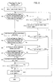
- FIG. 2 is a flow chart showing the process of manual feeding operation in this embodiment.
- a step feed or a jog feed is selected and performed depending on the time for which the on-state of an axis motion key has continued.
- the value of a parameter giving an on-state duration on the basis of which switching from the step feed to the jog feed is made is entered, for example using the keyboard 14 and stored in the nonvolatile RAM of the memory 12 in advance.
- the values of parameters giving on-state durations on the basis of which the jog feed is switched from a low speed to a medium speed, and from the medium speed to a high speed are set and stored in the memory.
- the motion amount for the step feed and the speeds for a low-speed jog feed, a medium-speed jog feed and a high-speed jog feed are also set in advance.
- the processor 11 When one of the axis motion keys Kx + , Kx - , Ky + , Ky - , Kz + , Kz - , Ku + , Ku - , Kv + and Kv - on the control panel 20 is pressed, namely placed in on-state, the processor 11 starts the process shown in FIG. 2. First, the processor 11 resets and starts a timer T for measuring the time for which the on-state of an axis motion key has continued (Step S1). Then the processor 11 reads the time measured by the timer T, and determines whether or not it has reached the predetermined length of time on the basis of which switching from the step feed to the jog feed is made (Step S2).
- Step S12 If not, whether the axis motion key pressed is now in off-state or not is determined (Step S12). Steps S2 and S12 are repeated this way.
- the servomotor for driving the axis corresponding to the axis motion key operated is driven in the direction corresponding to the axis motion key operated, by the predetermined amount, and the measurement of time by the timer T is stopped (Step S13).
- the time for which the axis motion key Kx + was pressed does not reach the length of time predetermined for switching to the jog feed.
- the servomotor 22x for driving the X axis is driven in the positive direction by the predetermined amount to move the table in the X-axis direction.
- Step S3 When an operator presses an axis motion key for a long time and the time measured by the timer T exceeds the length of time predetermined for switching to the jog feed, the servomotor for the axis corresponding to the axis motion key pressed is driven in the direction corresponding to the axis motion key pressed (positive or negative direction) at the predetermined low speed (Step S3). Then, it is determined whether or not the time measured by the timer T has reached the length of time predetermined for switching to the medium-speed jog feed (Step S4). If not, whether the axis motion key pressed is now in off-state or not is determined (Step S5). If it is still in on-state, Step S3 is taken again.
- Steps S3, S4 and S5 are repeated this way. During the repetition of Steps S3, S4 and S5, if it is found in Step S5 that the axis motion key pressed is now in off-state, the jog feed is stopped by stopping the driving of the servomotor, and the measurement of time by the timer T is also stopped (Step S11).
- Step S4 when it is found in Step S4 that the time measured by the timer T has reached the length of time predetermined for switching to the medium-speed jog feed, the jog feed is switched to the medium speed by driving the servomotor for the feed axis at the predetermined medium speed (Step S6). Then, it is determined whether or not the time measured by the timer T has reached the length of time predetermined for switching to the high-speed jog feed (Step S7). If not, it is determined whether or not the axis motion key pressed is now in off-state (Step S8). If it is still in on-state, Step S6 is taken again. Steps S6, S7 and S8 are repeated this way, during which the feed axis is driven at the predetermined medium speed. During the repetition of Steps S6, S7 and S8, if it is found that the axis motion key pressed is now in off-state (Step S8), Step S11 is taken, namely the timer is stopped and the jog feed is stopped
- Step S9 When the time measured by the timer T has reached the length of time predetermined for switching to the high-speed jog feed, the jog feed is switched to the high speed by driving the servomotor for the axis at the predetermined high speed (Step S9). Then, whether the axis motion key has been tuned off or not is monitored (Step S10), and when it is found that the axis motion key is in off-state, the jog feed and the measurement of time by the timer T are stopped (Step S11).
- the jog feed is selected by pressing a corresponding axis motion key for a long time. While the axis motion key is pressed, the feed axis is driven to move in the direction corresponding to the axis motion key pressed. Further, when the axis motion key continues to be pressed longer, the feeding speed is increased stepwise. This means that the speed at which the feed axis is jog-fed can be selected by adjusting the time for which the axis motion key is pressed.
- a feed axis should be exactly placed in an intended position after roughly placed, a corresponding axis motion key is pressed for a moment (for a time shorter than the length of time predetermined for switching to the jog feed).
- the step feed is performed, namely the feed axis is driven by the predetermined amount, so that it is placed exactly in the intended position.
- the embodiment described above is arranged so that the jog feed is switched between three levels of speed, namely the low, medium and high speeds, depending on the time for which an axis motion key has continued to be pressed.
- the jog feed speed may be constant.
- more than three levels of jog feed speed may be provided such that the jog feed can be switched between four or five levels of speed, depending on the time for which an axis motion key has continued to be pressed.
Landscapes
- Engineering & Computer Science (AREA)
- Mechanical Engineering (AREA)
- Chemical & Material Sciences (AREA)
- Chemical Kinetics & Catalysis (AREA)
- Electrochemistry (AREA)
- Physics & Mathematics (AREA)
- Thermal Sciences (AREA)
- Electrical Discharge Machining, Electrochemical Machining, And Combined Machining (AREA)
- Numerical Control (AREA)
Applications Claiming Priority (2)
| Application Number | Priority Date | Filing Date | Title |
|---|---|---|---|
| JP2003398893A JP2005153128A (ja) | 2003-11-28 | 2003-11-28 | ワイヤ放電加工機における手動送り装置 |
| JP2003398893 | 2003-11-28 |
Publications (1)
| Publication Number | Publication Date |
|---|---|
| EP1535684A2 true EP1535684A2 (de) | 2005-06-01 |
Family
ID=34463870
Family Applications (1)
| Application Number | Title | Priority Date | Filing Date |
|---|---|---|---|
| EP04257312A Withdrawn EP1535684A2 (de) | 2003-11-28 | 2004-11-25 | Handbetätigte Steuervorrichtung für eine Drahtfunkenschneidmaschine |
Country Status (4)
| Country | Link |
|---|---|
| US (1) | US7002093B2 (de) |
| EP (1) | EP1535684A2 (de) |
| JP (1) | JP2005153128A (de) |
| CN (1) | CN1621187A (de) |
Cited By (1)
| Publication number | Priority date | Publication date | Assignee | Title |
|---|---|---|---|---|
| CN102019472A (zh) * | 2010-09-30 | 2011-04-20 | 广州市技师学院 | 一种基于快走丝线机床的中走丝线切割方法 |
Families Citing this family (11)
| Publication number | Priority date | Publication date | Assignee | Title |
|---|---|---|---|---|
| ATE517705T1 (de) * | 2007-06-30 | 2011-08-15 | Trumpf Werkzeugmaschinen Gmbh | Werkzeugmaschine und verfahren zum ausschleusen eines werkstückteils |
| CN101342601B (zh) * | 2007-07-13 | 2010-05-19 | 天水星火机床有限责任公司 | 多种操纵方式的数普兼容机床 |
| CN101875141B (zh) * | 2010-03-08 | 2012-01-11 | 苏州新火花机床有限公司 | 一种中走丝机床多状态实时采样数字伺服进给系统 |
| JP5199425B2 (ja) * | 2011-08-17 | 2013-05-15 | ファナック株式会社 | 自動的に加工方向を切換え可能な手動加工機能を備えた数値制御装置 |
| JP5872848B2 (ja) * | 2011-10-28 | 2016-03-01 | ファナック株式会社 | 手動送り速度を変更可能な数値制御装置 |
| JP5199447B1 (ja) * | 2011-12-09 | 2013-05-15 | ファナック株式会社 | 回転軸を備えたワイヤ放電加工機 |
| JP5850894B2 (ja) * | 2013-09-09 | 2016-02-03 | ファナック株式会社 | テーパ加工を行うワイヤ放電加工機を制御する数値制御装置 |
| JP5800878B2 (ja) | 2013-10-30 | 2015-10-28 | ファナック株式会社 | 放電加工機 |
| JP6542724B2 (ja) * | 2016-07-26 | 2019-07-10 | ファナック株式会社 | 数値制御装置 |
| JP6795560B2 (ja) * | 2018-08-22 | 2020-12-02 | ファナック株式会社 | 制御装置および軸送り制御方法 |
| JP6795559B2 (ja) * | 2018-08-22 | 2020-12-02 | ファナック株式会社 | 制御装置および軸送り制御方法 |
Family Cites Families (5)
| Publication number | Priority date | Publication date | Assignee | Title |
|---|---|---|---|---|
| JPS5976718A (ja) * | 1982-10-25 | 1984-05-01 | Fanuc Ltd | ワイヤカツト放電加工条件設定方式 |
| JPH0217506A (ja) | 1988-07-06 | 1990-01-22 | Fanuc Ltd | 数値制御装置 |
| JP3014562B2 (ja) * | 1993-05-07 | 2000-02-28 | ファナック株式会社 | 放電加工装置及び放電加工装置の加工条件設定方法 |
| JP3274272B2 (ja) * | 1994-03-08 | 2002-04-15 | ファナック株式会社 | 座標系の手動送り方法並びにロボット制御装置 |
| DE19882992T1 (de) * | 1998-05-12 | 2001-09-27 | Mitsubishi Electric Corp | Numerisch steuernde Einrichtung für ein Bearbeitungswerkzeug |
-
2003
- 2003-11-28 JP JP2003398893A patent/JP2005153128A/ja active Pending
-
2004
- 2004-11-23 US US10/994,255 patent/US7002093B2/en not_active Expired - Fee Related
- 2004-11-25 EP EP04257312A patent/EP1535684A2/de not_active Withdrawn
- 2004-11-26 CN CNA2004100962987A patent/CN1621187A/zh active Pending
Non-Patent Citations (4)
| Title |
|---|
| "B2 Function of the system", AGIECUT 100,200,300, June 1986 (1986-06-01), pages 5,14 - 15, XP002991478 |
| "EINFACHES UND SCHENELLES EINRICHTEN", AGIECUT DEM 425+740 CNC SCHNEIDERODIERANLAGEN MIT AGIECONIC 3, May 1982 (1982-05-01), pages 1 - 4, XP002991479 |
| "Flexibility of control movements with AGIECUT Handbox", AGIE, vol. 1138, February 1983 (1983-02-01), XP002991476 |
| "Handling-Optimum aus einfachheit & Sicherheit", AGIE BROCHURE DAS OPTIMUM KOMPLEXER SCHNEIDEROSION AGIECUT 100-200-300, June 1986 (1986-06-01), pages 10 - 11, XP002991477 |
Cited By (1)
| Publication number | Priority date | Publication date | Assignee | Title |
|---|---|---|---|---|
| CN102019472A (zh) * | 2010-09-30 | 2011-04-20 | 广州市技师学院 | 一种基于快走丝线机床的中走丝线切割方法 |
Also Published As
| Publication number | Publication date |
|---|---|
| JP2005153128A (ja) | 2005-06-16 |
| US20050115928A1 (en) | 2005-06-02 |
| CN1621187A (zh) | 2005-06-01 |
| US7002093B2 (en) | 2006-02-21 |
Similar Documents
| Publication | Publication Date | Title |
|---|---|---|
| US7002093B2 (en) | Manual feed device in wire electric discharge machine | |
| KR900001932B1 (ko) | 사출 성형기의 계량 혼련 방법 | |
| KR970002297B1 (ko) | 전동식 사출성형기의 배압제어방법 및 그의 장치 | |
| US4689457A (en) | Wire-cut electric discharge machine | |
| KR920007640B1 (ko) | 와이어 방전가공장치 | |
| EP0649697B1 (de) | Vorrichtung zum elektroerosiven bearbeiten und maschinenzustandseinstellverfahren | |
| JPH0691435A (ja) | 放電加工機及び放電加工方法 | |
| JPH068054A (ja) | ワイヤカット放電加工機の放電加工モニタ方法 | |
| JPH03121722A (ja) | ワイヤカット放電加工機の加工条件設定方法 | |
| EP0233292A1 (de) | Regelungssystem für eine von servomotoren angetriebene einspritzgiessvorrichtung | |
| EP0649698A1 (de) | Vorrichtung zum elektroerosiven bearbeiten | |
| JP2688128B2 (ja) | 放電加工装置 | |
| JPH06277949A (ja) | ワイヤカット放電加工装置 | |
| JPH05220626A (ja) | ワイヤ放電加工機の加工制御装置 | |
| JP2885228B2 (ja) | ワイヤ放電加工方法及び装置 | |
| JP3032336B2 (ja) | 放電加工方法 | |
| EP0706848A1 (de) | Drahtschneidefunkenerosionsmaschine und bearbeitungsverfahren hierfür | |
| JP2591413B2 (ja) | ローダ制御装置 | |
| JP3036337B2 (ja) | ワイヤ放電加工機 | |
| JP2750394B2 (ja) | ワイヤカット放電加工機の表示方法 | |
| JPH05220625A (ja) | ワイヤカット放電加工機の加工条件設定方式 | |
| JP2640693B2 (ja) | 射出成形機の手動スクリュー制御方法 | |
| JP3097276B2 (ja) | 放電加工機 | |
| JPH0386428A (ja) | ワイヤカット放電加工機の断線修復方法 | |
| JPS5976719A (ja) | ワイヤカツト放電加工条件切換方式 |
Legal Events
| Date | Code | Title | Description |
|---|---|---|---|
| PUAI | Public reference made under article 153(3) epc to a published international application that has entered the european phase |
Free format text: ORIGINAL CODE: 0009012 |
|
| AK | Designated contracting states |
Kind code of ref document: A2 Designated state(s): AT BE BG CH CY CZ DE DK EE ES FI FR GB GR HU IE IS IT LI LU MC NL PL PT RO SE SI SK TR |
|
| AX | Request for extension of the european patent |
Extension state: AL HR LT LV MK YU |
|
| TPAC | Observations filed by third parties |
Free format text: ORIGINAL CODE: EPIDOSNTIPA |
|
| STAA | Information on the status of an ep patent application or granted ep patent |
Free format text: STATUS: THE APPLICATION HAS BEEN WITHDRAWN |
|
| 18W | Application withdrawn |
Effective date: 20060530 |