EP1535678B2 - Zusammenbau von Kupferplattenkassetten - Google Patents
Zusammenbau von Kupferplattenkassetten Download PDFInfo
- Publication number
- EP1535678B2 EP1535678B2 EP04025282A EP04025282A EP1535678B2 EP 1535678 B2 EP1535678 B2 EP 1535678B2 EP 04025282 A EP04025282 A EP 04025282A EP 04025282 A EP04025282 A EP 04025282A EP 1535678 B2 EP1535678 B2 EP 1535678B2
- Authority
- EP
- European Patent Office
- Prior art keywords
- copper plate
- water tank
- projections
- copper
- plate cartridge
- Prior art date
- Legal status (The legal status is an assumption and is not a legal conclusion. Google has not performed a legal analysis and makes no representation as to the accuracy of the status listed.)
- Expired - Lifetime
Links
Images
Classifications
-
- B—PERFORMING OPERATIONS; TRANSPORTING
- B22—CASTING; POWDER METALLURGY
- B22D—CASTING OF METALS; CASTING OF OTHER SUBSTANCES BY THE SAME PROCESSES OR DEVICES
- B22D11/00—Continuous casting of metals, i.e. casting in indefinite lengths
- B22D11/04—Continuous casting of metals, i.e. casting in indefinite lengths into open-ended moulds
- B22D11/055—Cooling the moulds
Definitions
- the invention relates to a copper plate cassette for billet continuous casting, consisting of four interconnected to form a rectangular tube copper plates, which are each bolted to a water tank.
- the document DE 198 42 674 A1 describes a mold wall of a continuous casting mold, which consists of a Kokilleninnenplatte and connected to this via screw connections water tank, the Kokilleninnenplatte on its side facing the water box side webs with intervening grooves having a groove width, in which patches are arranged.
- the grooves have undercuts with an undercut thickness, that the filling pieces have connecting elements with a connecting element thickness, that the filling pieces releasably engage in the undercuts, and that the screw connections are arranged between the filling pieces and the water box.
- the document DE 198 26 522 A1 describes a mold wall of a continuous casting mold, which consists of a Kokilleninnenplatte and connected to this via screw connections water tank, the Kokilleninnenplatte on its side facing the plenum side webs with grooves extending therebetween, are arranged in a filling.
- the filler pieces have at least one expansion element for frictional connection with the inner mold plate.
- the screw connections are arranged between the filling pieces and the water box.
- the document EP 1 025 929 A1 discloses an arrangement for positive and non-positive connection of a cooling channels having mold plate with a water tank by means of expansion screws.
- C-shaped mounting rails are fastened on the one hand with one of its webs on the mold plate and on the other hand C-shaped support rails connected to one of their webs via an adapter plate with the water box.
- the other webs of the connecting rails or the support rails are in such a form-fitting manner to each other that transverse and longitudinal movements of the mold plate takes place as a result of thermal expansion predominantly to exclusively between the webs of the mounting rails.
- the document WO 97 43063 discloses a liquid-cooled mold for continuously casting thin steel plates with two sidewalls opposite each other, a copper plate and a steel backing plate.
- the copper plates defining the mold cavity are detachably connected to the support plates by metal bolts, which are made of CuNiMnFe alloy.
- the metal bolts are welded to the copper plates using a nickel ring as a filler filler.
- Channels for coolant are arranged in the copper plates and cooling holes in the region of the cross-sectional plane above the metal bolts.
- the document DE 100 39 625 A1 relates to a liquid-cooled plate mold for continuous casting of metals, in particular of steel materials comprising highly heat conductive Kokillenplatten of copper or copper alloys, which are connected by means of fastening bolts each with a water tank or with a support plate. Threaded moldings are arranged on the water side of each mold plate, which are connected by soldered joints or by electron beam welding with the mold plates frictionally as mounting pieces.
- the present invention seeks to provide a new and much simplified design of the copper plate cassette, which accounts in particular the laborious processing steps in the production of T-slots in the copper plates.
- the procurement of the plates is considerably cheaper.
- each water tank overlaps with lateral projections in lateral cutouts of the toasting water box and slots are penetrated in the projections of clamping screws in the end-side threaded holes of the respective channel box under training of surface pressures are screwed.
- the production is essentially limited to the production of threaded holes in the water boxes and as fasteners standardized expansion screws can be used. Manufacturing, assembly and storage are considerably cheaper and easier. Also, the production of T-nuts can be omitted, because thus the screwing takes place directly on the water tanks.
- the threaded holes are provided on the water tank each between two projections in a central arrangement.
- An expedient further embodiment of the invention provides that the width of the slots in the projections is greater than the shaft diameter of the clamping screws.
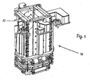
- the copper plate cassette 12 for billet continuous casting according to FIG. 1 consists of four mutually braced copper plates 1, which are each bolted to a water tank 4.
- Each copper plate 1 is connected via the water boxes 4 to a corner joint 5.
- Each water box engages with lateral projections 8 in the lateral cutouts of the tapping water box. 4
- the lateral projections 8 of the water boxes 4 contain slots 9, which are penetrated by clamping screws 10, which are screwed into the frontal threaded holes 11 of the respective ticking water box 4 to form surface pressure for sealing the copper plates 1.
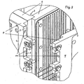
- FIG. 3 shows that bores 11 are each provided between two projections 8, 8 'in a central arrangement.
- the stress on tension screws 10 are high-strength expansion screws.
- the width of the slots 9 in the projections 8 is greater than the shank diameter of the clamping screws 10.
- Each copper plate 1 is the back, ie provided on the water box 4 facing cold plate side with recessed in the plate cooling slots through which the coolant flows water.
Landscapes
- Engineering & Computer Science (AREA)
- Mechanical Engineering (AREA)
- Continuous Casting (AREA)
- Particle Accelerators (AREA)
- Packaging Of Annular Or Rod-Shaped Articles, Wearing Apparel, Cassettes, Or The Like (AREA)
Description
- Die Erfindung betrifft eine Kupferplattenkassette für Vorblock-Stranggießanlagen, bestehend aus vier unter Ausbildung eines rechteckigen Rohres miteinander verbundenen Kupferplatten, die jeweils an einem Wasserkasten angeschraubt sind.
- Kupferplattenkassetten für Vorblock-Stranggießanlagen weisen üblicherweise je vier miteinander verschraubte Kupferplatten auf, die jeweils mit einem Wasserkasten verbunden sind. Dabei werden vier Einheiten aus Kupferplatte und Wasserkasten derart miteinander zusammengefügt, dass sich ein rechteckiges Rohr ergibt. Beim Stand der Technik sind hierfür einige Ausführungsformen bekannt:
- Beispielsweise sind an die Kupferplatten seitlich T-Nuten angearbeitet, die T-Nutsteine mit Innengewinde aufnehmen, wobei Schrauben jeweils kreuzweise die Wasserkästen mit den senkrecht dazu stehenden Kupferplatten verbinden.
- Diese Bauart ergibt einen erheblichen Bearbeitungsaufwand an den Kupferplatten.
- Das Dokument
DE 198 42 674 A1 beschreibt eine Kokillenwand einer Stranggießkokille, die aus einer Kokilleninnenplatte und einem mit dieser über Schraubverbindungen verbundenen Wasserkasten besteht, wobei die Kokilleninnenplatte auf ihrer dem Wasserkasten zugewandten Seite Stege mit dazwischen verlaufenden Nuten mit einer Nutbreite aufweist, in denen Füllstücke angeordnet sind. Um die Kokilleninnenplatte am Wasserkasten zu befestigen ist vorgesehen, dass die Nuten Hinterschneidungen mit einer Hinterschneidungsdicke aufweisen, dass die Füllstücke Verbindungselemente mit einer Verbindungselementdicke aufweisen, dass die Füllstücke lösbar in die Hinterschneidungen eingreifen, und dass die Schraubverbindungen zwischen den Füllstücken und dem Wasserkasten angeordnet sind. - Das Dokument
DE 198 26 522 A1 beschreibt eine Kokillenwand einer Stranggießkokille, die aus einer Kokilleninnenplatte und einem mit dieser über Schraubverbindungen verbundenen Wasserkasten besteht, wobei die Kokilleninnenplatte auf ihrer dem Wasserkasten zugewandten Seite Stege mit dazwischen verlaufenden Nuten aufweist, in einen Füllstücke angeordnet sind. Die Füllstücke weisen mindestens ein Spreizelement zur reibschlüssigen Verbindung mit der Kokilleninnenplatte auf. Die Schraubverbindungen sind zwischen den Füllstücken und dem Wasserkasten angeordnet. - Das Dokument
EP 1 025 929 A1 offenbart eine Anordnung zum form- und kraftschlüssigen Verbinden einer Kühlkanäle aufweisenden Kokillenplatte mit einem Wasserkasten mittels Dehnschrauben.
Bei dieser Anordnung sind C-förmige Befestigungsschienen einerseits mit einem ihrer Stege an der Kokillenplatte befestigt und andererseits C-förmige Halteschienen mit einem ihrer Stege über eine Adapterplatte mit dem Wasserkasten verbindbar. Die anderen Stege der Verbindungsschienen bzw. der Halteschienen liegen derart formschlüssig aneinander, dass Quer- und Längsbewegungen der Kokillenplatte in Folge thermischer Dehnung überwiegend bis ausschließlich zwischen den Stegen der Befestigungsschienen erfolgt. - Das Dokument
WO 97 43063
Die Metallbolzen sind an die Kupferplatten angeschweißt unter Verwendung eines Nickelringes als Schweißmaterialfüller. Kanäle für Kühlmittel sind in den Kupferplatten und Kühlbohrungen im Bereich der Querschnittsebene oberhalb der Metallbolzen angeordnet. - Das Dokument
DE 100 39 625 A1 betrifft eine flüssigkeitsgekühlte Plattenkokille zum Stranggießen von Metallen, insbesondere von Stahlwerkstoffen, umfassend hochwärmeleitfähige Kokillenplatten aus Kupfer oder Kupferlegierungen, die mittels Befestigungsbolzen jeweils mit einem Wasserkasten bzw. mit einer Stützplatte verbunden sind.
Auf der Wasserseite jeder Kokillenplatte sind mit Gewinde ausgebildete Formteile angeordnet, die durch Lötverbindungen oder durch Elektronenstrahlschweißung mit den Kokillenplatten kraftschlüssig als Befestigungsstücke verbunden sind. - Ausgehend vom vorgenannten Stand der Technik liegt der Erfindung die Aufgabe zugrunde, eine neue und wesentlich vereinfachte Bauart der Kupferplattenkassette anzugeben, bei der insbesondere die arbeitsaufwendigen Bearbeitungsschritte bei der Herstellung der T-Nuten in den Kupferplatten entfallen. Damit wird die Beschaffung der Platten erheblich günstiger.
- Zur Lösung der Aufgabe wird bei einer Kupferplattenkassette der im Oberbegriff von Anspruch 1 genannten Art vorgeschlagen, dass jeder Wasserkasten mit seitlichen Vorsprüngen in seitliche Ausfräsungen des aneckenden Wasserkastens übergreift und Schlitze in den Vorsprüngen von Spannschrauben durchdrungen sind, die in stirnseitige Gewindebohrungen des jeweiligen Wasserkastens unter Ausbildung von Flächenpressungen einschraubbar sind.
- Mit großem Vorteil beschränkt sich die Fertigung im Wesentlichen auf die Herstellung von Gewindebohrungen in den Wasserkästen und als Verbindungselemente können genormte Dehnschrauben verwendet werden. Fertigung, Montage sowie Lagerhaltung werden erheblich günstiger und einfacher. Auch kann die Fertigung der T-Nutensteine entfallen, weil damit die Verschraubung direkt an den Wasserkästen erfolgt.
- In Ausgestaltung der Erfindung wird vorgeschlagen, dass die Gewindebohrungen am Wasserkasten jeweils zwischen zwei Vorsprüngen in mittiger Anordnung vorgesehen sind.
- Eine zweckmäßige weitere Ausgestaltung der Erfindung sieht vor, dass die Breite der Schlitze in den Vorsprüngen größer als der Schaftdurchmesser der Spannschrauben ausgebildet ist.
- Weitere Vorteile und Einzelheiten der Erfindung ergeben sich aus der nachfolgenden Beschreibung eines Ausführungsbeispiels in Verbindung mit den Zeichnungen. Dabei zeigen in Prinzipdarstellung:
- Figur 1
- eine Kokille mit Kupferplattenkassetten in perspektivischer Ansicht in Form eines rechteckigen Rohres,
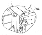
- Figur 2
- in perspektivischer Ansicht,gemäß der Ausschnittvergrößerung A in
Figur 1 , Eckverbindungen zwischen Stirnseiten einer Kokillenplatte und eines Wasserkastens, - Figur 3
- Die Verbindung von Wasserkästen mit seitlichen Vorsprüngen durch Spannschrauben in Gewindebohrungen.
- Die Kupferplattenkassette 12 für Vorblock-Stranggießanlagen gemäß
Figur 1 besteht aus vier miteinander verspannten Kupferplatten 1, wobei diese jeweils auf einen Wasserkasten 4 geschraubt sind. - Gemäß
Figur 2 ist jede Kupferplatte 1 über die Wasserkästen 4 zu einer Eckverbindung 5 zusammenfügbar. - Jeder Wasserkasten greift mit seitlichen Vorsprüngen 8 in die seitlichen Ausfräsungen des aneckenden Wasserkastens 4.
- Die seitlichen Vorsprünge 8 der Wasserkästen 4 enthalten Schlitze 9, die von Spannschrauben 10 durchdrungen sind, die in die stirnseitigen Gewindebohrungen 11 des jeweils aneckenden Wasserkastens 4 unter Ausbildung von Flächenpressung zur Abdichtung der Kupferplatten 1 einschraubbar sind.
-
Figur 3 zeigt, dass Bohrungen 11 jeweils zwischen zwei Vorsprüngen 8, 8' in mittiger Anordnung vorgesehen sind. Die auf Zug beanspruchten Spannschrauben 10 sind hochfeste Dehnschrauben. Die Breite der Schlitze 9 in den Vorsprüngen 8 ist größer als der Schaftdurchmesser der Spannschrauben 10. Jede Kupferplatte 1 ist rückseitig, d. h. auf der dem Wasserkasten 4 zugewandten kalten Plattenseite mit in der Platte eingelassenen Kühlschlitzen versehen, durch die das Kühlmittel Wasser strömt.
Claims (4)
- Kupferplattenkassette (12) für Vorblock-Stranggießanlagen, bestehend aus vier unter Ausbildung eines rechteckigen Rohres miteinander verbundenen Kupferplatten (1), die jeweils an einem Wasserkasten (4) angeschraubt sind, wobei jede den Wasserkasten (4) aufnehmende Kupferplatte (1) zu einer Eckverbindung (5) zusammenfügbar ist,
dadurch gekennzeichnet,
dass jeder Wasserkasten (4) mit seitlichen Vorsprüngen (8) in seitliche Ausfräsungen (7) des aneckenden Wasserkastens übergreift und Schlitze (9) in den Vorsprüngen (8) von Spannschrauben (10) durchdrungen sind, die in stirnseitige Gewindebohrungen (11) des jeweiligen Wasserkastens (4) unter Ausbildung von Flächenpressungen einschraubbar sind. - Kupferplattenkassette nach Anspruch 1,
dadurch gekennzeichnet,
dass die Gewindebohrungen (11) am Wasserkasten (4) jeweils zwischen zwei Vorsprüngen (8, 8') in mittiger Anordnung vorgesehen sind. - Kupferplattenkassette nach Anspruch 1 oder 2,
dadurch gekennzeichnet,
dass die auf Zug beanspruchbaren Spannschrauben (10) hochfeste Dehnschrauben sind. - Kupferplattenkassette nach Anspruch 1 oder 2,
dadurch gekennzeichnet,
dass die Breite der Schlitze (9) in den Vorsprüngen (8) größer als der Schaftdurchmesser der Spannschrauben (10) ausgebildet ist.
Applications Claiming Priority (2)
| Application Number | Priority Date | Filing Date | Title |
|---|---|---|---|
| DE10356318A DE10356318A1 (de) | 2003-11-28 | 2003-11-28 | Zusammenbau von Kupferplattenkassetten |
| DE10356318 | 2003-11-28 |
Publications (3)
| Publication Number | Publication Date |
|---|---|
| EP1535678A1 EP1535678A1 (de) | 2005-06-01 |
| EP1535678B1 EP1535678B1 (de) | 2008-03-19 |
| EP1535678B2 true EP1535678B2 (de) | 2011-06-22 |
Family
ID=34442402
Family Applications (1)
| Application Number | Title | Priority Date | Filing Date |
|---|---|---|---|
| EP04025282A Expired - Lifetime EP1535678B2 (de) | 2003-11-28 | 2004-10-25 | Zusammenbau von Kupferplattenkassetten |
Country Status (3)
| Country | Link |
|---|---|
| EP (1) | EP1535678B2 (de) |
| AT (1) | ATE389482T1 (de) |
| DE (2) | DE10356318A1 (de) |
Citations (2)
| Publication number | Priority date | Publication date | Assignee | Title |
|---|---|---|---|---|
| JPS59150644A (ja) † | 1983-02-16 | 1984-08-28 | Mitsubishi Heavy Ind Ltd | 連続鋳造用モ−ルド |
| FR2584322A1 (fr) † | 1985-07-04 | 1987-01-09 | Fives Cail Babcock | Dispositif d'assemblage des cotes d'une lingotiere de coulee continue |
Family Cites Families (2)
| Publication number | Priority date | Publication date | Assignee | Title |
|---|---|---|---|---|
| DE19904149A1 (de) * | 1999-02-03 | 2000-08-10 | Sms Demag Ag | Anordnung zum Verbinden einer Kokillenplatte mit einem Wasserkasten |
| DE10051489A1 (de) * | 2000-10-17 | 2002-04-18 | Sms Demag Ag | Plattenkokille zum Stranggießen von Metall, insbesondere von Stahl |
-
2003
- 2003-11-28 DE DE10356318A patent/DE10356318A1/de not_active Withdrawn
-
2004
- 2004-10-25 AT AT04025282T patent/ATE389482T1/de active
- 2004-10-25 EP EP04025282A patent/EP1535678B2/de not_active Expired - Lifetime
- 2004-10-25 DE DE502004006561T patent/DE502004006561D1/de not_active Expired - Lifetime
Patent Citations (2)
| Publication number | Priority date | Publication date | Assignee | Title |
|---|---|---|---|---|
| JPS59150644A (ja) † | 1983-02-16 | 1984-08-28 | Mitsubishi Heavy Ind Ltd | 連続鋳造用モ−ルド |
| FR2584322A1 (fr) † | 1985-07-04 | 1987-01-09 | Fives Cail Babcock | Dispositif d'assemblage des cotes d'une lingotiere de coulee continue |
Non-Patent Citations (10)
| Title |
|---|
| Abnahmeprotokoll der Teilanlage 2.3.3 vom 20.09.2000 † |
| Auszug aus dem Kaufvertrag vom 2.7.1998 zwischen der Voest-Alpine Industrieanlagenbau GmbH und der Voest-Alpine Stahl Donawitz GmbH † |
| BRANDL W. ET AL: "Donawitz Compact - The Process Route to Europe's No. 1 Rail Producer"", June 2000, IN PROCEEDINGS DER C2000, PAPER NO. 31, LINZ † |
| Eidesstattliche Erklärung vom 30.9.2008 † |
| Konferenzprogramm der Continuous Casting Conference (CCC) 2000, Linz, Juni 2000 † |
| LEINGRUBER F. ET AL: "High-Performance Machine Head - A Success Story"", June 2000, IN PROCEEDINGS DER CCC 2000, PAPER NO. 34, LINZ † |
| Technische Anlagenspezifikation "Stranggiessanlage (Stako /Mechanische Ausführung)", 6 Seiten † |
| Teilnehmerliste der CCC 2000, Linz, Juni 2000 † |
| Umschlagseite und Inhaltsverzeichnis der Proceedings der CCC 2000, Linz, Juni 2000 † |
| Zeichnungen VKD.CV.2512-M1000/ZSZ001 "Kokille/Mould", 2 Seiten † |
Also Published As
| Publication number | Publication date |
|---|---|
| EP1535678B1 (de) | 2008-03-19 |
| DE502004006561D1 (de) | 2008-04-30 |
| ATE389482T1 (de) | 2008-04-15 |
| EP1535678A1 (de) | 2005-06-01 |
| DE10356318A1 (de) | 2005-06-23 |
Similar Documents
| Publication | Publication Date | Title |
|---|---|---|
| EP1468760B1 (de) | Rohrkokille zum Stranggiessen | |
| EP1398099B1 (de) | Flüssigkeitsgekühlte Kokille zum Stranggiessen von Metallen | |
| EP0912271B1 (de) | Flüssigkeitsgekühlte kokille | |
| EP3487650B1 (de) | Kokillenplatte und kokille | |
| EP1555073B1 (de) | Flüssigkeitsgekühlte Stranggiesskokille | |
| EP1138417A1 (de) | Flüssigkeitsgekühle Plattenkokille | |
| DE2858250C2 (de) | Stranggießkokille | |
| EP1535678B2 (de) | Zusammenbau von Kupferplattenkassetten | |
| EP2431112A1 (de) | Druckgusskolben | |
| DE69127853T2 (de) | Kokillen-Vorrichtung mit veränderlicher Breite | |
| DE102007001931A1 (de) | Kokillenwand | |
| WO2002007915A1 (de) | Stranggiesskokille mit den giessquerschnitt umschliessenden kupferplatten | |
| EP1378940A2 (de) | Kühlvorrichtung für Halbleiterbauelemente oder dergleichen Einrichtungen | |
| DE202021102497U1 (de) | Kokillenplatte, Gewindeeinsatz und Kokillenplattenanordnung | |
| EP1025929A1 (de) | Anordnung zum Verbinden einer Kokillenplatte mit einem Wasserkasten | |
| DE102020005960A1 (de) | Platte mit mindestens einer Nut in ihrer Oberfläche, Verfahren zur Herstellung einer Nut in der Oberfläche einer Platte und Nutenstein | |
| DE19716450A1 (de) | Flüssigkeitsgekühlte Kokille | |
| DE19741130C1 (de) | Lösbare Stoßverbindung für Rohre | |
| DE102008023667B4 (de) | Werkzeug zum Umformen eines Werkstückes, insbesondere Schmiedewerkzeug | |
| DE2724885C2 (de) | Flüssigkeitsgekühlte Gleitkokille, insbesondere für Elektroschlacke-Umschmelzanlagen | |
| DE102015110522B4 (de) | Verfahren zur Herstellung von Rohteilen mit innenliegenden Kanälen | |
| DE102015005092B4 (de) | Formgebendes Werkzeug und Verfahren zu dessen Herstellung | |
| EP1522380B1 (de) | Winkelprofilelement als Ausgangselement zum Aufbau von Vorrichtungen zur Aufnahme von Werkstücken | |
| DE102025109207A1 (de) | Kühlplatte für einen Energiespeicher | |
| DE1978284U (de) | Kuehlkoerper mit kuehlrippen fuer halbleiterbauelemente. |
Legal Events
| Date | Code | Title | Description |
|---|---|---|---|
| PUAI | Public reference made under article 153(3) epc to a published international application that has entered the european phase |
Free format text: ORIGINAL CODE: 0009012 |
|
| 17P | Request for examination filed |
Effective date: 20041103 |
|
| AK | Designated contracting states |
Kind code of ref document: A1 Designated state(s): AT BE BG CH CY CZ DE DK EE ES FI FR GB GR HU IE IT LI LU MC NL PL PT RO SE SI SK TR |
|
| AX | Request for extension of the european patent |
Extension state: AL HR LT LV MK |
|
| AKX | Designation fees paid |
Designated state(s): AT BE BG CH CY CZ DE DK EE ES FI FR GB GR HU IE IT LI LU MC NL PL PT RO SE SI SK TR |
|
| GRAP | Despatch of communication of intention to grant a patent |
Free format text: ORIGINAL CODE: EPIDOSNIGR1 |
|
| GRAS | Grant fee paid |
Free format text: ORIGINAL CODE: EPIDOSNIGR3 |
|
| GRAA | (expected) grant |
Free format text: ORIGINAL CODE: 0009210 |
|
| AK | Designated contracting states |
Kind code of ref document: B1 Designated state(s): AT BE BG CH CY CZ DE DK EE ES FI FR GB GR HU IE IT LI LU MC NL PL PT RO SE SI SK TR |
|
| REG | Reference to a national code |
Ref country code: GB Ref legal event code: FG4D Free format text: NOT ENGLISH |
|
| REG | Reference to a national code |
Ref country code: CH Ref legal event code: EP |
|
| REF | Corresponds to: |
Ref document number: 502004006561 Country of ref document: DE Date of ref document: 20080430 Kind code of ref document: P |
|
| REG | Reference to a national code |
Ref country code: IE Ref legal event code: FG4D Free format text: LANGUAGE OF EP DOCUMENT: GERMAN |
|
| PG25 | Lapsed in a contracting state [announced via postgrant information from national office to epo] |
Ref country code: FI Free format text: LAPSE BECAUSE OF FAILURE TO SUBMIT A TRANSLATION OF THE DESCRIPTION OR TO PAY THE FEE WITHIN THE PRESCRIBED TIME-LIMIT Effective date: 20080319 |
|
| NLV1 | Nl: lapsed or annulled due to failure to fulfill the requirements of art. 29p and 29m of the patents act | ||
| PG25 | Lapsed in a contracting state [announced via postgrant information from national office to epo] |
Ref country code: PL Free format text: LAPSE BECAUSE OF FAILURE TO SUBMIT A TRANSLATION OF THE DESCRIPTION OR TO PAY THE FEE WITHIN THE PRESCRIBED TIME-LIMIT Effective date: 20080319 Ref country code: SI Free format text: LAPSE BECAUSE OF FAILURE TO SUBMIT A TRANSLATION OF THE DESCRIPTION OR TO PAY THE FEE WITHIN THE PRESCRIBED TIME-LIMIT Effective date: 20080319 |
|
| REG | Reference to a national code |
Ref country code: IE Ref legal event code: FD4D |
|
| PG25 | Lapsed in a contracting state [announced via postgrant information from national office to epo] |
Ref country code: CZ Free format text: LAPSE BECAUSE OF FAILURE TO SUBMIT A TRANSLATION OF THE DESCRIPTION OR TO PAY THE FEE WITHIN THE PRESCRIBED TIME-LIMIT Effective date: 20080319 Ref country code: SE Free format text: LAPSE BECAUSE OF FAILURE TO SUBMIT A TRANSLATION OF THE DESCRIPTION OR TO PAY THE FEE WITHIN THE PRESCRIBED TIME-LIMIT Effective date: 20080619 Ref country code: ES Free format text: LAPSE BECAUSE OF FAILURE TO SUBMIT A TRANSLATION OF THE DESCRIPTION OR TO PAY THE FEE WITHIN THE PRESCRIBED TIME-LIMIT Effective date: 20080630 Ref country code: PT Free format text: LAPSE BECAUSE OF FAILURE TO SUBMIT A TRANSLATION OF THE DESCRIPTION OR TO PAY THE FEE WITHIN THE PRESCRIBED TIME-LIMIT Effective date: 20080826 Ref country code: SK Free format text: LAPSE BECAUSE OF FAILURE TO SUBMIT A TRANSLATION OF THE DESCRIPTION OR TO PAY THE FEE WITHIN THE PRESCRIBED TIME-LIMIT Effective date: 20080319 |
|
| PG25 | Lapsed in a contracting state [announced via postgrant information from national office to epo] |
Ref country code: NL Free format text: LAPSE BECAUSE OF FAILURE TO SUBMIT A TRANSLATION OF THE DESCRIPTION OR TO PAY THE FEE WITHIN THE PRESCRIBED TIME-LIMIT Effective date: 20080319 Ref country code: RO Free format text: LAPSE BECAUSE OF FAILURE TO SUBMIT A TRANSLATION OF THE DESCRIPTION OR TO PAY THE FEE WITHIN THE PRESCRIBED TIME-LIMIT Effective date: 20080319 |
|
| PLBI | Opposition filed |
Free format text: ORIGINAL CODE: 0009260 |
|
| EN | Fr: translation not filed | ||
| 26 | Opposition filed |
Opponent name: SIEMENS VAI METALS TECHNOLOGIES GMBH Effective date: 20081218 |
|
| PG25 | Lapsed in a contracting state [announced via postgrant information from national office to epo] |
Ref country code: IE Free format text: LAPSE BECAUSE OF FAILURE TO SUBMIT A TRANSLATION OF THE DESCRIPTION OR TO PAY THE FEE WITHIN THE PRESCRIBED TIME-LIMIT Effective date: 20080319 Ref country code: DK Free format text: LAPSE BECAUSE OF FAILURE TO SUBMIT A TRANSLATION OF THE DESCRIPTION OR TO PAY THE FEE WITHIN THE PRESCRIBED TIME-LIMIT Effective date: 20080319 |
|
| PLAX | Notice of opposition and request to file observation + time limit sent |
Free format text: ORIGINAL CODE: EPIDOSNOBS2 |
|
| BERE | Be: lapsed |
Owner name: SMS DEMAG AG Effective date: 20081031 |
|
| PG25 | Lapsed in a contracting state [announced via postgrant information from national office to epo] |
Ref country code: EE Free format text: LAPSE BECAUSE OF FAILURE TO SUBMIT A TRANSLATION OF THE DESCRIPTION OR TO PAY THE FEE WITHIN THE PRESCRIBED TIME-LIMIT Effective date: 20080319 Ref country code: BG Free format text: LAPSE BECAUSE OF FAILURE TO SUBMIT A TRANSLATION OF THE DESCRIPTION OR TO PAY THE FEE WITHIN THE PRESCRIBED TIME-LIMIT Effective date: 20080619 |
|
| PLBB | Reply of patent proprietor to notice(s) of opposition received |
Free format text: ORIGINAL CODE: EPIDOSNOBS3 |
|
| PG25 | Lapsed in a contracting state [announced via postgrant information from national office to epo] |
Ref country code: MC Free format text: LAPSE BECAUSE OF NON-PAYMENT OF DUE FEES Effective date: 20081031 |
|
| REG | Reference to a national code |
Ref country code: CH Ref legal event code: PL |
|
| RAP2 | Party data changed (patent owner data changed or rights of a patent transferred) |
Owner name: SMS SIEMAG AG |
|
| GBPC | Gb: european patent ceased through non-payment of renewal fee |
Effective date: 20081025 |
|
| PG25 | Lapsed in a contracting state [announced via postgrant information from national office to epo] |
Ref country code: CY Free format text: LAPSE BECAUSE OF FAILURE TO SUBMIT A TRANSLATION OF THE DESCRIPTION OR TO PAY THE FEE WITHIN THE PRESCRIBED TIME-LIMIT Effective date: 20080319 Ref country code: BE Free format text: LAPSE BECAUSE OF NON-PAYMENT OF DUE FEES Effective date: 20081031 |
|
| PG25 | Lapsed in a contracting state [announced via postgrant information from national office to epo] |
Ref country code: LI Free format text: LAPSE BECAUSE OF NON-PAYMENT OF DUE FEES Effective date: 20081031 Ref country code: CH Free format text: LAPSE BECAUSE OF NON-PAYMENT OF DUE FEES Effective date: 20081031 |
|
| PG25 | Lapsed in a contracting state [announced via postgrant information from national office to epo] |
Ref country code: GB Free format text: LAPSE BECAUSE OF NON-PAYMENT OF DUE FEES Effective date: 20081025 |
|
| PG25 | Lapsed in a contracting state [announced via postgrant information from national office to epo] |
Ref country code: LU Free format text: LAPSE BECAUSE OF NON-PAYMENT OF DUE FEES Effective date: 20081025 Ref country code: HU Free format text: LAPSE BECAUSE OF FAILURE TO SUBMIT A TRANSLATION OF THE DESCRIPTION OR TO PAY THE FEE WITHIN THE PRESCRIBED TIME-LIMIT Effective date: 20080920 |
|
| PG25 | Lapsed in a contracting state [announced via postgrant information from national office to epo] |
Ref country code: TR Free format text: LAPSE BECAUSE OF FAILURE TO SUBMIT A TRANSLATION OF THE DESCRIPTION OR TO PAY THE FEE WITHIN THE PRESCRIBED TIME-LIMIT Effective date: 20080319 |
|
| PG25 | Lapsed in a contracting state [announced via postgrant information from national office to epo] |
Ref country code: GR Free format text: LAPSE BECAUSE OF FAILURE TO SUBMIT A TRANSLATION OF THE DESCRIPTION OR TO PAY THE FEE WITHIN THE PRESCRIBED TIME-LIMIT Effective date: 20080620 |
|
| PUAH | Patent maintained in amended form |
Free format text: ORIGINAL CODE: 0009272 |
|
| STAA | Information on the status of an ep patent application or granted ep patent |
Free format text: STATUS: PATENT MAINTAINED AS AMENDED |
|
| 27A | Patent maintained in amended form |
Effective date: 20110622 |
|
| AK | Designated contracting states |
Kind code of ref document: B2 Designated state(s): AT BE BG CH CY CZ DE DK EE ES FI FR GB GR HU IE IT LI LU MC NL PL PT RO SE SI SK TR |
|
| REG | Reference to a national code |
Ref country code: DE Ref legal event code: R102 Ref document number: 502004006561 Country of ref document: DE Effective date: 20110622 |
|
| PG25 | Lapsed in a contracting state [announced via postgrant information from national office to epo] |
Ref country code: FR Free format text: LAPSE BECAUSE OF FAILURE TO SUBMIT A TRANSLATION OF THE DESCRIPTION OR TO PAY THE FEE WITHIN THE PRESCRIBED TIME-LIMIT Effective date: 20090109 |
|
| REG | Reference to a national code |
Ref country code: DE Ref legal event code: R082 Ref document number: 502004006561 Country of ref document: DE Representative=s name: HEMMERICH & KOLLEGEN, DE Ref country code: DE Ref legal event code: R081 Ref document number: 502004006561 Country of ref document: DE Owner name: SMS GROUP GMBH, DE Free format text: FORMER OWNER: SMS SIEMAG AKTIENGESELLSCHAFT, 40237 DUESSELDORF, DE |
|
| P01 | Opt-out of the competence of the unified patent court (upc) registered |
Effective date: 20230707 |
|
| PGFP | Annual fee paid to national office [announced via postgrant information from national office to epo] |
Ref country code: IT Payment date: 20231026 Year of fee payment: 20 Ref country code: DE Payment date: 20231020 Year of fee payment: 20 Ref country code: AT Payment date: 20231020 Year of fee payment: 20 |
|
| REG | Reference to a national code |
Ref country code: DE Ref legal event code: R071 Ref document number: 502004006561 Country of ref document: DE |
|
| REG | Reference to a national code |
Ref country code: AT Ref legal event code: MK07 Ref document number: 389482 Country of ref document: AT Kind code of ref document: T Effective date: 20241025 |