EP1535669A2 - Repandeuse permettant in particulier de déposer des adhésifs et/ou des materiaux polymeres en dispersions dans un liquide - Google Patents
Repandeuse permettant in particulier de déposer des adhésifs et/ou des materiaux polymeres en dispersions dans un liquide Download PDFInfo
- Publication number
- EP1535669A2 EP1535669A2 EP04027743A EP04027743A EP1535669A2 EP 1535669 A2 EP1535669 A2 EP 1535669A2 EP 04027743 A EP04027743 A EP 04027743A EP 04027743 A EP04027743 A EP 04027743A EP 1535669 A2 EP1535669 A2 EP 1535669A2
- Authority
- EP
- European Patent Office
- Prior art keywords
- region
- head
- duct
- spreader according
- passage
- Prior art date
- Legal status (The legal status is an assumption and is not a legal conclusion. Google has not performed a legal analysis and makes no representation as to the accuracy of the status listed.)
- Withdrawn
Links
Images
Classifications
-
- B—PERFORMING OPERATIONS; TRANSPORTING
- B05—SPRAYING OR ATOMISING IN GENERAL; APPLYING FLUENT MATERIALS TO SURFACES, IN GENERAL
- B05C—APPARATUS FOR APPLYING FLUENT MATERIALS TO SURFACES, IN GENERAL
- B05C5/00—Apparatus in which liquid or other fluent material is projected, poured or allowed to flow on to the surface of the work
- B05C5/02—Apparatus in which liquid or other fluent material is projected, poured or allowed to flow on to the surface of the work the liquid or other fluent material being discharged through an outlet orifice by pressure, e.g. from an outlet device in contact or almost in contact, with the work
- B05C5/027—Coating heads with several outlets, e.g. aligned transversally to the moving direction of a web to be coated
-
- B—PERFORMING OPERATIONS; TRANSPORTING
- B05—SPRAYING OR ATOMISING IN GENERAL; APPLYING FLUENT MATERIALS TO SURFACES, IN GENERAL
- B05C—APPARATUS FOR APPLYING FLUENT MATERIALS TO SURFACES, IN GENERAL
- B05C5/00—Apparatus in which liquid or other fluent material is projected, poured or allowed to flow on to the surface of the work
- B05C5/02—Apparatus in which liquid or other fluent material is projected, poured or allowed to flow on to the surface of the work the liquid or other fluent material being discharged through an outlet orifice by pressure, e.g. from an outlet device in contact or almost in contact, with the work
-
- B—PERFORMING OPERATIONS; TRANSPORTING
- B05—SPRAYING OR ATOMISING IN GENERAL; APPLYING FLUENT MATERIALS TO SURFACES, IN GENERAL
- B05C—APPARATUS FOR APPLYING FLUENT MATERIALS TO SURFACES, IN GENERAL
- B05C5/00—Apparatus in which liquid or other fluent material is projected, poured or allowed to flow on to the surface of the work
- B05C5/02—Apparatus in which liquid or other fluent material is projected, poured or allowed to flow on to the surface of the work the liquid or other fluent material being discharged through an outlet orifice by pressure, e.g. from an outlet device in contact or almost in contact, with the work
- B05C5/0254—Coating heads with slot-shaped outlet
-
- B—PERFORMING OPERATIONS; TRANSPORTING
- B05—SPRAYING OR ATOMISING IN GENERAL; APPLYING FLUENT MATERIALS TO SURFACES, IN GENERAL
- B05C—APPARATUS FOR APPLYING FLUENT MATERIALS TO SURFACES, IN GENERAL
- B05C5/00—Apparatus in which liquid or other fluent material is projected, poured or allowed to flow on to the surface of the work
- B05C5/02—Apparatus in which liquid or other fluent material is projected, poured or allowed to flow on to the surface of the work the liquid or other fluent material being discharged through an outlet orifice by pressure, e.g. from an outlet device in contact or almost in contact, with the work
- B05C5/0245—Apparatus in which liquid or other fluent material is projected, poured or allowed to flow on to the surface of the work the liquid or other fluent material being discharged through an outlet orifice by pressure, e.g. from an outlet device in contact or almost in contact, with the work for applying liquid or other fluent material to a moving work of indefinite length, e.g. to a moving web
- B05C5/025—Apparatus in which liquid or other fluent material is projected, poured or allowed to flow on to the surface of the work the liquid or other fluent material being discharged through an outlet orifice by pressure, e.g. from an outlet device in contact or almost in contact, with the work for applying liquid or other fluent material to a moving work of indefinite length, e.g. to a moving web only at particular part of the work
Definitions
- the present invention relates to a spreader particularly for depositing adhesives and/or polymeric materials in liquid dispersion.
- substrates in industrial practice, and their bonding can provide a chosen product or intermediate component; in particular, substrates made of woven material, commonly termed tissues, are widely used to manufacture paper napkins, handkerchiefs, wet wipes, toilet paper, towels, medical wipes, medical drapes and other products.
- adhesives in liquid dispersion of a known type are commonly used; they are interposed between said layers and have mechanical and stability properties that are suitable to meet the requirements of the users of the resulting product.
- Another widespread requirement is to coat one or more of said substrates by means of polymeric materials in a liquid dispersion, in order to obtain particular properties of the product, such as for example a particular fragrance or greater stability of the fibers that compose the substrate.
- One application of this second type of process relates for example to the production of paper handkerchiefs, wet wipes, toilet paper, towels, medical wipes and drapes for medical use.
- Stabilization of the substrate for example by depositing a polymeric material on its surface, is required since especially in the case of substrates that contain mixed fibers said fibers are bonded by means of weak bonds and accordingly tend to separate easily from the surface once they are subjected to an external abrasive action, causing the release of particles that can be inconvenient for the end user.
- the substrates that are used in adhesive bonding processes and in coating processes may be very thin, down to thicknesses on the order of a few microns, so that the products manufactured with them are particularly soft and pleasant to the touch.
- the layers of adhesive or polymeric material deposited for bonding and coating also have an extremely limited thickness, since a deposit that can vary between 0.01 grams per square meter and 20 grams per square meter is required.
- the substrate in the form of a ribbon up to approximately 2700 millimeters wide, must further be processed at a very high speed, advancing at the devices for depositing the liquid solution that contains the adhesive or polymeric materials at a speed that can reach 900 meters per minute.
- recovery of production waste is particularly important and absolutely necessary in order to protect the narrow profit margins; said waste is conveyed and returned to the substrate production cycle by means of appropriate recovery systems.
- the ribbon of substrate is made to slide below a tray that contains the dispersion to be applied and is provided with a slot from which said dispersion can fall onto the substrate, the thickness to be deposited being adjusted by changing the height of said tray with respect to the underlying ribbon.
- a second known type of blade device is constituted by a first rotating roller, on the lateral surface of which the dispersion to be applied is made to adhere; a blade is arranged at right angles to said lateral surface and at an adjustable distance from it, so that downstream of said blade the dispersion that adheres to the first rotating roller has a controlled thickness, which can therefore be transferred to the substrate by means of a second roller that rotates in contact with the first roller.
- the dispersion to be deposited is made to adhere to the lateral surface of a first rotating roller and is transferred from there to a second rotating roller, from which it is finally deposited on the substrate.
- Another drawback is further constituted by the fact that the technologies used in these known types of device entail the formation of large amounts of dirt.
- a second known type of device provides for depositing the liquid dispersion, which contains the bonding or coating materials, by means of spreaders, which are usually used instead to deposit adhesives commonly known as hot-melt.
- These conventional spreading devices are constituted by a deposition head, which generally has a pointed shape and on the end of which there is a slit through which the hot-melt adhesive or, in the case being considered, the liquid dispersion is deposited on the ribbon of substrate that slides in contact with it.
- this dust Since this dust has high hygroscopic properties, it rapidly absorbs part of the liquid component of the dispersion that comprises the adhesive or polymer to be deposited on the substrate, making it impossible to dose correctly or even obstructing the slit provided on the head of the spreader, accordingly forcing frequent and onerous stops of the apparatus.
- known devices constituted by the spreaders described here are used to deposit adhesives of the hot-melt type on substrates, as occurs in various other fields of industrial production.
- adhesives of the hot-melt type are known whose characteristics are compatible with production waste recovery requirements, allowing in principle to use them to bond substrates made of fabric or non-woven fabric.
- a drawback of this known type of adhesive is their cost, which is much higher than the cost of traditional hot-melt adhesives and of adhesives in a liquid dispersion and makes them absolutely unusable to bond two or more substrates made of fabric or non-woven fabric.
- units for depositing adhesive or polymers in a liquid dispersion which are provided with nozzles through which the dispersion that contains the adhesive or polymeric coating material is sprayed against the substrates in the regions where one wishes to obtain deposition of said adhesive or of said polymers.
- the aim of the present invention is to solve the above-mentioned problems, eliminating the drawbacks of the cited background art, by providing a spreader that allows to deposit an adhesive or a polymeric material in a liquid dispersion on one or more substrates constituted by materials made of fabric, non-woven fabric, or a mixture thereof, in a controlled and efficient manner.
- an object of the present invention is to provide a spreader that allows to ensure optimum operation even with substrates that have surface fibers that can separate easily.
- Another object is to provide a spreader that allows to deposit layers of adhesive or of coating material that have a wide variety of shapes and thicknesses.
- Another object is to allow quick and easy transition between the various types of deposition that are available.
- Another object of the invention is to ensure high wear-resistance and to allow quick and easy maintenance, accordingly requiring low operating costs.
- Another object is to provide a spreader that is structurally simple and has low manufacturing costs.
- a spreader particularly for depositing adhesives and/or polymeric materials in a liquid dispersion, characterized in that it comprises a head, which can be associated or is associated with a footing and on which there is an active surface that has a profile constituted by a first convex region, a second flat region, a third concave region and a fourth flat region, a duct being formed within said head and being connected to a tank by means of a first passage and a second passage, a feeder unit being further provided between said tank and said duct.
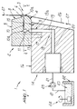
- the reference numeral 1 designates a spreader according to the invention, which is composed of a head 2, which is substantially shaped like a parallelepiped and an active surface 3 of which has a profile that is composed of a first convex region 4, whose profile is constituted for example by an arc of a circle and blends a first wall 5 of the head 2 with a second region 6, which is flat and arranged approximately at right angles to the first wall 5, of the active surface 3.
- the upper end of the second region 6 is blended, by means of a third concave region 7 whose profile is constituted for example by an arc of a circle, with a fourth flat region 8 arranged approximately obliquely.
- the fourth region 8 the upper end of which is contiguous to a second wall 9 of the head 2, is arranged so that said head tapers toward said second wall.
- the active surface 3 of the head 2 is provided with a surface treatment, for example by chrome-plating or other treatments, so that it has excellent wear-resistance characteristics and very low friction coefficients.
- a duct 10 is formed within the head 2 and is arranged for example substantially parallel to the first wall 5; said duct also affects, at a first end 10a, the active surface 3, so that it is open in a point that is located preferably proximate to the blending portion between the first convex region 4 and the second flat region 6.
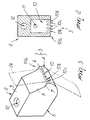
- the duct 10 has a substantially rectangular cross-section, the outline of which is visible on the second region 6.
- profiles 10b which are mutually parallel and equidistant and are arranged longitudinally with respect to the duct, so as to divide the transverse cross-section of said duct, proximate to its first end 10a, into a plurality of passage channels 10c.
- the duct 10 is connected to a first passage 11, which is arranged approximately at right angles to it and is connected, at a first end 11a, to the first wall 5.
- At least one through hole 12 is formed in the head 2 and is suitable to accommodate at least one threaded screw 13, by way of which the head 2 can be coupled to a footing 14 that is adjacent to said head.
- the footing 14 in fact has, in a fifth region 15 of a first surface 16 thereof that is shaped complementarily with respect to the first wall 5 of the head 2 and is for example flat, at least one threaded cavity 17, with a thread that is suitable to mate with the thread provided on the at least one screw 13.
- the head 2 can be associated stably with the footing 14 and it is sufficient to extract the at least one screw 13 in order to disengage said head from said footing.
- a second passage 18 is formed inside the footing 14 and is provided with a first portion 19, which is approximately perpendicular to the fifth region 15 of the first surface 16 and is open, at a first end 19a, onto the fifth region 15, in such a position that when the head 2 is coupled to the footing by means of the at least one screw 13, the first end 19a of the first portion 19 mates with the first end 11a of the first passage 11 provided within the head 2.
- the second passage 18 further comprises a second portion 20, which is for example approximately perpendicular to the first portion 19, is connected to said first portion and, by means of a tube 21, to a tank 22 inside which there is a liquid dispersion 23 that contains in suspension an adhesive or a polymeric coating material.
- a mixing unit 24, shown schematically in Figure 1, is preferably arranged within the tank 22 and is suitable to keep the adhesive or the polymeric coating material suspended in the liquid in which it is dispersed and to render the dispersion 23 homogeneous.
- the spreader 1 further comprises a feeder unit 25, which is constituted by at least one pump, preferably of the gear type, which is shown schematically in the figure and is arranged for example along the tube 21, between the tank 22 and the second portion 20 of the second duct 18.
- a feeder unit 25 which is constituted by at least one pump, preferably of the gear type, which is shown schematically in the figure and is arranged for example along the tube 21, between the tank 22 and the second portion 20 of the second duct 18.
- a ribbon 26 of substrate made for example of woven or non-woven material or a mixture thereof or tissue, is made to slide in contact with the active surface 3 of the head 2 in the direction indicated by the arrow 27.
- the ribbon 26 is guided by the first convex region 4 and slides on the second flat region 6 of the active surface 3, affecting the first end 10a of the duct 10.
- the liquid dispersion 23 contained in the tank 22 is conveyed under pressure into the footing 14 along the second passage 20 until it reaches the first passage 11 and the duct 10, which are formed inside the head 2.
- the liquid dispersion 23 is then expelled from the head 2 at the first end 10a of the duct 10 and is deposited on the ribbon 26 that slides in contact with it.
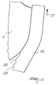
- the particular shape of the active surface 2 constitutes accordingly a guide for the ribbon of substrate 26, the surface fibers 28 of which, shown by way of example in Figure 4, are further slightly pressed before depositing the liquid dispersion and therefore do no tend to separate from said ribbon, accordingly preventing the formation of dust constituted by said fibers.
- the separation of the surface fibers from the ribbon 26 is further limited by the surface treatments performed on the active surface 3, which are intended to reduce the friction and therefore the abrasion, applied to each other by the head 2 and by the ribbon of substrate.
- said dust would be extremely damaging, since as mentioned earlier said dust is highly hygroscopic and by depositing proximate to the first end 10a of the duct 10 it would mix with the liquid part of the dispersion 23, forming deposits capable of hindering correct dosage of the dispersion or even of blocking the duct 10 completely, thus causing an onerous stop of the spreading system.
- the spreader 1 according to the invention by preventing the formation of said dust, is therefore not subjected to these problems, ensuring a deposition of the dispersion 23 on the ribbon 26 that can be dosed with high precision and high uniformity and continuity in operation.
- the head 2 in the long term may be subject to wear, which is in any case minimized by the same factors described above, which allow easy sliding of the ribbon on the head, and in particular by the advantageous shape of the active surface 2.
- the head is in any case worn, it can be replaced easily by simply removing the at least screw 13, disconnecting the head from the footing 14 and inserting a new head.
- the use of one or more gear pumps to feed the dispersion allows a very accurate dosage of the deposit on the ribbon 26 and its real-time control.
- the dispersion 23 can be deposited on the ribbon 26 in multiple parallel longitudinal bands, whereas if the profiles 10b are not provided, said deposition is continuous.
- a spreader having been devised which allows to deposit, in a controlled and efficient manner, an adhesive or a polymeric material in liquid dispersion on a layer of substrate that is constituted by a material made of woven fabric, non-woven fabric, or a mixture thereof, or tissue, even if said substrate has surface fibers that are weakly bonded and therefore can separate easily from it.
- Another object that is achieved by the invention is to require no halting of the machining in order to clean the spreader, accordingly requiring low management costs.
- Another object achieved by the invention is to allow to deposit layers of adhesive or of coating material that have a wide variety of shapes and thicknesses, ensuring accurate control of the thickness of the deposit.
- Another object achieved by the invention is to allow easy maintenance of the device and rapid replacement of any worn components.
Landscapes
- Application Of Or Painting With Fluid Materials (AREA)
- Coating Apparatus (AREA)
Applications Claiming Priority (2)
| Application Number | Priority Date | Filing Date | Title |
|---|---|---|---|
| IT000150A ITTV20030150A1 (it) | 2003-11-26 | 2003-11-26 | Dispositivo di spalmatura, particolarmente per il deposito di adesivi e/o materiali polimerici in dispersione liquida. |
| ITTV20030150 | 2003-11-26 |
Publications (2)
| Publication Number | Publication Date |
|---|---|
| EP1535669A2 true EP1535669A2 (fr) | 2005-06-01 |
| EP1535669A3 EP1535669A3 (fr) | 2006-04-26 |
Family
ID=34452300
Family Applications (1)
| Application Number | Title | Priority Date | Filing Date |
|---|---|---|---|
| EP04027743A Withdrawn EP1535669A3 (fr) | 2003-11-26 | 2004-11-23 | Repandeuse permettant in particulier de déposer des adhésifs et/ou des materiaux polymeres en dispersions dans un liquide |
Country Status (2)
| Country | Link |
|---|---|
| EP (1) | EP1535669A3 (fr) |
| IT (1) | ITTV20030150A1 (fr) |
Cited By (2)
| Publication number | Priority date | Publication date | Assignee | Title |
|---|---|---|---|---|
| CN115213056A (zh) * | 2022-06-10 | 2022-10-21 | 大连理工大学 | 一种涂布条数与宽度可控的狭缝涂布槽模头 |
| CN115970969A (zh) * | 2022-12-31 | 2023-04-18 | 浙江亿帆自动化设备有限公司 | 一种用于针筒的涂胶装置 |
Family Cites Families (3)
| Publication number | Priority date | Publication date | Assignee | Title |
|---|---|---|---|---|
| US4299186A (en) * | 1977-01-17 | 1981-11-10 | International Business Machines Corporation | Method and apparatus for applying a viscous fluid to a substrate |
| JPH07106333B2 (ja) * | 1989-11-28 | 1995-11-15 | 松下電器産業株式会社 | 塗布装置 |
| US5843230A (en) * | 1996-07-02 | 1998-12-01 | Avery Dennison | Sealing system for improved applicator die |
-
2003
- 2003-11-26 IT IT000150A patent/ITTV20030150A1/it unknown
-
2004
- 2004-11-23 EP EP04027743A patent/EP1535669A3/fr not_active Withdrawn
Cited By (3)
| Publication number | Priority date | Publication date | Assignee | Title |
|---|---|---|---|---|
| CN115213056A (zh) * | 2022-06-10 | 2022-10-21 | 大连理工大学 | 一种涂布条数与宽度可控的狭缝涂布槽模头 |
| CN115213056B (zh) * | 2022-06-10 | 2023-08-22 | 大连理工大学 | 一种涂布条数与宽度可控的狭缝涂布槽模头 |
| CN115970969A (zh) * | 2022-12-31 | 2023-04-18 | 浙江亿帆自动化设备有限公司 | 一种用于针筒的涂胶装置 |
Also Published As
| Publication number | Publication date |
|---|---|
| ITTV20030150A1 (it) | 2005-05-27 |
| EP1535669A3 (fr) | 2006-04-26 |
Similar Documents
| Publication | Publication Date | Title |
|---|---|---|
| EP1284855B1 (fr) | Procede et appareil permettant de produire des articles lamines | |
| AU727472B2 (en) | Omega spray pattern and method therefor | |
| DE68926066T2 (de) | Absorbierendes Produkt, Verfahren und Vorrichtung zu seiner Herstellung | |
| JP4226331B2 (ja) | スパッタリング装置 | |
| JP2901661B2 (ja) | 移動するウエブを塗布する装置 | |
| CN107428025B (zh) | 用于均匀分布浆料的装置 | |
| US20060147636A1 (en) | Method and apparatus of forming a coating fluid pattern | |
| CN1708361A (zh) | 施加粘性流体材料的方法及装置 | |
| RU2745016C1 (ru) | Система и способ нанесения клея на движущуюся ленту | |
| EP1088595B1 (fr) | Dispositif pour l'application d'un produit de revêtement abrasif sur une bande en défilement | |
| JP5235343B2 (ja) | 接着剤塗布ノズルおよび接着剤塗布装置 | |
| US20070204793A1 (en) | Nozzle And Filter Arrangement And System For Applying A Fluid Containing Solid Particles To A Substrate | |
| US20140144577A1 (en) | Method for guiding and bonding strands to a substrate | |
| ITFI20090093A1 (it) | Dispositivo per rivestire pannelli rigidi con prodotti liquidi | |
| SK278917B6 (sk) | Spôsob zmiešavania a nanášania lepidla a zariadeni | |
| KR102328514B1 (ko) | 이동중인 베이스 웹 상에 있는 접착제 패턴 | |
| US8286577B2 (en) | Device and method for coating | |
| JP2013040432A (ja) | ノズル装置 | |
| DE2263714C3 (de) | Vorrichtung zum Dosieren von Beschichtungen auf bahnförmigen Materialien | |
| US7326751B2 (en) | Method of thermally processing elastomeric compositions and elastomeric compositions with improved processability | |
| DE112006002587B4 (de) | Vorrichtung zum flächigen Auftragen eines 2-Komponenten Materials auf einen Träger | |
| US9050617B2 (en) | Self-cleaning nozzle for applying adhesive to a moving web | |
| US20080105197A1 (en) | Device for Applying a Coating Material to a Paper Web | |
| CN203514120U (zh) | 涂布机构 | |
| CN119387109B (zh) | 一种医用高分子夹板基布聚氨酯涂敷装置 |
Legal Events
| Date | Code | Title | Description |
|---|---|---|---|
| PUAI | Public reference made under article 153(3) epc to a published international application that has entered the european phase |
Free format text: ORIGINAL CODE: 0009012 |
|
| AK | Designated contracting states |
Kind code of ref document: A2 Designated state(s): AT BE BG CH CY CZ DE DK EE ES FI FR GB GR HU IE IS IT LI LU MC NL PL PT RO SE SI SK TR |
|
| AX | Request for extension of the european patent |
Extension state: AL HR LT LV MK YU |
|
| PUAL | Search report despatched |
Free format text: ORIGINAL CODE: 0009013 |
|
| AK | Designated contracting states |
Kind code of ref document: A3 Designated state(s): AT BE BG CH CY CZ DE DK EE ES FI FR GB GR HU IE IS IT LI LU MC NL PL PT RO SE SI SK TR |
|
| AX | Request for extension of the european patent |
Extension state: AL HR LT LV MK YU |
|
| RIC1 | Information provided on ipc code assigned before grant |
Ipc: B29C 47/14 20060101ALI20060306BHEP Ipc: B05C 5/02 20060101AFI20050304BHEP |
|
| AKX | Designation fees paid | ||
| REG | Reference to a national code |
Ref country code: DE Ref legal event code: 8566 |
|
| STAA | Information on the status of an ep patent application or granted ep patent |
Free format text: STATUS: THE APPLICATION IS DEEMED TO BE WITHDRAWN |
|
| 18D | Application deemed to be withdrawn |
Effective date: 20061027 |