EP1535642A2 - Beissring - Google Patents
Beissring Download PDFInfo
- Publication number
- EP1535642A2 EP1535642A2 EP04028056A EP04028056A EP1535642A2 EP 1535642 A2 EP1535642 A2 EP 1535642A2 EP 04028056 A EP04028056 A EP 04028056A EP 04028056 A EP04028056 A EP 04028056A EP 1535642 A2 EP1535642 A2 EP 1535642A2
- Authority
- EP
- European Patent Office
- Prior art keywords
- tether
- teething ring
- bite
- lip
- sections
- Prior art date
- Legal status (The legal status is an assumption and is not a legal conclusion. Google has not performed a legal analysis and makes no representation as to the accuracy of the status listed.)
- Granted
Links
Images


Classifications
-
- A—HUMAN NECESSITIES
- A61—MEDICAL OR VETERINARY SCIENCE; HYGIENE
- A61M—DEVICES FOR INTRODUCING MEDIA INTO, OR ONTO, THE BODY; DEVICES FOR TRANSDUCING BODY MEDIA OR FOR TAKING MEDIA FROM THE BODY; DEVICES FOR PRODUCING OR ENDING SLEEP OR STUPOR
- A61M16/00—Devices for influencing the respiratory system of patients by gas treatment, e.g. ventilators; Tracheal tubes
- A61M16/04—Tracheal tubes
- A61M16/0488—Mouthpieces; Means for guiding, securing or introducing the tubes
- A61M16/049—Mouthpieces
- A61M16/0493—Mouthpieces with means for protecting the tube from damage caused by the patient's teeth, e.g. bite block
-
- A—HUMAN NECESSITIES
- A61—MEDICAL OR VETERINARY SCIENCE; HYGIENE
- A61M—DEVICES FOR INTRODUCING MEDIA INTO, OR ONTO, THE BODY; DEVICES FOR TRANSDUCING BODY MEDIA OR FOR TAKING MEDIA FROM THE BODY; DEVICES FOR PRODUCING OR ENDING SLEEP OR STUPOR
- A61M16/00—Devices for influencing the respiratory system of patients by gas treatment, e.g. ventilators; Tracheal tubes
- A61M16/04—Tracheal tubes
- A61M16/0488—Mouthpieces; Means for guiding, securing or introducing the tubes
- A61M16/0497—Tube stabilizer
Definitions
- the present invention relates to a teething ring having a passage opening for inserting an instrument into the mouth of a person enclosing Beissube and one on top of each other Side of a median plane of the buffalo from this transverse to the median plane protruding lip shield.
- Teething rings of this type are used in the medical field during treatment or examination of patients used when passing an instrument through the patient's mouth should be inserted into the body.
- Such Instrument may be, for example, an endoscope, a supply tube, a surgical instrument or the like.
- To insert the mouth instrument and during the examination or treatment process to hold in a suitable open position and one Injury of the inserted instrument through the teeth of the patient too Prevent the bite block of the teething ring from entering the patient's mouth Introduced until the lip shield on the upper or lower lips of the patient issue.
- the patient who relies on the often unpleasant introduction of the Instruments reacts with a conscious or unconscious defense reaction while trying, for example, to shut her mouth, gets through prevented the teething ring from biting into the instrument.
- the known teething rings have the disadvantage that they are insufficient the anatomy of different patients are adjusted. So, for example a teething ring, the upper lip shield area in a person with Natural dentition holds back the upper lip and comfortable under the nose rests with a person whose artificial dentition before the procedure was removed, very inconvenient concern, since the then higher upper Lip shield area at the bottom of the nose abuts.
- a teething ring the upper lip shield area at a Patients without dentition is sufficiently high to keep the upper lip reliable is not suitable for a patient with a dentition, as is The upper lip of such a patient may then be above the upper one could push the lip shield area.
- the present invention is based on the object to provide a teething ring of the above type which is simple Way better for use in patients of different Anatomy is adjusted.
- the Beissube of the teething ring based on the middle plane of the Beissube is formed substantially symmetrical
- the Beisstubus based on the median plane is formed substantially symmetrical
- the Lip shield at least at its center located to the Beissube area is lower on one side of the median plane than on its opposite side Page.
- Such a Beisstubus then has one on each side of the median plane Lip shield area, wherein with respect to the median plane of the lip shield areas lower than the other lip shield area. Since the im Patient's mouth absorbable bite tube relative to the median plane is formed substantially symmetrical, is the inventive Teething ring used in a first inserted state, in which one of the lip shield areas on the upper lip of the patient and the other lip shield area rests against the lower lip of the patient, and can also be used in a second inserted state in which the teething ring is inserted opposite the first one Condition along the axis of the passage opening is rotated by 180 °, so that each of the lip shield areas then each other on the other lip Upper lip and lower lip of the patient rests.
- the teething ring in particular the lip shield and the bite block of the teething ring, can in the context of the invention, various of conventional Beissringen known forms or other appropriate facilities exhibit.
- an outer edge of the lower lip shield area has a concave shape and an outer edge of the higher lip shield area has a convex shape.
- Such Design of the lip shield has the advantage that when using the Teething ring in a patient with a denture of the lower lip Part of the lip shield due to the concave shape on both sides of his In each case a wing shield area in the middle of the lipstick area in which the height of the lip shield is larger than in the middle of the buffoon area.
- the lip shield on both sides of the Make concave center plane or a straight or other edge course to choose.
- the Height of the lower lip shield area over a facing bite surface of the bating tube between 2 and 15 mm, preferably between 6 and 12 mm, and the height of the higher lipstick area above a facing bite surface of the buffalo tube between 10 and 30 mm, preferably between 15 and 25 mm.
- the Passage opening of the Beissube at least in the area of the lip shield essentially the cross-sectional shape of a rectangle, in particular one Rectangles whose longer sides are parallel to the median plane.
- the present invention also relates to a Teething ring, in particular one formed in the manner described above Teething ring with a attached or attachable to this or trained tether.
- Teething ring in particular one formed in the manner described above Teething ring with a attached or attachable to this or trained tether.
- straps which are made of an elastic material and along their longitudinal direction having a plurality of holes, which optionally can be hung in Ein Wegab songsing ring to the effective Adjust the length of the tether to the head circumference of the patient.
- the problem arises that the strength the tether is smaller in the areas of the holes and the tethers in use tend to tear in these places. To this Danger must be countered by the overall width or material thickness of the straps be increased, resulting in increased material costs.
- the present invention along the tether a plurality of mounting portions formed by holes or recesses in the tether to be arranged, which at least one Ein yogaabrisk the teething ring are suspended, wherein the width and / or the thickness of the tether in the attachment portions is larger than in the attachment portions adjacent sections of the tether.
- the weakening of the tether in the attachment sections due to the holes or recesses introduced there by a broadening and / or thickening of the tether in this Sections are compensated so that the tether a total of sufficient tear strength with comparatively low material consumption having.
- the invention saves tether material only in areas where no holes or recesses provided are so as to avoid a reduction in tear strength can be.
- the width and / or the Thickness of the tether in the attachment sections and the width and / or the thickness of the tether in the attachment sections adjacent portions of the tether be chosen so that for a Tensile stress along the longitudinal direction of the tether a tear strength the tether in all in the longitudinal direction successive Sections of the tether is substantially the same size. For one given minimum tensile strength can thus a tether with approximately be provided with minimal material consumption.
- the tether according to the invention can then advantageously so be configured that the two longitudinal edges of the tether at least Sectionally in a main plane of the tether so wavy run that sections with greater width and sections with smaller Width alternately merge into each other, with the Attachment sections are provided in the sections of greater width.
- thermoplastic Elastomers TPE
- thermoplastic Elastomers TPE
- latex-free materials TPE
- Thermoplastic elastomers have a high extensibility and good tear resistance and are essentially odorless.
- injection molding process of Advantage.
- the holes or recesses To the material structure, in particular with regard to the tear strength, It is in the area of holes or recesses to improve furthermore advantageous, the holes or recesses also already during the formation of the tether in the injection molding process with.
- the teething ring according to the embodiment shown in Figures 1 to 4 is as a one-piece plastic casting with a tubular Beisstubus 10 and one formed at one end of the Beisstubus 10 Lip shield 12 formed.
- the Beisstubus 10 defines a passage opening 14, through which along a central axis A of the Beisstubus 10 a unillustrated instrument is insertable.
- a median plane M can be defined such that the Center plane M, the central axis A of the passage opening 14 receives, so that the lip shield 12 approximately vertically in the middle substantially cuts.
- the buffing tube 10 is then with respect to this center plane M formed substantially symmetrical. It has approximately the shape of a rectangle in cross section, wherein in the the embodiment shown, the slightly shorter rectangular sides perpendicular run to the median plane M.
- Such a cross-sectional shape of the passage opening 14 may be adapted to the shape of a particular instrument and accordingly, is not limited to the embodiment shown.
- the Beisstubus 10 has this at his the lip plate 12th each end facing away from a semicircular recess 16, to in a conventional manner engaging cutouts for the fingers of the medical To provide staff. Further, at the of the median plane M spaced edge portions of the spaced from the lip shield 12 End of the Beisstubus 10 a tooth shield portion 18 in the form of a formed outside protruding bead.
- the lip shield 12 is approximately perpendicular to the central axis A of the Beisstubus 10 is aligned and resembles an elongated plate whose longitudinal direction oriented parallel to the median plane M and the one bend around the one Central axis A intersecting and perpendicular to the median plane M extending Has axis.
- the lip shield 12 can be divided into two wing sections 20, which in the longitudinal direction of the lip shield 12 on both sides of the passage opening 14 are arranged, as well as a low shield portion 22 and a high shield portion 24, which in perpendicular to the median plane M Direction are arranged on both sides of the passage opening 14.
- the im Essentially identically designed wing sections 20 each have one oval engagement opening 26 through which during the procedure Fingers of the medical staff for positioning the teething ring or the imported instrument or another instrument, for example a suction device is insertable.
- Wing sections 20 At the extreme ends of the Wing sections 20 are also provided Ein stressedabitese 28, at which a led around the head of the patient tether, in particular a later described in more detail inventive tether, can be hung in order to position the teething ring during the procedure hold.
- the low shield portion 22 and the high shield portion 24 are formed so that the height H N of the outer edge 30 of the lower shield portion 22 is less than the height H H of the outer edge 32 of the high shield portion 24.
- the outer The edge 30 of the low shield area 22 has a convex shape so that the height of the rim 30 above the bite bucket 10 at the shield area 22 is minimum and increases toward the wing areas 20 of the lip shield.
- the outer edge 32 of the high lip shield area 24 has a concave shape with respect to the midplane M, so that the height of the rim 32 above the bite tube at the shield area 24 has a maximum and decreases toward the wing areas 26.
- the application of the teething ring according to that shown in Figures 1 to 4 Embodiment of the invention is hereinafter for use in a patient with a natural dentition or during the procedure not removed artificial dentition described.
- the teething ring will be in Direction of the arrow A is inserted into the open mouth of the patient until the Beisstubus 10 substantially completely in the mouth of the patient is absorbed and the lip shield 12 from the outside to the lips in is about.
- the central axis A of the Beisstubus 10 is the teething ring rotated so that the high shield portion 24 near the nose of the Patient is arranged and the low shield portion 22 in the direction of the patient's chin.
- One between an inside 34 of the high Shield area 24 and the tooth shield portion 18 extending portion 38 of the outer wall of the Beisstubus 10 serves as a bite surface 38th for the upper incisors of the patient and one between an inner side 36 of the low shield area 22 and the tooth shield portion 18 extending portion 40 of the outer wall of the teething ring 10 serves as Bite area 40 for the lower incisors of the patient.
- this Beiss vom 38, 40 the teeth of the patient are restrained to damaging or blocking the instrument to be inserted prevent.
- the patient may avoid the teething ring during voluntarily or involuntarily expels the engagement or the teething ring, for example when pulling back the instrument with pulled out.
- the movement of the teething ring in the direction of the arrow A is limited by the fact that the lip shield 12 rests on the lips of the patient, whereby the lower lip of the patient, on which the low shield area 22 abuts, is sufficiently well restrained by the support of the wing areas 20 ,
- the height H H of the high shield area 24 is dimensioned so that in the patient with teeth of the high shield area 24, the upper lip of the patient on the one hand sufficiently covers, on the other hand, however, ends below the nose to an unpleasant pressure or chafing on the underside of the nose reliably to avoid.
- the height H H in this embodiment of the invention is about 17 mm.
- the teething ring according to the invention can optionally also in a patient used, which carries no denture at the time of surgery.
- the teething ring with respect to the central axis A of the Beisstubus 10 so aligned so that the low shield area 22 toward the nose of the patient and the high shield area 24 is directed toward the patient's chin are.
- the underside of the nose is positioned closer to the median plane M than in a patient with a dentition. Accordingly, according to the invention, the low shield area 22 resting on the upper lip in the case of a patient without a bit has a height H N which, on the one hand, enables a reliable covering of the upper lip also for this patient group and, on the other hand, ends the lower shield portion 22 below the nose. A reliable retention of the upper lip is also supported by the wing sections 20.
- the lip plate 12 of the teething ring does not press or rub against the nose.
- the height H N in this embodiment of the invention is about 9 mm.
- the present invention is not limited to the embodiment shown in Figs.
- portions of the bite surfaces 38, 40 may be more inclined toward the lip shield 12. The heights H H and H N should then be measured from the area of the respective base surface against which the teeth or upper jaw rest during normal use.
- Teething ring to hold securely on the patient's head, can be a tether used, which rotates around the head of the patient and to the Hanging sections 28 of the bite ring is mounted.
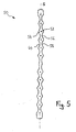
- Fig. 5 is a Tether according to an embodiment of the invention in a non mounted on a teething ring, rolled up in the drawing plane state shown. It has a plurality of longitudinally of the tether arranged distributed holes 52, with which the tether 50 at the Ein vonabêten 28 of the teething ring can be suspended. By choice various of the holes 52, the length of the tether 50 on the Size of the patient's head to be adjusted.
- the holes 52 define attachment portions along the tether 50 54 in the vicinity of the holes 52 and intermediate portions 56, which are arranged between the mounting portions 54.
- the invention Tether 50 is designed so that the transverse to the longitudinal direction of the Tether 50 measured width of the attachment portions 54 is greater as the width of the intermediate sections 56. This is realized by the fact that the longitudinal edges 58, 60 of the tether in a plane corresponding to the drawing Main plane of the tether 50 so wavy, that the tether 50 with respect to an indicated at S in Fig. 5 axis of symmetry is symmetrical.
- the thickness of the tether 50 kept substantially constant over its entire length be, which is beneficial to the wearing experience on the patient's head can affect.
- the Width of the tether over its entire length substantially constant while the thickness of the tether in the Mounting portions is greater than in the remaining sections, in particular the intermediate portions of the tether.
- Such structure may be substantially along the tether at all locations the same tensile strength and the material and Cost of production are minimized.
- the exact shape of the tether of the invention is not limited to the embodiments described in detail. Furthermore can the tether according to the invention not only in context with the teething ring of the present invention but also advantageous be used with other or conventional teething rings.
Landscapes
- Health & Medical Sciences (AREA)
- Pulmonology (AREA)
- Hematology (AREA)
- Life Sciences & Earth Sciences (AREA)
- Engineering & Computer Science (AREA)
- Anesthesiology (AREA)
- Biomedical Technology (AREA)
- Heart & Thoracic Surgery (AREA)
- Otolaryngology (AREA)
- Emergency Medicine (AREA)
- Animal Behavior & Ethology (AREA)
- General Health & Medical Sciences (AREA)
- Public Health (AREA)
- Veterinary Medicine (AREA)
- Orthopedics, Nursing, And Contraception (AREA)
- Dental Tools And Instruments Or Auxiliary Dental Instruments (AREA)
- Surgical Instruments (AREA)
- Hand Tools For Fitting Together And Separating, Or Other Hand Tools (AREA)
Abstract
Description
- Figur 1
- eine Vorderansicht eines Beissrings gemäß einer Ausführungsform der vorliegenden Erfindung,
- Figur 2
- eine Rückansicht des Beissrings,
- Figur 3
- eine perspektivische Rückansicht des Beissrings,
- Figur 4
- eine Seitenansicht des Beissrings und
- Figur 5
- eine Draufsicht auf ein Ausführungsbeispiel eines erfindungsgemäßen Haltebands für einen Beissring.
Claims (8)
- Beissring mit einem eine Durchlassöffnung (14) zum Einführen eines Instruments in den Mund einer Person umschließenden Beisstubus (10) und einem von auf sich gegenüberliegenden Seiten einer Mittelebene (M) des Beisstubus (10) von diesem quer zur Mittelebene (M) abstehenden Lippenschild (12),
dadurch gekennzeichnet, dass
der Beisstubus (10) bezogen auf die Mittelebene (M) im Wesentlichen symmetrisch ausgebildet ist und der Lippenschild (12) zumindest an seinem mittig zum Beisstubus (10) gelegenen Bereich (22, 24) auf einer Seite der Mittelebene niedriger ist als auf seiner gegenüberliegenden Seite. - Beissring nach Anspruch 1, dadurch gekennzeichnet, dass bezüglich der Mittelebene (M) ein äußerer Rand (30) des niedrigeren Lippenschildbereichs (22) eines konkave Form aufweist und ein äußerer Rand (32) des höheren Lippenschildbereichs (24) eine konvexe Form aufweist.
- Beissring nach einem der vorhergehenden Ansprüche, dadurch gekennzeichnet, dass die Höhe (HN) des niedrigeren Lippenschildbereichs (22) über einer zugewandten Beissfläche (40) des Beisstubus (10) zwischen 2 und 15 mm, vorzugsweise zwischen 6 und 12 mm liegt.
- Beissring nach einem der vorhergehenden Ansprüche, dadurch gekennzeichnet, dass die Höhe (HH) des höheren Lippenschildbereichs (24) über einer zugewandten Beissfläche (38) des Beisstubus (10) zwischen 10 und 30 mm, vorzugsweise zwischen 15 und 25 mm liegt.
- Beissring nach einem der vorhergehenden Ansprüche, dadurch gekennzeichnet, dass die Durchlassöffnung (14) des Beisstubus (10) zumindest im Bereich des Lippenschilds (12) im Wesentlichen die Querschnittsform eines Rechtecks, insbesondere eines Rechtecks, dessen längere Seiten parallel zur Mittelebene (M) liegen, aufweist.
- Beissring nach einem der vorhergehenden Ansprüche oder nach dem Oberbegriff des Anspruchs 1, dadurch gekennzeichnet, dass er ein an diesem angebrachtes oder anbringbares oder ausgebildetes Halteband (50) aufweist, wobei entlang des Haltebandes (50) eine Mehrzahl von durch Löcher (52) oder Ausnehmungen in dem Halteband (50) gebildete Anbringungsabschnitte (54) angeordnet sind, welche an mindestens einem Einhängeabschnitt (28) des Beissrings einhängbar sind, und
wobei die Breite oder/und die Dicke des Haltebandes (50) in den Anbringungsabschnitten (54) größer ist als in den Anbringungsabschnitten (54) benachbarten Abschnitten (56) des Haltebandes (50). - Beissring nach Anspruch 6, dadurch gekennzeichnet, dass die Breite oder/und die Dicke des Haltebandes (50) in den Anbringungsabschnitten (54) und die Breite oder/und die Dicke des Haltebandes (50) in den den Anbringungsabschnitten (54) benachbarten Abschnitten (56) des Haltebandes (50) so gewählt sind, dass für eine Zugbeanspruchung entlang der Längsrichtung (S) des Haltebandes (50) eine Reißfestigkeit des Haltebandes (50) in allen in der Längsrichtung aufeinanderfolgenden Abschnitten (54, 56) des Haltebandes (50) im Wesentlichen groß ist.
- Beissring nach Anspruch 6 oder Anspruch 7, dadurch gekennzeichnet, dass die beiden Längsränder (58, 60) des Haltebandes (50) zumindest abschnittsweise in einer Hauptebene des Haltebandes (50) derart wellenförmig verlaufen, dass Abschnitte (54) mit größerer Breite und Abschnitte (56) mit kleinerer Breite abwechselnd ineinander übergehen, wobei die Anbringungsabschnitte (54) in den Abschnitten größerer Breite vorgesehen sind.
Applications Claiming Priority (2)
| Application Number | Priority Date | Filing Date | Title |
|---|---|---|---|
| DE20318238U DE20318238U1 (de) | 2003-11-25 | 2003-11-25 | Beissring |
| DE20318238U | 2003-11-25 |
Publications (3)
| Publication Number | Publication Date |
|---|---|
| EP1535642A2 true EP1535642A2 (de) | 2005-06-01 |
| EP1535642A3 EP1535642A3 (de) | 2005-06-15 |
| EP1535642B1 EP1535642B1 (de) | 2015-08-26 |
Family
ID=34399769
Family Applications (1)
| Application Number | Title | Priority Date | Filing Date |
|---|---|---|---|
| EP04028056.2A Expired - Lifetime EP1535642B1 (de) | 2003-11-25 | 2004-11-25 | Beissring |
Country Status (3)
| Country | Link |
|---|---|
| EP (1) | EP1535642B1 (de) |
| DE (1) | DE20318238U1 (de) |
| ES (1) | ES2551924T3 (de) |
Cited By (2)
| Publication number | Priority date | Publication date | Assignee | Title |
|---|---|---|---|---|
| USD662586S1 (en) | 2011-05-25 | 2012-06-26 | Keymed (Medical & Industrial Equipment) Limited | Mouthpiece for use with endoscope |
| CN108671353A (zh) * | 2018-06-15 | 2018-10-19 | 卜杨 | 一种变径式气管插管固定器 |
Families Citing this family (1)
| Publication number | Priority date | Publication date | Assignee | Title |
|---|---|---|---|---|
| CN114099885A (zh) * | 2021-07-13 | 2022-03-01 | 冯玉玺 | 多用途插管固定器及操作方法 |
Family Cites Families (8)
| Publication number | Priority date | Publication date | Assignee | Title |
|---|---|---|---|---|
| GB1133159A (en) * | 1966-06-24 | 1968-11-13 | Foam Engineers Ltd | Improvements in flexible clips |
| GB1135102A (en) * | 1966-09-16 | 1968-11-27 | Dean Harry Fotou | An improved mouthpiece for use in inhalation therapy |
| US3774616A (en) * | 1972-02-01 | 1973-11-27 | Perry Plastics Inc | Endotracheal tube holder and airway |
| US4502478A (en) * | 1983-04-04 | 1985-03-05 | Lifton Lester J | Medical instrument mouth guard |
| FR2664817B1 (fr) * | 1990-07-17 | 1992-10-23 | Nogueira Braga Francisco | Masque buccal et facial auto-collant pour eviter les contaminations radioactives de l'environnement pendant l'inhalation de produits en radioisotopie clinique. |
| US5174284A (en) * | 1991-09-05 | 1992-12-29 | G.I. Supply, Inc. | Endoscopic bite block |
| US5305742A (en) * | 1992-09-02 | 1994-04-26 | Dale Medical Products, Inc. | Endotracheal tube holder |
| US7077841B2 (en) * | 2001-03-26 | 2006-07-18 | Curon Medical, Inc. | Systems and methods employing a guidewire for positioning and stabilizing external instruments deployed within the body |
-
2003
- 2003-11-25 DE DE20318238U patent/DE20318238U1/de not_active Expired - Lifetime
-
2004
- 2004-11-25 EP EP04028056.2A patent/EP1535642B1/de not_active Expired - Lifetime
- 2004-11-25 ES ES04028056.2T patent/ES2551924T3/es not_active Expired - Lifetime
Cited By (2)
| Publication number | Priority date | Publication date | Assignee | Title |
|---|---|---|---|---|
| USD662586S1 (en) | 2011-05-25 | 2012-06-26 | Keymed (Medical & Industrial Equipment) Limited | Mouthpiece for use with endoscope |
| CN108671353A (zh) * | 2018-06-15 | 2018-10-19 | 卜杨 | 一种变径式气管插管固定器 |
Also Published As
| Publication number | Publication date |
|---|---|
| EP1535642B1 (de) | 2015-08-26 |
| EP1535642A3 (de) | 2005-06-15 |
| ES2551924T3 (es) | 2015-11-24 |
| DE20318238U1 (de) | 2005-03-31 |
Similar Documents
| Publication | Publication Date | Title |
|---|---|---|
| DE69829671T2 (de) | Orales verankerungselement | |
| DE69233224T2 (de) | Verbesserte, hochkantige orthodontische Klammer | |
| DE69126442T2 (de) | Vorrichtung zum vermindern oder verhindern des nächtlichen zusammenpressens und knirschens der zähne sowie des schnarchens | |
| DE3000337A1 (de) | Vorrichtung zum stabilisieren eines nasen- und/oder magenschlauchs o.dgl. | |
| DE102012003564B3 (de) | Vorrichtung zur Verbesserung der Atmung einer Person | |
| DE2648290A1 (de) | Kieferorthopaedisches geraet | |
| CH618864A5 (de) | ||
| CH695235A8 (de) | Lippen- und Wangenexpander. | |
| DE60033185T2 (de) | Bisslöffel mit ausnehmbarem einsatz | |
| EP3941383B1 (de) | Verbesserter lippen- und wangenextruder | |
| DE2616413A1 (de) | Kiefernorthopaedisches band | |
| EP1535642B1 (de) | Beissring | |
| EP1348396B1 (de) | Kofferdam und Kofferdambügel | |
| EP2014327A1 (de) | Tubusfixierung | |
| WO2014032196A1 (de) | Mundeinlage | |
| DE3329919A1 (de) | Lippenschutz | |
| EP4021728A1 (de) | Reinigungsschablone zur zahnreinigung | |
| DE102022134344B4 (de) | Intubationstubusstabilisator | |
| DE102020108709A1 (de) | Absaugvorrichtung zum Absaugen von Flüssigkeit aus einem Mundraum eines Patienten sowie Absaugsystem | |
| DE2830749A1 (de) | Atemmaske | |
| DE2522941A1 (de) | Oralimplantat | |
| DE102008016885B4 (de) | Zungen-Lippen-Gesichtstrainer | |
| DE202009002630U1 (de) | Kompressenfixation | |
| DE202009002417U1 (de) | Nasensplint, Applikator und Nadelhalter zum Einsetzen des Nasensplints zur postoperativen Stabilisierung und Schienung der Nasenscheidewand | |
| DE69418885T2 (de) | Anatomisches, intrabuccales atmungsanschlussstück |
Legal Events
| Date | Code | Title | Description |
|---|---|---|---|
| PUAI | Public reference made under article 153(3) epc to a published international application that has entered the european phase |
Free format text: ORIGINAL CODE: 0009012 |
|
| PUAL | Search report despatched |
Free format text: ORIGINAL CODE: 0009013 |
|
| AK | Designated contracting states |
Kind code of ref document: A2 Designated state(s): AT BE BG CH CY CZ DE DK EE ES FI FR GB GR HU IE IS IT LI LU MC NL PL PT RO SE SI SK TR |
|
| AX | Request for extension of the european patent |
Extension state: AL HR LT LV MK YU |
|
| RIC1 | Information provided on ipc code assigned before grant |
Ipc: 7F 16B 2/08 B Ipc: 7A 61M 16/04 A |
|
| AK | Designated contracting states |
Kind code of ref document: A3 Designated state(s): AT BE BG CH CY CZ DE DK EE ES FI FR GB GR HU IE IS IT LI LU MC NL PL PT RO SE SI SK TR |
|
| AX | Request for extension of the european patent |
Extension state: AL HR LT LV MK YU |
|
| 17P | Request for examination filed |
Effective date: 20051205 |
|
| AKX | Designation fees paid |
Designated state(s): AT BE BG CH CY CZ DE DK EE ES FI FR GB GR HU IE IS IT LI LU MC NL PL PT RO SE SI SK TR |
|
| 17Q | First examination report despatched |
Effective date: 20071114 |
|
| GRAP | Despatch of communication of intention to grant a patent |
Free format text: ORIGINAL CODE: EPIDOSNIGR1 |
|
| INTG | Intention to grant announced |
Effective date: 20150310 |
|
| GRAS | Grant fee paid |
Free format text: ORIGINAL CODE: EPIDOSNIGR3 |
|
| GRAA | (expected) grant |
Free format text: ORIGINAL CODE: 0009210 |
|
| AK | Designated contracting states |
Kind code of ref document: B1 Designated state(s): AT BE BG CH CY CZ DE DK EE ES FI FR GB GR HU IE IS IT LI LU MC NL PL PT RO SE SI SK TR |
|
| REG | Reference to a national code |
Ref country code: GB Ref legal event code: FG4D Free format text: NOT ENGLISH |
|
| REG | Reference to a national code |
Ref country code: CH Ref legal event code: EP |
|
| REG | Reference to a national code |
Ref country code: AT Ref legal event code: REF Ref document number: 744801 Country of ref document: AT Kind code of ref document: T Effective date: 20150915 |
|
| REG | Reference to a national code |
Ref country code: IE Ref legal event code: FG4D Free format text: LANGUAGE OF EP DOCUMENT: GERMAN |
|
| REG | Reference to a national code |
Ref country code: DE Ref legal event code: R096 Ref document number: 502004015002 Country of ref document: DE |
|
| RAP2 | Party data changed (patent owner data changed or rights of a patent transferred) |
Owner name: MASLANKA PATENTVERWALTUNG GMBH |
|
| RIN2 | Information on inventor provided after grant (corrected) |
Inventor name: MASLANKA PATENTVERWALTUNG GMBH |
|
| REG | Reference to a national code |
Ref country code: FR Ref legal event code: PLFP Year of fee payment: 12 |
|
| REG | Reference to a national code |
Ref country code: ES Ref legal event code: FG2A Ref document number: 2551924 Country of ref document: ES Kind code of ref document: T3 Effective date: 20151124 |
|
| PG25 | Lapsed in a contracting state [announced via postgrant information from national office to epo] |
Ref country code: FI Free format text: LAPSE BECAUSE OF FAILURE TO SUBMIT A TRANSLATION OF THE DESCRIPTION OR TO PAY THE FEE WITHIN THE PRESCRIBED TIME-LIMIT Effective date: 20150826 Ref country code: GR Free format text: LAPSE BECAUSE OF FAILURE TO SUBMIT A TRANSLATION OF THE DESCRIPTION OR TO PAY THE FEE WITHIN THE PRESCRIBED TIME-LIMIT Effective date: 20151127 |
|
| REG | Reference to a national code |
Ref country code: NL Ref legal event code: MP Effective date: 20150826 |
|
| PG25 | Lapsed in a contracting state [announced via postgrant information from national office to epo] |
Ref country code: IS Free format text: LAPSE BECAUSE OF FAILURE TO SUBMIT A TRANSLATION OF THE DESCRIPTION OR TO PAY THE FEE WITHIN THE PRESCRIBED TIME-LIMIT Effective date: 20151226 Ref country code: SE Free format text: LAPSE BECAUSE OF FAILURE TO SUBMIT A TRANSLATION OF THE DESCRIPTION OR TO PAY THE FEE WITHIN THE PRESCRIBED TIME-LIMIT Effective date: 20150826 Ref country code: PT Free format text: LAPSE BECAUSE OF FAILURE TO SUBMIT A TRANSLATION OF THE DESCRIPTION OR TO PAY THE FEE WITHIN THE PRESCRIBED TIME-LIMIT Effective date: 20151228 Ref country code: PL Free format text: LAPSE BECAUSE OF FAILURE TO SUBMIT A TRANSLATION OF THE DESCRIPTION OR TO PAY THE FEE WITHIN THE PRESCRIBED TIME-LIMIT Effective date: 20150826 |
|
| PGFP | Annual fee paid to national office [announced via postgrant information from national office to epo] |
Ref country code: AT Payment date: 20151119 Year of fee payment: 12 |
|
| PG25 | Lapsed in a contracting state [announced via postgrant information from national office to epo] |
Ref country code: NL Free format text: LAPSE BECAUSE OF FAILURE TO SUBMIT A TRANSLATION OF THE DESCRIPTION OR TO PAY THE FEE WITHIN THE PRESCRIBED TIME-LIMIT Effective date: 20150826 |
|
| PG25 | Lapsed in a contracting state [announced via postgrant information from national office to epo] |
Ref country code: EE Free format text: LAPSE BECAUSE OF FAILURE TO SUBMIT A TRANSLATION OF THE DESCRIPTION OR TO PAY THE FEE WITHIN THE PRESCRIBED TIME-LIMIT Effective date: 20150826 Ref country code: SK Free format text: LAPSE BECAUSE OF FAILURE TO SUBMIT A TRANSLATION OF THE DESCRIPTION OR TO PAY THE FEE WITHIN THE PRESCRIBED TIME-LIMIT Effective date: 20150826 Ref country code: DK Free format text: LAPSE BECAUSE OF FAILURE TO SUBMIT A TRANSLATION OF THE DESCRIPTION OR TO PAY THE FEE WITHIN THE PRESCRIBED TIME-LIMIT Effective date: 20150826 |
|
| REG | Reference to a national code |
Ref country code: DE Ref legal event code: R097 Ref document number: 502004015002 Country of ref document: DE |
|
| PG25 | Lapsed in a contracting state [announced via postgrant information from national office to epo] |
Ref country code: RO Free format text: LAPSE BECAUSE OF FAILURE TO SUBMIT A TRANSLATION OF THE DESCRIPTION OR TO PAY THE FEE WITHIN THE PRESCRIBED TIME-LIMIT Effective date: 20150826 |
|
| PG25 | Lapsed in a contracting state [announced via postgrant information from national office to epo] |
Ref country code: MC Free format text: LAPSE BECAUSE OF FAILURE TO SUBMIT A TRANSLATION OF THE DESCRIPTION OR TO PAY THE FEE WITHIN THE PRESCRIBED TIME-LIMIT Effective date: 20150826 Ref country code: LU Free format text: LAPSE BECAUSE OF FAILURE TO SUBMIT A TRANSLATION OF THE DESCRIPTION OR TO PAY THE FEE WITHIN THE PRESCRIBED TIME-LIMIT Effective date: 20151125 |
|
| REG | Reference to a national code |
Ref country code: CH Ref legal event code: PL |
|
| PLBE | No opposition filed within time limit |
Free format text: ORIGINAL CODE: 0009261 |
|
| STAA | Information on the status of an ep patent application or granted ep patent |
Free format text: STATUS: NO OPPOSITION FILED WITHIN TIME LIMIT |
|
| PG25 | Lapsed in a contracting state [announced via postgrant information from national office to epo] |
Ref country code: CH Free format text: LAPSE BECAUSE OF NON-PAYMENT OF DUE FEES Effective date: 20151130 Ref country code: LI Free format text: LAPSE BECAUSE OF NON-PAYMENT OF DUE FEES Effective date: 20151130 |
|
| 26N | No opposition filed |
Effective date: 20160530 |
|
| PG25 | Lapsed in a contracting state [announced via postgrant information from national office to epo] |
Ref country code: SI Free format text: LAPSE BECAUSE OF FAILURE TO SUBMIT A TRANSLATION OF THE DESCRIPTION OR TO PAY THE FEE WITHIN THE PRESCRIBED TIME-LIMIT Effective date: 20150826 |
|
| REG | Reference to a national code |
Ref country code: FR Ref legal event code: PLFP Year of fee payment: 13 |
|
| PG25 | Lapsed in a contracting state [announced via postgrant information from national office to epo] |
Ref country code: HU Free format text: LAPSE BECAUSE OF FAILURE TO SUBMIT A TRANSLATION OF THE DESCRIPTION OR TO PAY THE FEE WITHIN THE PRESCRIBED TIME-LIMIT; INVALID AB INITIO Effective date: 20041125 Ref country code: BG Free format text: LAPSE BECAUSE OF FAILURE TO SUBMIT A TRANSLATION OF THE DESCRIPTION OR TO PAY THE FEE WITHIN THE PRESCRIBED TIME-LIMIT Effective date: 20150826 |
|
| PG25 | Lapsed in a contracting state [announced via postgrant information from national office to epo] |
Ref country code: CY Free format text: LAPSE BECAUSE OF FAILURE TO SUBMIT A TRANSLATION OF THE DESCRIPTION OR TO PAY THE FEE WITHIN THE PRESCRIBED TIME-LIMIT Effective date: 20150826 |
|
| REG | Reference to a national code |
Ref country code: AT Ref legal event code: MM01 Ref document number: 744801 Country of ref document: AT Kind code of ref document: T Effective date: 20161125 |
|
| PG25 | Lapsed in a contracting state [announced via postgrant information from national office to epo] |
Ref country code: BE Free format text: LAPSE BECAUSE OF NON-PAYMENT OF DUE FEES Effective date: 20151130 |
|
| PG25 | Lapsed in a contracting state [announced via postgrant information from national office to epo] |
Ref country code: AT Free format text: LAPSE BECAUSE OF NON-PAYMENT OF DUE FEES Effective date: 20161125 Ref country code: TR Free format text: LAPSE BECAUSE OF FAILURE TO SUBMIT A TRANSLATION OF THE DESCRIPTION OR TO PAY THE FEE WITHIN THE PRESCRIBED TIME-LIMIT Effective date: 20150826 |
|
| REG | Reference to a national code |
Ref country code: FR Ref legal event code: PLFP Year of fee payment: 14 |
|
| PGFP | Annual fee paid to national office [announced via postgrant information from national office to epo] |
Ref country code: IE Payment date: 20211119 Year of fee payment: 18 |
|
| PGFP | Annual fee paid to national office [announced via postgrant information from national office to epo] |
Ref country code: CZ Payment date: 20221123 Year of fee payment: 19 |
|
| PG25 | Lapsed in a contracting state [announced via postgrant information from national office to epo] |
Ref country code: IE Free format text: LAPSE BECAUSE OF NON-PAYMENT OF DUE FEES Effective date: 20221125 |
|
| PGFP | Annual fee paid to national office [announced via postgrant information from national office to epo] |
Ref country code: GB Payment date: 20231123 Year of fee payment: 20 |
|
| PGFP | Annual fee paid to national office [announced via postgrant information from national office to epo] |
Ref country code: IT Payment date: 20231124 Year of fee payment: 20 Ref country code: FR Payment date: 20231120 Year of fee payment: 20 Ref country code: DE Payment date: 20231031 Year of fee payment: 20 |
|
| PGFP | Annual fee paid to national office [announced via postgrant information from national office to epo] |
Ref country code: ES Payment date: 20240124 Year of fee payment: 20 |
|
| PG25 | Lapsed in a contracting state [announced via postgrant information from national office to epo] |
Ref country code: CZ Free format text: LAPSE BECAUSE OF NON-PAYMENT OF DUE FEES Effective date: 20231125 |
|
| PG25 | Lapsed in a contracting state [announced via postgrant information from national office to epo] |
Ref country code: CZ Free format text: LAPSE BECAUSE OF NON-PAYMENT OF DUE FEES Effective date: 20231125 |
|
| REG | Reference to a national code |
Ref country code: DE Ref legal event code: R071 Ref document number: 502004015002 Country of ref document: DE |
|
| REG | Reference to a national code |
Ref country code: ES Ref legal event code: FD2A Effective date: 20241202 |
|
| REG | Reference to a national code |
Ref country code: GB Ref legal event code: PE20 Expiry date: 20241124 |
|
| PG25 | Lapsed in a contracting state [announced via postgrant information from national office to epo] |
Ref country code: GB Free format text: LAPSE BECAUSE OF EXPIRATION OF PROTECTION Effective date: 20241124 |
|
| PG25 | Lapsed in a contracting state [announced via postgrant information from national office to epo] |
Ref country code: ES Free format text: LAPSE BECAUSE OF EXPIRATION OF PROTECTION Effective date: 20241126 |
|
| PG25 | Lapsed in a contracting state [announced via postgrant information from national office to epo] |
Ref country code: GB Free format text: LAPSE BECAUSE OF EXPIRATION OF PROTECTION Effective date: 20241124 Ref country code: ES Free format text: LAPSE BECAUSE OF EXPIRATION OF PROTECTION Effective date: 20241126 |