EP1533974A1 - Datenwiedergabesystem und System zur Übertragung von Datenströmen - Google Patents
Datenwiedergabesystem und System zur Übertragung von Datenströmen Download PDFInfo
- Publication number
- EP1533974A1 EP1533974A1 EP04027319A EP04027319A EP1533974A1 EP 1533974 A1 EP1533974 A1 EP 1533974A1 EP 04027319 A EP04027319 A EP 04027319A EP 04027319 A EP04027319 A EP 04027319A EP 1533974 A1 EP1533974 A1 EP 1533974A1
- Authority
- EP
- European Patent Office
- Prior art keywords
- data
- reproducing
- buffer
- target value
- amount
- Prior art date
- Legal status (The legal status is an assumption and is not a legal conclusion. Google has not performed a legal analysis and makes no representation as to the accuracy of the status listed.)
- Granted
Links
- 239000000872 buffer Substances 0.000 claims abstract description 113
- 230000003139 buffering effect Effects 0.000 claims abstract description 23
- 230000007812 deficiency Effects 0.000 claims abstract description 11
- 230000004044 response Effects 0.000 claims abstract description 10
- 238000000034 method Methods 0.000 claims description 19
- 230000005540 biological transmission Effects 0.000 claims description 7
- 230000008569 process Effects 0.000 description 13
- 230000008859 change Effects 0.000 description 7
- 238000001914 filtration Methods 0.000 description 7
- 230000001360 synchronised effect Effects 0.000 description 5
- 238000010586 diagram Methods 0.000 description 4
- 238000006073 displacement reaction Methods 0.000 description 4
- 238000007906 compression Methods 0.000 description 3
- 230000006872 improvement Effects 0.000 description 3
- 230000006835 compression Effects 0.000 description 2
- 230000003111 delayed effect Effects 0.000 description 2
- 230000010355 oscillation Effects 0.000 description 2
- 238000009825 accumulation Methods 0.000 description 1
- 238000004891 communication Methods 0.000 description 1
- 239000013078 crystal Substances 0.000 description 1
- 230000003247 decreasing effect Effects 0.000 description 1
- 230000000694 effects Effects 0.000 description 1
- 230000006870 function Effects 0.000 description 1
- 230000004048 modification Effects 0.000 description 1
- 238000012986 modification Methods 0.000 description 1
- 230000009467 reduction Effects 0.000 description 1
- 238000005070 sampling Methods 0.000 description 1
- 239000004065 semiconductor Substances 0.000 description 1
- 230000005236 sound signal Effects 0.000 description 1
Images



Classifications
-
- H—ELECTRICITY
- H04—ELECTRIC COMMUNICATION TECHNIQUE
- H04L—TRANSMISSION OF DIGITAL INFORMATION, e.g. TELEGRAPHIC COMMUNICATION
- H04L65/00—Network arrangements, protocols or services for supporting real-time applications in data packet communication
- H04L65/1066—Session management
- H04L65/1101—Session protocols
- H04L65/1104—Session initiation protocol [SIP]
-
- H—ELECTRICITY
- H04—ELECTRIC COMMUNICATION TECHNIQUE
- H04L—TRANSMISSION OF DIGITAL INFORMATION, e.g. TELEGRAPHIC COMMUNICATION
- H04L65/00—Network arrangements, protocols or services for supporting real-time applications in data packet communication
- H04L65/1066—Session management
- H04L65/1101—Session protocols
Definitions
- Non-Patent Literature 1
- Respective clients can receive the audio data that the server system streaming-outputs to the network, and then reproduce such data.
- the invention is characterized by having the following arrangement.
- a data reproducing system of the present invention includes:
- the reproducing speed is synchronized with the streaming speed of the audio data that are streaming- distributed via the network.
- the audio data are buffered up to the target value prior to the reproducing start, and then the reproducing speed is controlled to maintain an amount of buffer at the target value. Therefore, even if the basic clock of the audio reproducing system is different from the data reading speed of the server system as the streaming-distributor, both are mated with each other by the reproducing speed control.
- the reproducing speeds of all audio reproducing systems can be synchronized with the streaming speed of the same audio data. Therefore, the music can be reproduced in synchronism with each other.
- the reproducing speed can be mated with the audio data being streamed via the network by maintaining the amount of buffer at the target value, if viewed in broad perspective.
- the filtering process may be applied to the parameter indicating the excess and deficiency in the amount of the buffer to give a time constant (inertia). Then, the reproducing speed (clock frequency) may be controlled by the parameter that is subjected to the filtering process.
- the means for controlling the reproducing speed controls the reproducing speed within predetermined upper and lower limits of the reproducing speed even if the excess and deficiency of the amount of buffer is increased.
- the reproducing speed is largely changed even in the case where an amount of buffer is extremely increased and extremely decreased, the frequency change occurs to such an extent that the user can discriminate such frequency change through the sense of hearing. Therefore, even if the extreme buffer change is caused, the excess and deficiency is dissolved gradually by controlling the reproducing speed within a predetermined range.
- the setting of the upper limit and the lower limit of the reproducing speed can be replaced with the setting of the upper limit and the lower limit of the reproducing speed control parameter (the upper limit and the lower limit of the parameter are decided in the embodiment described later).
- the means for controlling the reproducing speed stops the reproducing of the reproducing unit when the deficiency of the amount of buffer in the buffering device is in excess of a predetermined value, and keeps reproducing stop until data are buffered in the buffering device to exceed the target value.
- An audio streaming system of the present invention comprises a server system for streaming-outputting audio data to a network; and a plurality of audio reproducing systems each of which are set forth in Claim 1, Claim 2, or Claim 3 as a client system.
- all the client systems can reproduce the audio data that are streaming-output from the server system onto the network in synchronism.
- the audio data that are streaming-output from the server system onto the network are to be reproduced simultaneously in a plurality of audio reproducing systems (client systems)
- client systems if only the process of controlling the reading speed to maintain an amount of buffer of the audio data, which are streaming-distributed (from the server system), at the target value is carried out in the audio reproducing system (client system) without introduction of improvements (improvements in precision of the NTP server and the clock generator circuit) into the hard ware, the reproducing rate of the audio reproducing system can be mated with the streaming rate of the audio data that are streaming-distributed and also the reproducing speed and the reproducing position can be synchronized mutually in all audio reproducing systems even though a plurality of audio reproducing systems are connected to the network.
- FIG.1 is a view showing a configuration of an audio streaming system as an embodiment of the present invention.
- a server system 1 is connected to a plurality of client systems 2 via a LAN (Local Area Network) 3.
- the LAN 3 may be constituted by either wired LAN or wireless LAN.
- the server system is provided with an A/D converter (not shown) for digitalizing the analog signal and designed to digitalize the signal before distributing the data to each client system 2 at the latest.
- a speaker system 4 is connected to the server system 1, and a speaker system 5 is connected to each client system 2.
- the server system 1 has a built-in storage such as a hard disk, or the like, and stores a large number of digitized audio data (music data) therein.
- the user can select the music from the audio data (musical pieces) stored in the server system 1 and reproduce the selected music independently from the server system 1 and other client systems 2.
- the server system 1 can reproduce the music selected independently.
- the selection of music is executed by using the infrared remote controller (not shown).
- the music selected in the server system 1 is broadcast to all the client systems 2, and thus the same music is reproduced in synchronism in all the client systems 2.
- FIG.2 is a block diagram of signal path systems of the server system 1 and the client system 2.
- the server system 1 has a hard disk 10 that accumulates/stores the audio data therein in the linear PCM system.
- a FIFO 11 is a buffer that is used to control the reading from the hard disk 10.
- the audio data of the requested music are read in response to a sampling clock of the server system and then input into an encoder 12.
- the encoder 12 MP3(MPEG Audio Layer(ISO/IEC 11172-3 and ISO/IEC 13818-3))-compresses the audio data and then input the compressed data into a network interface 13.
- MP3 MPEG Audio Layer(ISO/IEC 11172-3 and ISO/IEC 13818-3)
- other audio compression techniques for example, AC-3, AAC, ATRAC
- the audio data is stored in the hard disk 10 in the linear PCM system
- compression data such as MP3 data that is compressed in advance may be stored in the hard disk 10, and both the linear PCM data and MP3 data may be stored therein.
- the network interface 13 sends out the MP3-compressed audio data to the LAN 3.
- the server system 1 itself reproduces the audio data that are sent out onto the LAN 3. For this reason, a buffering device (FIFO(2) 15, buffer 16, FIFO(3) 17) buffers the audio data by an amount of buffer and an amount of transmission delay in the client system 2 to delay the data up to the same timing as the reproducing timing in the client system 2, and then the delayed data are input into an audio output circuit 18.
- the audio output circuit 18 DA-converts and amplifies the audio data and then outputs resultant data to the speaker system 4.
- a quantity of data that are buffered by the buffering device corresponds to a reproducing time of almost 2 sec.
- the hard disk is used as the buffer 16 since such data are the linear PCM data.
- this buffer is provided to mate the reproducing timing in the server system 1 with a lag in the reproducing in the client system 2.
- an amount of buffer and the transmission delay in the buffer may be decided in response to those in the client system 2.
- the transmission delay, throughput in the encoder 12 and the decoder 23, etc. may be considered.
- the client system 2 includes a CPU 20, a VCXO (Voltage Controlled Crystal Oscillator) 21, a buffer 22, a decoder (DSP) 23, a network interface 24, and an audio output circuit 25.
- the network interface 24 is connected to the LAN 3, and receives the audio data that are output from the server system 1 (and are subjected to the MP3-compression).
- the procedure of transmitting the audio data from the server system 1 to the client system 2 contains the retransmission control.
- the TCP protocol is employed.
- the UDP User Datagram Protocol
- the retransmission control is executed in the upper layer.
- the decoder 23 decodes the MP3-compressed audio data, which are read from the buffer 22, into the linear PCM, then converts the decoded data into the analog signal, and then outputs such signal to the audio output circuit 25.
- This audio output circuit 25 amplifies the audio signal and then outputs the amplified signal to the speaker system 5.
- the CPU 20 monitors an amount of buffer in the buffer 22. Then, a read amount from the buffer 22 is controlled by controlling a clock frequency of the VCXO 21, which supplies a clock signal to the decoder 23, so as to keep an amount of buffer constant (at a target value). This control of the clock frequency of the VCXO 21 is performed within a range in which the user does not sense a frequency variation through the sense of hearing.
- an amount of buffer in the buffer 22 is maintained at a predetermined value (target value)
- the reproducing speed and the reproduced position in the client system can be synchronized with the data output speed and the output timing in the server system 1.
- target value a predetermined value
- an amount of buffer can be maintaining at a predetermined amount on an average to take the synchronization of the reproducing timing, if viewed in broad perspective, because the server system 1 sends out the audio data periodically based on the precise clock signal.
- FIG.3 is a view explaining a relationship between a quantity of audio data accumulated in the buffer 22 (buffer remaining capacity) and a clock control parameter.
- the CPU 20 decides the reproducing speed control parameter such that a remaining capacity of the buffer 22 coincides with the target value.
- the CPU 20 receives a group of packets every 500 ms during the reproducing of the music, and checks the buffer remaining capacity every reception. Upon starting the music, the audio data are accumulated in the buffer 22 without reproducing of the music. Then, the reproducing of the audio data are started when the audio data are buffered up to a buffer value B0 that exceeds the target value by a predetermined level (T0). In this case, B0 is given as a level that exceeds the target value of the buffer by an amount of initial consumption of the decoder.
- the target value of the buffer is decided based on a predetermined reproducing time (2 sec)X a bit rate of MP3.
- a parameter dn is decided in response to a buffer remaining capacity Bn that is checked every about 500 ms. Then, the VCXO 21 is controlled in response to this dn to decide a reproducing speed (clock frequency).
- a difference component (a value corresponding to this) from the target value is output as a parameter d1.
- the VCXO 21 is controlled based on the parameter d1 to slow the clock.
- this difference component (a value corresponding to this) is output as a parameter d3.
- this check result of the buffer remaining capacity is decided as a reliable value.
- this difference component (a value corresponding to this) is output as a parameter d6 because the difference component of the buffer remaining capacity from the target value is within the control range.
- this lower limit value (a value corresponding to this) is output as a parameter d7.
- the parameter dn is decided in response to this difference value and output when the buffer remaining capacity Bn is within a range of ⁇ 300 B from the target value (control range), while the parameter is decided based on the upper limit value or the lower limit value of the control range and output when the buffer remaining capacity is out of the control range on the upper side or the lower side.
- the server system 1 transmits a group of packets every 500 ms, but the arrival time to the client system 2 is varied because of transmission delay, or the like. If a time difference of an incoming time of the current packet (a time at which a head packet of the packet group arrives at) from an incoming time of the preceding packet is within ⁇ 10 % of 500 ms ( ⁇ 50 ms), such incoming time is decided as a normal incoming time and then this check of the buffer remaining capacity is made effective. Thus, the parameter dn is decided based on this check result.
- the above target value and the processing procedures are set similarly in a plurality of client systems 2 shown in FIG.1.
- an amount of buffer is kept to the almost same value in respective client systems and therefore the same reproducing position of the same audio data can be reproduced at the same reproducing speed in respective client systems.
- variation in a default oscillation frequency of the VCXO 21 in the client systems 2 can be absorbed by the buffer remaining capacity control. As a result, all the client systems 2 can reproduce the audio data in synchronism at the same clock frequency.
- FIG.4 is a functional block diagram explaining a filtering process executed by the CPU 20.
- the difference component (the value based on this component) of the remaining capacity of the buffer 22 from the target value is used as the parameter to control the frequency of the VCXO 21.
- this parameter is input directly into the VCXO 21
- the clock frequency is changed discretely and abruptly and thus it is possible that the user feels the unnaturalness through the sense of hearing.
- the filtering process is applied to this difference component (parameter) to give a time constant (inertia) and then the resultant difference component is input into the VCXO 21.
- the reproducing speed control parameter to be input into the VCXO 21 at this time is obtained by adding a value obtained by multiplying the current parameter by a coefficient A and a value obtained by multiplying the preceding parameter (output of Z) by a coefficient B.
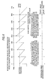
- FIG.5 shows change in the buffer remaining capacity and change in the clock frequency in the case where the reproducing speed in the client system 2 is quicker than the reading speed in the server system 1.
- the reproducing speed is quicker than the reading speed
- a quantity of data consumed (reproduced) in the client system is larger than a quantity of data accumulated in the buffer 22, and thus the buffer remaining capacity is reduced gradually.
- the clock frequency oscillated by the VCXO 21 is controlled gradually lower to slow the reproducing speed, and thus a reading amount is reduced.
- reduction in the buffer remaining capacity is stopped and the buffer remaining capacity is increased gradually toward the target value.
- FIG. 6 shows change in the buffer remaining capacity and change in the clock frequency in the case where the reproducing speed in the client system 2 is slower than the reading speed in the server system 1.
- the reproducing speed is slower than the reading speed
- a quantity of data consumed (reproduced) in the client system is smaller than a quantity of data accumulated in the buffer 22, and thus the buffer remaining capacity is increased gradually.
- the clock frequency oscillated by the VCXO 21 is controlled gradually higher to quicken the reproducing speed, and thus a reading amount is increased.
- increase in the buffer remaining capacity is stopped and then the buffer remaining capacity is reduced gradually toward the target value.
- FIG.7 is a flowchart showing operations of the client system 2 in the broadcast mode. If the reproducing is started in the broadcast mode, first only the reception of the audio data is executed without reproducing and the audio data are buffered in the buffer 22 up to B0. If this buffering is completed (s1), the CPU 20 instructs the decoder 23 to read the audio data buffered in the buffer 22 and to start the reproducing (s2).
- the detected buffer remaining capacity is rounded off within the control range (s8) , and the reproducing speed control parameter is calculated by inputting the buffer remaining capacity (parameter based on this capacity) into the filter in FIG.4 (s10).
- the rounding process rounds off the value of the buffer remaining capacity within ⁇ 300 B not to vary excessively the reproducing speed when the buffer remaining capacity is shifted from the target value to exceed ⁇ 300 B (in the case of 160 kbps).
- the reproducing speed control parameter output from the filter is set on the VCXO 21 (s11).
- the current incoming time of the packets is displaced from the preceding incoming time of the packets by ⁇ 10 % or more of the reference interval of 500 ms (s7), the current check result of the buffer remaining capacity is not employed and the preceding buffer remaining capacity is set once again (s9), and then the process goes to the reproducing speed control parameter calculating process in s10. Even though the same buffer remaining capacity is input plural times, the reproducing speed control parameter that is output is varied by the time constant of the filter.
- each client system 2 can escape independently from the broadcast mode and can issue the request of another music (audio data) to the server system 1 to reproduce.
- the client system that receives the broadcast distribution are not always prepared as the entire client systems that are connected to the LAN 3.
- One or plural client systems out of them may be employed.
- the present invention intends to keep the reproducing synchronization between the client systems that are now receiving the broadcast distribution and the client systems 2 the server system 1.
- the data to be produced in synchronism is not limited to the audio data described above, and the present invention can be also applied to any kind of data that is necessary to be reproduced in synchronism.
- the LAN 3 is employed for a data transmission between the server system 1 and the client systems 2, any other communication methods can be employed, for example, Internet and the like.
Landscapes
- Engineering & Computer Science (AREA)
- Business, Economics & Management (AREA)
- General Business, Economics & Management (AREA)
- Multimedia (AREA)
- Computer Networks & Wireless Communication (AREA)
- Signal Processing (AREA)
- Reverberation, Karaoke And Other Acoustics (AREA)
- Data Exchanges In Wide-Area Networks (AREA)
- Communication Control (AREA)
Applications Claiming Priority (2)
| Application Number | Priority Date | Filing Date | Title |
|---|---|---|---|
| JP2003388348 | 2003-11-18 | ||
| JP2003388348A JP4289129B2 (ja) | 2003-11-18 | 2003-11-18 | オーディオ配信システム |
Publications (2)
| Publication Number | Publication Date |
|---|---|
| EP1533974A1 true EP1533974A1 (de) | 2005-05-25 |
| EP1533974B1 EP1533974B1 (de) | 2007-09-19 |
Family
ID=34431551
Family Applications (1)
| Application Number | Title | Priority Date | Filing Date |
|---|---|---|---|
| EP04027319A Ceased EP1533974B1 (de) | 2003-11-18 | 2004-11-17 | Datenwiedergabesystem und System zur Übertragung von Datenströmen |
Country Status (4)
| Country | Link |
|---|---|
| US (1) | US7769476B2 (de) |
| EP (1) | EP1533974B1 (de) |
| JP (1) | JP4289129B2 (de) |
| DE (1) | DE602004009024T2 (de) |
Cited By (1)
| Publication number | Priority date | Publication date | Assignee | Title |
|---|---|---|---|---|
| WO2008035164A3 (en) * | 2006-09-19 | 2008-09-12 | Rai Radiotelevisione Italiana | Method and apparatus for reproducing an audio video sequence |
Families Citing this family (12)
| Publication number | Priority date | Publication date | Assignee | Title |
|---|---|---|---|---|
| US7809452B2 (en) * | 2005-02-23 | 2010-10-05 | Leviton Manufacturing Co., Inc. | Delay management of presentation output system and method |
| GB2429573A (en) * | 2005-08-23 | 2007-02-28 | Digifi Ltd | Multiple input and output media playing network |
| JP2007086484A (ja) * | 2005-09-22 | 2007-04-05 | Brother Ind Ltd | コンテンツ配信システム及びコンテンツ配信方法並びにそれに用いる配信装置、端末装置及びそのプログラム |
| US8310965B1 (en) * | 2005-10-04 | 2012-11-13 | Marvell International Ltd. | Buffered audio system with synchronizing bus controller |
| WO2008004193A2 (en) * | 2006-07-04 | 2008-01-10 | Nxp B.V. | Method for controlling a receiver system and receiver system, in particular for wireless ip datacast |
| US7787486B2 (en) * | 2006-11-13 | 2010-08-31 | Honeywell International Inc. | Method and system for achieving low jitter in real-time switched networks |
| US20090089813A1 (en) * | 2007-10-02 | 2009-04-02 | Conexant Systems, Inc. | Method and system for dynamic audio stream redirection |
| US8656415B2 (en) * | 2007-10-02 | 2014-02-18 | Conexant Systems, Inc. | Method and system for removal of clicks and noise in a redirected audio stream |
| US8578382B2 (en) * | 2009-05-19 | 2013-11-05 | Qualcomm Incorporated | Associating data for events occurring in software threads with synchronized clock cycle counters |
| JP5397495B2 (ja) * | 2012-04-03 | 2014-01-22 | ヤマハ株式会社 | データ配信システムおよび中継装置 |
| JP6693066B2 (ja) | 2015-08-18 | 2020-05-13 | ヤマハ株式会社 | 制御装置 |
| JP6582722B2 (ja) | 2015-08-19 | 2019-10-02 | ヤマハ株式会社 | コンテンツ配信装置 |
Citations (2)
| Publication number | Priority date | Publication date | Assignee | Title |
|---|---|---|---|---|
| US5699481A (en) * | 1995-05-18 | 1997-12-16 | Rockwell International Corporation | Timing recovery scheme for packet speech in multiplexing environment of voice with data applications |
| US20020040403A1 (en) * | 1999-05-04 | 2002-04-04 | Richard S. Goldhor | Method and apparatus for providing continuous playback or distribution of audio and audio-visual streamed multimedia received over networks having non-deterministic delays |
Family Cites Families (12)
| Publication number | Priority date | Publication date | Assignee | Title |
|---|---|---|---|---|
| CA2140850C (en) * | 1994-02-24 | 1999-09-21 | Howard Paul Katseff | Networked system for display of multimedia presentations |
| US5825771A (en) * | 1994-11-10 | 1998-10-20 | Vocaltec Ltd. | Audio transceiver |
| US5809454A (en) * | 1995-06-30 | 1998-09-15 | Sanyo Electric Co., Ltd. | Audio reproducing apparatus having voice speed converting function |
| JPH09261613A (ja) | 1996-03-26 | 1997-10-03 | Mitsubishi Electric Corp | データ受信再生装置 |
| US6151076A (en) * | 1998-02-10 | 2000-11-21 | Tektronix, Inc. | System for phase-locking a clock to a digital audio signal embedded in a digital video signal |
| JP3211771B2 (ja) * | 1998-05-26 | 2001-09-25 | 日本電気株式会社 | 音声送受信装置 |
| US6249810B1 (en) * | 1999-02-19 | 2001-06-19 | Chaincast, Inc. | Method and system for implementing an internet radio device for receiving and/or transmitting media information |
| US6347380B1 (en) * | 1999-03-03 | 2002-02-12 | Kc Technology, Inc. | System for adjusting clock rate to avoid audio data overflow and underrun |
| US6665751B1 (en) * | 1999-04-17 | 2003-12-16 | International Business Machines Corporation | Streaming media player varying a play speed from an original to a maximum allowable slowdown proportionally in accordance with a buffer state |
| US6377931B1 (en) * | 1999-09-28 | 2002-04-23 | Mindspeed Technologies | Speech manipulation for continuous speech playback over a packet network |
| SE517156C2 (sv) * | 1999-12-28 | 2002-04-23 | Global Ip Sound Ab | System för överföring av ljud över paketförmedlade nät |
| JP2004221951A (ja) * | 2003-01-15 | 2004-08-05 | Alps Electric Co Ltd | 伝送データのジッター補正方法 |
-
2003
- 2003-11-18 JP JP2003388348A patent/JP4289129B2/ja not_active Expired - Fee Related
-
2004
- 2004-11-17 US US10/991,823 patent/US7769476B2/en active Active
- 2004-11-17 EP EP04027319A patent/EP1533974B1/de not_active Ceased
- 2004-11-17 DE DE602004009024T patent/DE602004009024T2/de not_active Expired - Lifetime
Patent Citations (2)
| Publication number | Priority date | Publication date | Assignee | Title |
|---|---|---|---|---|
| US5699481A (en) * | 1995-05-18 | 1997-12-16 | Rockwell International Corporation | Timing recovery scheme for packet speech in multiplexing environment of voice with data applications |
| US20020040403A1 (en) * | 1999-05-04 | 2002-04-04 | Richard S. Goldhor | Method and apparatus for providing continuous playback or distribution of audio and audio-visual streamed multimedia received over networks having non-deterministic delays |
Non-Patent Citations (2)
| Title |
|---|
| JINYONG JO, YOONYOUNG KIM AND JONGWON KIM: "Integration of Error Recovery and Adaptive Playout for Enhanced Multicast Media Streaming", NETWORKED MEDIA LAB., DEPARTMENT OF INFORMATION AND COMMUNICATIONS, September 2003 (2003-09-01), pages 1 - 12, XP002311360, Retrieved from the Internet <URL:http://netmedia.kjist.ac.kr/old_home/jongwon/papers/2002pa-jinyong.pdf> * |
| LAOUTARIS N ET AL: "Intrastream synchronizuation for continuous media streams: a survey of playout schedulers", IEEE NETWORK, IEEE INC. NEW YORK, US, vol. 16, no. 3, May 2002 (2002-05-01), pages 30 - 40, XP002256212, ISSN: 0890-8044 * |
Cited By (5)
| Publication number | Priority date | Publication date | Assignee | Title |
|---|---|---|---|---|
| WO2008035164A3 (en) * | 2006-09-19 | 2008-09-12 | Rai Radiotelevisione Italiana | Method and apparatus for reproducing an audio video sequence |
| EP2070310A2 (de) * | 2006-09-19 | 2009-06-17 | Rai Radiotelevisione Italiana S.p.A. | Verfahren und vorrichtung zur wiedergabe einer audio-video-sequenz |
| US20100061698A1 (en) * | 2006-09-19 | 2010-03-11 | Alberto Morello | Method for reproducing an audio and/or video sequence, a reproducing device and reproducing apparatus using the method |
| CN101518048B (zh) * | 2006-09-19 | 2012-04-11 | Rai意大利无线电视股份有限公司 | 用于再生音视频序列的方法与设备 |
| US9338492B2 (en) | 2006-09-19 | 2016-05-10 | Rai Radiotelevisione Italiana S.P.A. | Method for reproducing an audio and/or video sequence, a reproducing device and reproducing apparatus using the method |
Also Published As
| Publication number | Publication date |
|---|---|
| JP2005148565A (ja) | 2005-06-09 |
| US20050138666A1 (en) | 2005-06-23 |
| DE602004009024D1 (de) | 2007-10-31 |
| JP4289129B2 (ja) | 2009-07-01 |
| EP1533974B1 (de) | 2007-09-19 |
| US7769476B2 (en) | 2010-08-03 |
| DE602004009024T2 (de) | 2008-06-19 |
Similar Documents
| Publication | Publication Date | Title |
|---|---|---|
| EP1398931B1 (de) | Synchrones Abspielen von Medien-Paketen | |
| US10809969B2 (en) | Systems and methods for audio playback | |
| US10298639B2 (en) | Streaming media delivery system | |
| US7769476B2 (en) | Data reproducing system and data streaming system | |
| US8185611B2 (en) | Streaming media delivery system | |
| US7243150B2 (en) | Reducing the access delay for transmitting processed data over transmission data | |
| US9621682B2 (en) | Reduced latency media distribution system | |
| JP2008522468A (ja) | ネットワーク上のマルチチャネルスピーカの同期 | |
| JP2010538539A (ja) | 相互接続ネットワークにおける関連データストリームの同期 | |
| JP2011234421A (ja) | 確率的なネットワーク上のメッセージの同期化 | |
| FR2920930A1 (fr) | Systeme synchronise de distribution et de traitement de signaux,notamment de signaux audio dans un reseau d'enceintes sans fil | |
| EP1672870A1 (de) | System und Verfahren zur Steuerung der Datenübertragungsrate eines Echtzeitdatenstromdienstes | |
| JP2003179662A (ja) | データ通信システム、データ送信装置、データ受信装置、および方法、並びにコンピュータ・プログラム | |
| JP2003259365A (ja) | データストリーム処理装置 | |
| JP6582722B2 (ja) | コンテンツ配信装置 | |
| JPH0630043A (ja) | 音声パケット通信方式 | |
| JP4742836B2 (ja) | 受信装置 | |
| JP4971705B2 (ja) | コンテンツ受信装置、コンテンツ送信装置、基本データ同期方法及びコンテンツ受信プログラム | |
| JP2007274536A (ja) | 受信装置及び送受信方法 |
Legal Events
| Date | Code | Title | Description |
|---|---|---|---|
| PUAI | Public reference made under article 153(3) epc to a published international application that has entered the european phase |
Free format text: ORIGINAL CODE: 0009012 |
|
| AK | Designated contracting states |
Kind code of ref document: A1 Designated state(s): AT BE BG CH CY CZ DE DK EE ES FI FR GB GR HU IE IS IT LI LU MC NL PL PT RO SE SI SK TR |
|
| AX | Request for extension of the european patent |
Extension state: AL HR LT LV MK YU |
|
| 17P | Request for examination filed |
Effective date: 20051122 |
|
| AKX | Designation fees paid |
Designated state(s): DE FR GB |
|
| 17Q | First examination report despatched |
Effective date: 20051216 |
|
| GRAP | Despatch of communication of intention to grant a patent |
Free format text: ORIGINAL CODE: EPIDOSNIGR1 |
|
| RAP1 | Party data changed (applicant data changed or rights of an application transferred) |
Owner name: YAMAHA CORPORATION |
|
| GRAS | Grant fee paid |
Free format text: ORIGINAL CODE: EPIDOSNIGR3 |
|
| GRAA | (expected) grant |
Free format text: ORIGINAL CODE: 0009210 |
|
| AK | Designated contracting states |
Kind code of ref document: B1 Designated state(s): DE FR GB |
|
| REG | Reference to a national code |
Ref country code: GB Ref legal event code: FG4D |
|
| REF | Corresponds to: |
Ref document number: 602004009024 Country of ref document: DE Date of ref document: 20071031 Kind code of ref document: P |
|
| ET | Fr: translation filed | ||
| PLBE | No opposition filed within time limit |
Free format text: ORIGINAL CODE: 0009261 |
|
| STAA | Information on the status of an ep patent application or granted ep patent |
Free format text: STATUS: NO OPPOSITION FILED WITHIN TIME LIMIT |
|
| 26N | No opposition filed |
Effective date: 20080620 |
|
| REG | Reference to a national code |
Ref country code: FR Ref legal event code: PLFP Year of fee payment: 12 |
|
| REG | Reference to a national code |
Ref country code: FR Ref legal event code: PLFP Year of fee payment: 13 |
|
| REG | Reference to a national code |
Ref country code: FR Ref legal event code: PLFP Year of fee payment: 14 |
|
| REG | Reference to a national code |
Ref country code: DE Ref legal event code: R079 Ref document number: 602004009024 Country of ref document: DE Free format text: PREVIOUS MAIN CLASS: H04L0029060000 Ipc: H04L0065000000 |
|
| PGFP | Annual fee paid to national office [announced via postgrant information from national office to epo] |
Ref country code: GB Payment date: 20211118 Year of fee payment: 18 Ref country code: FR Payment date: 20211122 Year of fee payment: 18 |
|
| PGFP | Annual fee paid to national office [announced via postgrant information from national office to epo] |
Ref country code: DE Payment date: 20220620 Year of fee payment: 19 |
|
| GBPC | Gb: european patent ceased through non-payment of renewal fee |
Effective date: 20221117 |
|
| PG25 | Lapsed in a contracting state [announced via postgrant information from national office to epo] |
Ref country code: GB Free format text: LAPSE BECAUSE OF NON-PAYMENT OF DUE FEES Effective date: 20221117 |
|
| PG25 | Lapsed in a contracting state [announced via postgrant information from national office to epo] |
Ref country code: FR Free format text: LAPSE BECAUSE OF NON-PAYMENT OF DUE FEES Effective date: 20221130 |
|
| REG | Reference to a national code |
Ref country code: DE Ref legal event code: R119 Ref document number: 602004009024 Country of ref document: DE |
|
| PG25 | Lapsed in a contracting state [announced via postgrant information from national office to epo] |
Ref country code: DE Free format text: LAPSE BECAUSE OF NON-PAYMENT OF DUE FEES Effective date: 20240601 |
|
| PG25 | Lapsed in a contracting state [announced via postgrant information from national office to epo] |
Ref country code: DE Free format text: LAPSE BECAUSE OF NON-PAYMENT OF DUE FEES Effective date: 20240601 |