EP1533892B9 - Verfahren zum Reduzieren der Auslaufzeit eines Elektromotors - Google Patents
Verfahren zum Reduzieren der Auslaufzeit eines Elektromotors Download PDFInfo
- Publication number
- EP1533892B9 EP1533892B9 EP03025988A EP03025988A EP1533892B9 EP 1533892 B9 EP1533892 B9 EP 1533892B9 EP 03025988 A EP03025988 A EP 03025988A EP 03025988 A EP03025988 A EP 03025988A EP 1533892 B9 EP1533892 B9 EP 1533892B9
- Authority
- EP
- European Patent Office
- Prior art keywords
- winding
- short circuit
- switching elements
- circuit
- short
- Prior art date
- Legal status (The legal status is an assumption and is not a legal conclusion. Google has not performed a legal analysis and makes no representation as to the accuracy of the status listed.)
- Expired - Lifetime
Links
- 238000000034 method Methods 0.000 title claims description 25
- 238000004804 winding Methods 0.000 claims abstract description 49
- 230000001052 transient effect Effects 0.000 claims description 5
- 230000002459 sustained effect Effects 0.000 claims 1
- 230000001960 triggered effect Effects 0.000 abstract 1
- 230000007704 transition Effects 0.000 description 6
- 230000008901 benefit Effects 0.000 description 3
- 230000005347 demagnetization Effects 0.000 description 3
- 230000001419 dependent effect Effects 0.000 description 3
- XEEYBQQBJWHFJM-UHFFFAOYSA-N Iron Chemical compound [Fe] XEEYBQQBJWHFJM-UHFFFAOYSA-N 0.000 description 2
- 230000005534 acoustic noise Effects 0.000 description 2
- 230000006378 damage Effects 0.000 description 2
- 238000010586 diagram Methods 0.000 description 2
- 238000012423 maintenance Methods 0.000 description 2
- ZKLWJSLDNKUFSJ-UHFFFAOYSA-N 2-pyridin-3-yl-1h-pyrido[2,3-d]pyrimidin-4-one Chemical compound N1C2=NC=CC=C2C(=O)N=C1C1=CC=CN=C1 ZKLWJSLDNKUFSJ-UHFFFAOYSA-N 0.000 description 1
- 208000027418 Wounds and injury Diseases 0.000 description 1
- 230000008859 change Effects 0.000 description 1
- 230000000694 effects Effects 0.000 description 1
- 238000010438 heat treatment Methods 0.000 description 1
- 230000006698 induction Effects 0.000 description 1
- 208000014674 injury Diseases 0.000 description 1
- 229910052742 iron Inorganic materials 0.000 description 1
- 230000008569 process Effects 0.000 description 1
- 230000009467 reduction Effects 0.000 description 1
- 230000001172 regenerating effect Effects 0.000 description 1
- 230000004044 response Effects 0.000 description 1
- 239000004065 semiconductor Substances 0.000 description 1
- 230000003068 static effect Effects 0.000 description 1
- 230000001360 synchronised effect Effects 0.000 description 1
- 229910000859 α-Fe Inorganic materials 0.000 description 1
Images
Classifications
-
- H—ELECTRICITY
- H02—GENERATION; CONVERSION OR DISTRIBUTION OF ELECTRIC POWER
- H02P—CONTROL OR REGULATION OF ELECTRIC MOTORS, ELECTRIC GENERATORS OR DYNAMO-ELECTRIC CONVERTERS; CONTROLLING TRANSFORMERS, REACTORS OR CHOKE COILS
- H02P6/00—Arrangements for controlling synchronous motors or other dynamo-electric motors using electronic commutation dependent on the rotor position; Electronic commutators therefor
- H02P6/24—Arrangements for stopping
Definitions
- the present invention relates to a method for reducing the flow time when switching off an electronically commutated, permanent magnet, three-phase electric motor, in particular fan motor, wherein during operation three winding phases of the electric motor are driven by a Kommut istselektronik to generate a magnetic rotating field for driving a permanent magnet rotor.
- brushless, permanent-magnet-excited motors are particularly well suited as fans for fans due to their high efficiency.
- Their brushless design with electronic commutation ensures a long service life without special maintenance measures.
- the necessary for the operation, in many cases already integrated in the engine commutation allows a cost-effective speed setting.
- three-phase motors are used, which is a uniform Generate torque and thus run very smoothly.
- brushless permanent-magnet-excited motors also referred to as electronically commutated (EC) motors, are used successfully.
- EC electronically commutated
- the present invention has for its object to provide a method for braking a permanent magnet excited motor, which allows a fast and smooth deceleration without additional costs and without increasing acoustic noise.
- the invention is now based on the finding that mainly the surge short circuit current is critical for demagnetization phenomena at high speeds.
- the steady-state short-circuit current does not damage the permanent magnets and, surprisingly, is largely independent of the engine speed. This statement applies equally to a wide range of different motor designs with different winding designs, number of poles, stator packet lengths and / or air gap diameters.
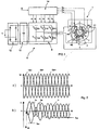
- FIG. 1 an electronically commutated, permanent magnet excited electric motor (EC motor) 1 is schematically illustrated, which has a stator 2 with three winding phases u, v, w and a permanent magnet rotor 4.
- the winding strands u, v, w are arranged in a Stem circuit, wherein in each case second winding terminals U ', V', W 'form a common Stemddling.
- the first winding terminals U, V, W are driven in a conventional manner by a commutation 6 for generating a rotor 4 driving magnetic rotating field in response to the respective rotational position of the rotor 4, so as to generate a drive torque.
- the commutation electronics 6 consists of an inverter 8 with six electronic circuit elements connected in bridge circuit (power semiconductors) T1 to T6.
- the switching elements T1 to T6 are arranged in pairs in series in three mutually parallel bridge arms and each have a parallel freewheeling diode D1 to D6.
- a first switching element T1 and a second switching element T2 in a second bridge branch, a third and fourth switching element T3, T4 and in a third bridge branch, a fifth and sixth switching element T5, T6 are arranged.
- the winding terminals U, V, W are connected to the individual bridge branches in each case between the two switching elements.
- the inverter 8 is fed from a DC intermediate circuit 10, wherein a DC voltage for the DC link 10 can be generated by an uncontrolled bridge rectifier 12 from an input AC voltage U1.
- a DC voltage for the DC link 10 can be generated by an uncontrolled bridge rectifier 12 from an input AC voltage U1.
- three Hall sensors H1, H2, H3 are placed in the engine 1, whose - in particular digital - output signals Q H1 Q H2 , Q H3 are fed to a control unit 14.
- This control unit 14, which advantageously consists of a microcontroller, determines therefrom the instantaneous rotational angle of the rotor 4 and generates control signals S1 to S6 for driving the switching elements T1 to T6 of the inverter 8 as a function of the rotor rotational position.
- the winding strands u, v, w of the motor 1 with the known commutation 6 by simultaneously turning on in each case at least two of the "upper" switching elements T1, T3, T5 or the "lower” switching elements T2, T4, T6 can be short-circuited.
- the control unit 14 needs to be designed (programmed) for a novel brake control.
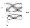
- FIG. 2 shows the courses of voltages (FIG. 2 a) and currents (FIG. 2 b) over the angle of rotation ⁇ of the rotor 4, if, in a manner not according to the invention, a three-pole short circuit is achieved by simultaneously closing all three lower or upper switching elements T1 , T3, T5 or T2, T4, T6 is performed. Immediately after this short circuit, a high transient surge short-circuit current i SK occurs, the current subsequently changing into a continuous short-circuit current i DK . The short-circuit current would lead to demagnetization of the permanent magnets in the rotor 4.
- the freewheeling diodes D1 to D6 connected in parallel must be present, which carry the current still present due to the switching off of the switching elements due to induction. If in each case two switching elements for a two-pole short circuit are closed, the associated diode can become conductive depending on the instantaneous polarity of the induced voltage at the third winding connection.
- the two-pole short circuit should therefore be carried out in this arrangement only within certain time or angle of rotation ranges. As a result of the freewheeling diodes, it could otherwise come with the two-pole short circuit to an increase in the current over the continuous short-circuit current, even if the initial surge short-circuit current is avoided.
- the angle of rotation for the two-pole short-circuit ⁇ K2 and the angle for the three-pole short-circuit ⁇ K3 are determined in this case in such a way that transient currents of high amplitude are avoided.
- Table 1 Advantageous short circuit angle to avoid overcurrents Two-pole short circuit Three-pole short circuit Shorted winding connections Conductive switching elements Offset angle ⁇ o Conductive switching elements U and V T2 and T4 150 ° el T2, T4 and T6 T1 and T3 330 ° el T1, T3 and T5 V and W T4 and T6 270 ° el T2, T4 and T6 T3 and T5 90 ° el T1, T3 and T5 U and W T2 and T6 30 ° el T2, T4 and T6 T1 and T5 210 ° el T1, T3 and T5
- the optimum values for avoiding a transient current increase can also be determined empirically if the motor parameters R and L are not known exactly or if additional motor-dependent influences, such. As saturation of the iron or anchor reaction, must be considered.
- the specified calculation forms are therefore to be understood as examples only.
- the inventive method can be realized with the control unit 14, for example by simply extending the software of a microcontroller already available for commutation at no extra cost.
- the microcontroller can use the rotor rotational position signals Q H1 , Q H2 , Q H3 to determine the instantaneous rotational angle ⁇ and the instantaneous rotational frequency ⁇ .
- the predetermined short circuit angle ⁇ K2 and ⁇ K3 and the associated short-circuit rotational frequency ⁇ K are deposited. If z. B. via a control signal input E of the electronics given a motor stop command, then the microcontroller interrupts the winding currents and compares the instantaneous rotational frequency ⁇ with the stored associated short-circuit rotational frequency ⁇ K.
- the instantaneous rotation angle ⁇ is compared with the stored short-circuit angles ⁇ K2 and ⁇ K3 , and upon exceeding or reaching the corresponding switching elements for short-circuiting of the windings are switched on statically.
- the motor data L and R can be stored in the microcontroller.
- the energization of the motor 1 is again interrupted, and immediately according to the instantaneous rotational frequency ⁇ and the instantaneous rotational angle ⁇ according to the above table the nearest short circuit angle ⁇ K2 and ⁇ K3 calculated.
- the associated switching elements are closed. As a result, the fastest possible stopping of the engine can be achieved at each engine speed.
- the inventive method allows braking almost at an arbitrarily high speed, without jeopardizing the permanent magnets of the rotor. Furthermore, a very uniform braking torque is generated by the immediate transition from the two-pole to a three-pole short circuit, which allows a smooth and quiet braking of the engine. No extra effort (hardware) is required to perform the procedure. Rather, the method can be implemented with the commutation electronics required for normal commutation and designed for operation in the first or third quadrant. The switching elements of the inverter need not be clocked, but are static switched on for short circuit, so that the occurring short-circuit currents do not lead to increasing compared to the normal operation at rated load heating. As a result, no special dimensioning (oversizing) is required.
- the invention is not limited to the illustrated and described example.
- another programmable device for example CPLD or FGPA, or a conventional analog or digital circuit may be used for the control unit 14 instead of a microcontroller.
- the invention is not limited to the described two-pole example of a motor Stemscnies, but is equally suitable for motors in delta connection or motors with higher numbers of poles.
Landscapes
- Engineering & Computer Science (AREA)
- Power Engineering (AREA)
- Control Of Motors That Do Not Use Commutators (AREA)
- Control Of Ac Motors In General (AREA)
- Moulds For Moulding Plastics Or The Like (AREA)
- Control Of Positive-Displacement Air Blowers (AREA)
- Permanent Magnet Type Synchronous Machine (AREA)
- Stopping Of Electric Motors (AREA)
Priority Applications (5)
| Application Number | Priority Date | Filing Date | Title |
|---|---|---|---|
| ES03025988T ES2261850T3 (es) | 2003-11-14 | 2003-11-14 | Procedimiento para la reduccion del tiempo de marcha por inercia de un motor electrico. |
| DE50303124T DE50303124D1 (de) | 2003-11-14 | 2003-11-14 | Verfahren zum Reduzieren der Auslaufzeit eines Elektromotors |
| PT03025988T PT1533892E (pt) | 2003-11-14 | 2003-11-14 | Metodo para produzir o tempo de paragem de um motor electrico. |
| EP03025988A EP1533892B9 (de) | 2003-11-14 | 2003-11-14 | Verfahren zum Reduzieren der Auslaufzeit eines Elektromotors |
| AT03025988T ATE324700T1 (de) | 2003-11-14 | 2003-11-14 | Verfahren zum reduzieren der auslaufzeit eines elektromotors |
Applications Claiming Priority (1)
| Application Number | Priority Date | Filing Date | Title |
|---|---|---|---|
| EP03025988A EP1533892B9 (de) | 2003-11-14 | 2003-11-14 | Verfahren zum Reduzieren der Auslaufzeit eines Elektromotors |
Publications (3)
| Publication Number | Publication Date |
|---|---|
| EP1533892A1 EP1533892A1 (de) | 2005-05-25 |
| EP1533892B1 EP1533892B1 (de) | 2006-04-26 |
| EP1533892B9 true EP1533892B9 (de) | 2006-07-05 |
Family
ID=34429347
Family Applications (1)
| Application Number | Title | Priority Date | Filing Date |
|---|---|---|---|
| EP03025988A Expired - Lifetime EP1533892B9 (de) | 2003-11-14 | 2003-11-14 | Verfahren zum Reduzieren der Auslaufzeit eines Elektromotors |
Country Status (5)
| Country | Link |
|---|---|
| EP (1) | EP1533892B9 (es) |
| AT (1) | ATE324700T1 (es) |
| DE (1) | DE50303124D1 (es) |
| ES (1) | ES2261850T3 (es) |
| PT (1) | PT1533892E (es) |
Families Citing this family (5)
| Publication number | Priority date | Publication date | Assignee | Title |
|---|---|---|---|---|
| FR2918222B1 (fr) * | 2007-06-27 | 2010-06-04 | Valeo Equip Electr Moteur | Procede et une machine electrique de freinage d'un moteur thermique et vehicule lors de la phase d'arret de celui-ci. |
| DE102011006037A1 (de) * | 2011-03-24 | 2012-09-27 | Robert Bosch Gmbh | Verfahren zum Betreiben einer von einem Verbrennungsmotor angetriebenen elektrischen Maschine in einem Kraftfahrzeug |
| DE102013213045A1 (de) * | 2013-07-04 | 2015-01-08 | Voith Patent Gmbh | Vermeidung von Bremsmomenten bei permanenterregten Synchronmaschinen |
| DE102017212303A1 (de) * | 2017-07-18 | 2019-01-24 | Bayerische Motoren Werke Aktiengesellschaft | Vorrichtung zum Absichern einer elektrischen Maschine |
| EP4733119A1 (en) * | 2024-10-23 | 2026-04-29 | C.R.F. Società Consortile per Azioni | Control strategy of electric motors of electric traction systems |
Family Cites Families (4)
| Publication number | Priority date | Publication date | Assignee | Title |
|---|---|---|---|---|
| JP2536010B2 (ja) * | 1988-01-25 | 1996-09-18 | ティアツク株式会社 | 3相ブラシレスモ―タ装置 |
| JP3315792B2 (ja) * | 1993-12-24 | 2002-08-19 | 株式会社ミツバ | ブラシレスモータの制御回路 |
| US5914582A (en) * | 1997-01-27 | 1999-06-22 | Hitachi, Ltd. | Permanent magnet synchronous motor controller and electric vehicle controller |
| US6118241A (en) * | 1997-11-25 | 2000-09-12 | Kollmorgen Corporation | Dynamic braking system for electric motors |
-
2003
- 2003-11-14 PT PT03025988T patent/PT1533892E/pt unknown
- 2003-11-14 DE DE50303124T patent/DE50303124D1/de not_active Expired - Lifetime
- 2003-11-14 AT AT03025988T patent/ATE324700T1/de not_active IP Right Cessation
- 2003-11-14 EP EP03025988A patent/EP1533892B9/de not_active Expired - Lifetime
- 2003-11-14 ES ES03025988T patent/ES2261850T3/es not_active Expired - Lifetime
Also Published As
| Publication number | Publication date |
|---|---|
| EP1533892B1 (de) | 2006-04-26 |
| DE50303124D1 (de) | 2006-06-01 |
| EP1533892A1 (de) | 2005-05-25 |
| ATE324700T1 (de) | 2006-05-15 |
| ES2261850T3 (es) | 2006-11-16 |
| PT1533892E (pt) | 2006-06-30 |
Similar Documents
| Publication | Publication Date | Title |
|---|---|---|
| DE69727651T2 (de) | Vorrichtung zur Steuerung eines Synchronomotors mit einem Dauermagnetläufer | |
| DE69723913T2 (de) | System und Verfahren zum Schutz eines Einphasenmotors vor Freilaufströmen | |
| EP0989666B1 (de) | System zur Drehzahlsteuerung von Wechselstrom-Motoren | |
| DE60023317T2 (de) | Ansteuerung einer elektrischen reluktanzmaschine | |
| EP2529480A2 (de) | Verfahren zur verbesserung des wirkungsgrades bei einem mehrphasigen motor, und motor zur durchführung eines solchen verfahrens | |
| EP1499008A2 (de) | Verfahren und Steuersystem zur elektronischen Kommutierung eines bürstenlosen Gleichstrommotors | |
| EP3391492B1 (de) | Leistungselektronikeinheit | |
| EP4372977A1 (de) | Antriebssystem | |
| EP1533892B9 (de) | Verfahren zum Reduzieren der Auslaufzeit eines Elektromotors | |
| DE102017115740B4 (de) | System einer rotierenden elektrische Maschine | |
| DE10332228B4 (de) | Steuerungsverfahren für einen bürstenlosen Elektromotor, insbesonde Lüftermotor | |
| EP2104221A1 (de) | Verfahren zum Ansteuern eines mehrphasigen in Sternschaltung betriebenen Elektromotors | |
| WO2008064791A2 (de) | Elektrische antriebsvorrichtung | |
| EP0903007B1 (de) | Anordnung mit einem elektronisch kommutierten motor | |
| BE1030973B1 (de) | Antriebssystem | |
| DE10127670A1 (de) | Bürstenloser dreiphasiger Elektromotor und Verfahren zu dessen Ansteuerung | |
| DE4413802C2 (de) | Verfahren und Vorrichtung zum Steuern der Drehzahl eines elektrischen Dreiphasen-Asynchronmotors | |
| WO2002003538A1 (de) | Verfahren zum betrieb eines bürstenlosen gleichstrommotors | |
| DE10163886A1 (de) | Verfahren zur elektronischen Kommutierung eines bürstenlosen Gleichstrommotors | |
| EP3676951B1 (de) | Ansteuerung eines lüftermotors für ein verbessertes emv-verhalten | |
| WO2003028203A1 (de) | Kaskade mit elektronischer abschaltung und erweitertem drehzahlbereich | |
| DE102023203930A1 (de) | Verfahren zur Steuerung eines bürstenlosen Elektromotors und Vorrichtung zur Durchführung des Verfahrens | |
| EP4593281A1 (de) | Antriebssystem | |
| DE102021209723A1 (de) | Verfahren zum Betrieb einer elektrischen Maschine | |
| DE102010053383B4 (de) | Kommutierungsverfahren für einen bürstenlosen Gleichstrommotor |
Legal Events
| Date | Code | Title | Description |
|---|---|---|---|
| PUAI | Public reference made under article 153(3) epc to a published international application that has entered the european phase |
Free format text: ORIGINAL CODE: 0009012 |
|
| 17P | Request for examination filed |
Effective date: 20040914 |
|
| AK | Designated contracting states |
Kind code of ref document: A1 Designated state(s): AT BE BG CH CY CZ DE DK EE ES FI FR GB GR HU IE IT LI LU MC NL PT RO SE SI SK TR |
|
| AX | Request for extension of the european patent |
Extension state: AL LT LV MK |
|
| GRAP | Despatch of communication of intention to grant a patent |
Free format text: ORIGINAL CODE: EPIDOSNIGR1 |
|
| AKX | Designation fees paid |
Designated state(s): AT BE BG CH CY CZ DE DK EE ES FI FR GB GR HU IE IT LI LU MC NL PT RO SE SI SK TR |
|
| GRAS | Grant fee paid |
Free format text: ORIGINAL CODE: EPIDOSNIGR3 |
|
| GRAA | (expected) grant |
Free format text: ORIGINAL CODE: 0009210 |
|
| AK | Designated contracting states |
Kind code of ref document: B1 Designated state(s): AT BE BG CH CY CZ DE DK EE ES FI FR GB GR HU IE IT LI LU MC NL PT RO SE SI SK TR |
|
| PG25 | Lapsed in a contracting state [announced via postgrant information from national office to epo] |
Ref country code: IT Free format text: LAPSE BECAUSE OF FAILURE TO SUBMIT A TRANSLATION OF THE DESCRIPTION OR TO PAY THE FEE WITHIN THE PRESCRIBED TIME-LIMIT;WARNING: LAPSES OF ITALIAN PATENTS WITH EFFECTIVE DATE BEFORE 2007 MAY HAVE OCCURRED AT ANY TIME BEFORE 2007. THE CORRECT EFFECTIVE DATE MAY BE DIFFERENT FROM THE ONE RECORDED. Effective date: 20060426 Ref country code: FI Free format text: LAPSE BECAUSE OF FAILURE TO SUBMIT A TRANSLATION OF THE DESCRIPTION OR TO PAY THE FEE WITHIN THE PRESCRIBED TIME-LIMIT Effective date: 20060426 Ref country code: IE Free format text: LAPSE BECAUSE OF FAILURE TO SUBMIT A TRANSLATION OF THE DESCRIPTION OR TO PAY THE FEE WITHIN THE PRESCRIBED TIME-LIMIT Effective date: 20060426 Ref country code: SI Free format text: LAPSE BECAUSE OF FAILURE TO SUBMIT A TRANSLATION OF THE DESCRIPTION OR TO PAY THE FEE WITHIN THE PRESCRIBED TIME-LIMIT Effective date: 20060426 Ref country code: SK Free format text: LAPSE BECAUSE OF FAILURE TO SUBMIT A TRANSLATION OF THE DESCRIPTION OR TO PAY THE FEE WITHIN THE PRESCRIBED TIME-LIMIT Effective date: 20060426 Ref country code: RO Free format text: LAPSE BECAUSE OF FAILURE TO SUBMIT A TRANSLATION OF THE DESCRIPTION OR TO PAY THE FEE WITHIN THE PRESCRIBED TIME-LIMIT Effective date: 20060426 Ref country code: CZ Free format text: LAPSE BECAUSE OF FAILURE TO SUBMIT A TRANSLATION OF THE DESCRIPTION OR TO PAY THE FEE WITHIN THE PRESCRIBED TIME-LIMIT Effective date: 20060426 |
|
| REG | Reference to a national code |
Ref country code: GB Ref legal event code: FG4D Free format text: NOT ENGLISH |
|
| REG | Reference to a national code |
Ref country code: IE Ref legal event code: FG4D Free format text: LANGUAGE OF EP DOCUMENT: GERMAN |
|
| REF | Corresponds to: |
Ref document number: 50303124 Country of ref document: DE Date of ref document: 20060601 Kind code of ref document: P |
|
| REG | Reference to a national code |
Ref country code: SE Ref legal event code: TRGR |
|
| REG | Reference to a national code |
Ref country code: PT Ref legal event code: SC4A Effective date: 20060428 |
|
| PG25 | Lapsed in a contracting state [announced via postgrant information from national office to epo] |
Ref country code: DK Free format text: LAPSE BECAUSE OF FAILURE TO SUBMIT A TRANSLATION OF THE DESCRIPTION OR TO PAY THE FEE WITHIN THE PRESCRIBED TIME-LIMIT Effective date: 20060726 |
|
| GBT | Gb: translation of ep patent filed (gb section 77(6)(a)/1977) |
Effective date: 20060802 |
|
| REG | Reference to a national code |
Ref country code: SE Ref legal event code: RPOT |
|
| ET | Fr: translation filed | ||
| REG | Reference to a national code |
Ref country code: IE Ref legal event code: FD4D |
|
| REG | Reference to a national code |
Ref country code: ES Ref legal event code: FG2A Ref document number: 2261850 Country of ref document: ES Kind code of ref document: T3 |
|
| PG25 | Lapsed in a contracting state [announced via postgrant information from national office to epo] |
Ref country code: BE Free format text: LAPSE BECAUSE OF NON-PAYMENT OF DUE FEES Effective date: 20061130 Ref country code: MC Free format text: LAPSE BECAUSE OF NON-PAYMENT OF DUE FEES Effective date: 20061130 |
|
| NLR4 | Nl: receipt of corrected translation in the netherlands language at the initiative of the proprietor of the patent | ||
| PLBE | No opposition filed within time limit |
Free format text: ORIGINAL CODE: 0009261 |
|
| STAA | Information on the status of an ep patent application or granted ep patent |
Free format text: STATUS: NO OPPOSITION FILED WITHIN TIME LIMIT |
|
| 26N | No opposition filed |
Effective date: 20070129 |
|
| BERE | Be: lapsed |
Owner name: EBM-PAPST MULFINGEN G.M.B.H. & CO.KG Effective date: 20061130 |
|
| PG25 | Lapsed in a contracting state [announced via postgrant information from national office to epo] |
Ref country code: AT Free format text: LAPSE BECAUSE OF NON-PAYMENT OF DUE FEES Effective date: 20061114 |
|
| PG25 | Lapsed in a contracting state [announced via postgrant information from national office to epo] |
Ref country code: GR Free format text: LAPSE BECAUSE OF FAILURE TO SUBMIT A TRANSLATION OF THE DESCRIPTION OR TO PAY THE FEE WITHIN THE PRESCRIBED TIME-LIMIT Effective date: 20060727 |
|
| PG25 | Lapsed in a contracting state [announced via postgrant information from national office to epo] |
Ref country code: BG Free format text: LAPSE BECAUSE OF FAILURE TO SUBMIT A TRANSLATION OF THE DESCRIPTION OR TO PAY THE FEE WITHIN THE PRESCRIBED TIME-LIMIT Effective date: 20060726 Ref country code: EE Free format text: LAPSE BECAUSE OF FAILURE TO SUBMIT A TRANSLATION OF THE DESCRIPTION OR TO PAY THE FEE WITHIN THE PRESCRIBED TIME-LIMIT Effective date: 20060426 |
|
| PG25 | Lapsed in a contracting state [announced via postgrant information from national office to epo] |
Ref country code: TR Free format text: LAPSE BECAUSE OF FAILURE TO SUBMIT A TRANSLATION OF THE DESCRIPTION OR TO PAY THE FEE WITHIN THE PRESCRIBED TIME-LIMIT Effective date: 20060426 Ref country code: CH Free format text: LAPSE BECAUSE OF NON-PAYMENT OF DUE FEES Effective date: 20071130 Ref country code: LI Free format text: LAPSE BECAUSE OF NON-PAYMENT OF DUE FEES Effective date: 20071130 Ref country code: LU Free format text: LAPSE BECAUSE OF NON-PAYMENT OF DUE FEES Effective date: 20061114 Ref country code: HU Free format text: LAPSE BECAUSE OF FAILURE TO SUBMIT A TRANSLATION OF THE DESCRIPTION OR TO PAY THE FEE WITHIN THE PRESCRIBED TIME-LIMIT Effective date: 20061027 |
|
| REG | Reference to a national code |
Ref country code: CH Ref legal event code: PL |
|
| PG25 | Lapsed in a contracting state [announced via postgrant information from national office to epo] |
Ref country code: CY Free format text: LAPSE BECAUSE OF FAILURE TO SUBMIT A TRANSLATION OF THE DESCRIPTION OR TO PAY THE FEE WITHIN THE PRESCRIBED TIME-LIMIT Effective date: 20060426 |
|
| REG | Reference to a national code |
Ref country code: FR Ref legal event code: PLFP Year of fee payment: 13 |
|
| REG | Reference to a national code |
Ref country code: FR Ref legal event code: PLFP Year of fee payment: 14 |
|
| REG | Reference to a national code |
Ref country code: FR Ref legal event code: PLFP Year of fee payment: 15 |
|
| REG | Reference to a national code |
Ref country code: DE Ref legal event code: R082 Ref document number: 50303124 Country of ref document: DE Representative=s name: PATENTANWAELTE STAEGER & SPERLING PARTNERSCHAF, DE |
|
| PGFP | Annual fee paid to national office [announced via postgrant information from national office to epo] |
Ref country code: SE Payment date: 20221122 Year of fee payment: 20 Ref country code: PT Payment date: 20221031 Year of fee payment: 20 Ref country code: NL Payment date: 20221118 Year of fee payment: 20 Ref country code: IT Payment date: 20221130 Year of fee payment: 20 Ref country code: GB Payment date: 20221123 Year of fee payment: 20 Ref country code: FR Payment date: 20221118 Year of fee payment: 20 Ref country code: ES Payment date: 20221216 Year of fee payment: 20 Ref country code: DE Payment date: 20221121 Year of fee payment: 20 |
|
| REG | Reference to a national code |
Ref country code: DE Ref legal event code: R071 Ref document number: 50303124 Country of ref document: DE |
|
| REG | Reference to a national code |
Ref country code: NL Ref legal event code: MK Effective date: 20231113 |
|
| REG | Reference to a national code |
Ref country code: ES Ref legal event code: FD2A Effective date: 20231128 |
|
| REG | Reference to a national code |
Ref country code: GB Ref legal event code: PE20 Expiry date: 20231113 |
|
| REG | Reference to a national code |
Ref country code: SE Ref legal event code: EUG |
|
| PG25 | Lapsed in a contracting state [announced via postgrant information from national office to epo] |
Ref country code: GB Free format text: LAPSE BECAUSE OF EXPIRATION OF PROTECTION Effective date: 20231113 |
|
| PG25 | Lapsed in a contracting state [announced via postgrant information from national office to epo] |
Ref country code: ES Free format text: LAPSE BECAUSE OF EXPIRATION OF PROTECTION Effective date: 20231115 |
|
| PG25 | Lapsed in a contracting state [announced via postgrant information from national office to epo] |
Ref country code: PT Free format text: LAPSE BECAUSE OF EXPIRATION OF PROTECTION Effective date: 20231123 Ref country code: GB Free format text: LAPSE BECAUSE OF EXPIRATION OF PROTECTION Effective date: 20231113 Ref country code: ES Free format text: LAPSE BECAUSE OF EXPIRATION OF PROTECTION Effective date: 20231115 |