EP1533835A1 - Verdampfer, verschiedene, diesen enthaltende vorrichtungen und verdampfungsverfahren - Google Patents
Verdampfer, verschiedene, diesen enthaltende vorrichtungen und verdampfungsverfahren Download PDFInfo
- Publication number
- EP1533835A1 EP1533835A1 EP03733161A EP03733161A EP1533835A1 EP 1533835 A1 EP1533835 A1 EP 1533835A1 EP 03733161 A EP03733161 A EP 03733161A EP 03733161 A EP03733161 A EP 03733161A EP 1533835 A1 EP1533835 A1 EP 1533835A1
- Authority
- EP
- European Patent Office
- Prior art keywords
- gas
- raw material
- vaporizer
- material solution
- section
- Prior art date
- Legal status (The legal status is an assumption and is not a legal conclusion. Google has not performed a legal analysis and makes no representation as to the accuracy of the status listed.)
- Withdrawn
Links
Images









Classifications
-
- C—CHEMISTRY; METALLURGY
- C23—COATING METALLIC MATERIAL; COATING MATERIAL WITH METALLIC MATERIAL; CHEMICAL SURFACE TREATMENT; DIFFUSION TREATMENT OF METALLIC MATERIAL; COATING BY VACUUM EVAPORATION, BY SPUTTERING, BY ION IMPLANTATION OR BY CHEMICAL VAPOUR DEPOSITION, IN GENERAL; INHIBITING CORROSION OF METALLIC MATERIAL OR INCRUSTATION IN GENERAL
- C23C—COATING METALLIC MATERIAL; COATING MATERIAL WITH METALLIC MATERIAL; SURFACE TREATMENT OF METALLIC MATERIAL BY DIFFUSION INTO THE SURFACE, BY CHEMICAL CONVERSION OR SUBSTITUTION; COATING BY VACUUM EVAPORATION, BY SPUTTERING, BY ION IMPLANTATION OR BY CHEMICAL VAPOUR DEPOSITION, IN GENERAL
- C23C16/00—Chemical coating by decomposition of gaseous compounds, without leaving reaction products of surface material in the coating, i.e. chemical vapour deposition [CVD] processes
- C23C16/22—Chemical coating by decomposition of gaseous compounds, without leaving reaction products of surface material in the coating, i.e. chemical vapour deposition [CVD] processes characterised by the deposition of inorganic material, other than metallic material
- C23C16/30—Deposition of compounds, mixtures or solid solutions, e.g. borides, carbides, nitrides
- C23C16/40—Oxides
-
- C—CHEMISTRY; METALLURGY
- C23—COATING METALLIC MATERIAL; COATING MATERIAL WITH METALLIC MATERIAL; CHEMICAL SURFACE TREATMENT; DIFFUSION TREATMENT OF METALLIC MATERIAL; COATING BY VACUUM EVAPORATION, BY SPUTTERING, BY ION IMPLANTATION OR BY CHEMICAL VAPOUR DEPOSITION, IN GENERAL; INHIBITING CORROSION OF METALLIC MATERIAL OR INCRUSTATION IN GENERAL
- C23C—COATING METALLIC MATERIAL; COATING MATERIAL WITH METALLIC MATERIAL; SURFACE TREATMENT OF METALLIC MATERIAL BY DIFFUSION INTO THE SURFACE, BY CHEMICAL CONVERSION OR SUBSTITUTION; COATING BY VACUUM EVAPORATION, BY SPUTTERING, BY ION IMPLANTATION OR BY CHEMICAL VAPOUR DEPOSITION, IN GENERAL
- C23C16/00—Chemical coating by decomposition of gaseous compounds, without leaving reaction products of surface material in the coating, i.e. chemical vapour deposition [CVD] processes
- C23C16/44—Chemical coating by decomposition of gaseous compounds, without leaving reaction products of surface material in the coating, i.e. chemical vapour deposition [CVD] processes characterised by the method of coating
- C23C16/448—Chemical coating by decomposition of gaseous compounds, without leaving reaction products of surface material in the coating, i.e. chemical vapour deposition [CVD] processes characterised by the method of coating characterised by the method used for generating reactive gas streams, e.g. by evaporation or sublimation of precursor materials
- C23C16/4481—Chemical coating by decomposition of gaseous compounds, without leaving reaction products of surface material in the coating, i.e. chemical vapour deposition [CVD] processes characterised by the method of coating characterised by the method used for generating reactive gas streams, e.g. by evaporation or sublimation of precursor materials by evaporation using carrier gas in contact with the source material
-
- C—CHEMISTRY; METALLURGY
- C23—COATING METALLIC MATERIAL; COATING MATERIAL WITH METALLIC MATERIAL; CHEMICAL SURFACE TREATMENT; DIFFUSION TREATMENT OF METALLIC MATERIAL; COATING BY VACUUM EVAPORATION, BY SPUTTERING, BY ION IMPLANTATION OR BY CHEMICAL VAPOUR DEPOSITION, IN GENERAL; INHIBITING CORROSION OF METALLIC MATERIAL OR INCRUSTATION IN GENERAL
- C23C—COATING METALLIC MATERIAL; COATING MATERIAL WITH METALLIC MATERIAL; SURFACE TREATMENT OF METALLIC MATERIAL BY DIFFUSION INTO THE SURFACE, BY CHEMICAL CONVERSION OR SUBSTITUTION; COATING BY VACUUM EVAPORATION, BY SPUTTERING, BY ION IMPLANTATION OR BY CHEMICAL VAPOUR DEPOSITION, IN GENERAL
- C23C16/00—Chemical coating by decomposition of gaseous compounds, without leaving reaction products of surface material in the coating, i.e. chemical vapour deposition [CVD] processes
- C23C16/44—Chemical coating by decomposition of gaseous compounds, without leaving reaction products of surface material in the coating, i.e. chemical vapour deposition [CVD] processes characterised by the method of coating
- C23C16/448—Chemical coating by decomposition of gaseous compounds, without leaving reaction products of surface material in the coating, i.e. chemical vapour deposition [CVD] processes characterised by the method of coating characterised by the method used for generating reactive gas streams, e.g. by evaporation or sublimation of precursor materials
- C23C16/4486—Chemical coating by decomposition of gaseous compounds, without leaving reaction products of surface material in the coating, i.e. chemical vapour deposition [CVD] processes characterised by the method of coating characterised by the method used for generating reactive gas streams, e.g. by evaporation or sublimation of precursor materials by producing an aerosol and subsequent evaporation of the droplets or particles
-
- H—ELECTRICITY
- H10—SEMICONDUCTOR DEVICES; ELECTRIC SOLID-STATE DEVICES NOT OTHERWISE PROVIDED FOR
- H10P—GENERIC PROCESSES OR APPARATUS FOR THE MANUFACTURE OR TREATMENT OF DEVICES COVERED BY CLASS H10
- H10P72/00—Handling or holding of wafers, substrates or devices during manufacture or treatment thereof
- H10P72/04—Apparatus for manufacture or treatment
- H10P72/0402—Apparatus for fluid treatment
- H10P72/0418—Apparatus for fluid treatment for etching
- H10P72/0422—Apparatus for fluid treatment for etching for wet etching
- H10P72/0424—Apparatus for fluid treatment for etching for wet etching using mainly spraying means, e.g. nozzles
Definitions
- the present invention relates to a vaporizer suitably used for a film forming apparatus such as a MOCVD film forming apparatus and a vaporizing method, and a film forming apparatus and other various types of apparatuses.
- a problem arising in the development of DRAM is a decrease in storage capacitance caused by miniaturization. From the viewpoint of software error, capacitance of the same level as that of the old generation is required, so that it is necessary to take some measures.
- the measures although the cell structure up to 1M has been a planar structure, from 4M, a three-dimensional structure called a stack structure or a trench structure has been adopted to increase the capacitor area.
- the dielectric film which has conventionally been a thermally-oxidized film of substrate Si, a film formed by laminating a thermally-oxidized film and a CVD nitrided film on poly Si (this laminated film is generally called an ON film) has been adopted.
- the stack type in order to further increase the area contributing to the capacitance, for the stack type, a three-dimensional type using the side surface, a fin type in which the back surface of plate is also used, and the like type have been used.
- Bi-based laminar structure having a crystalline structure highly similar to that of a superconductive material has recently received great attention because it has a large dielectric constant and self polarization of ferroelectric characteristic, and hence it is superior as a nonvolatile memory.
- SrBi 2 TaO 9 ferroelectric thin film is formed by the MOCVD (metal organic chemical vapor deposition) method which is practical and promising.
- SrBi 2 TaO 9 ferroelectric thin film is formed by the MOCVD (metal organic chemical vapor deposition) method which is practical and promising.
- the raw materials for the ferroelectric thin film are, for example, three kinds of organic metal complexes of Sr(DPM) 2 , Bi(C 6 H 5 ) 3 , and Ta(OC 2 H 5 ) 5 . Each of these materials is used as a raw material solution by being dissolved in THF (tetrahydrofuran), hexane, or other solvents. Sr(Ta(OEt)6) 2 and BI(OtAm) 3 are also used as a raw material solution by being dissolved in hexane or other solvents. DPM is the abbreviation of dipivaloylmethane.
- An apparatus used for the MOCVD method includes a reaction section in which the SrBi 2 TaO 9 thin film raw material undergoes gas phase reaction and surface reaction to form a film and a supply section in which the SrBi 2 TaO 9 thin film raw material and an oxidizing agent are supplied to the reaction section.
- the supply section is provided with a vaporizer for vaporizing the thin film raw material.
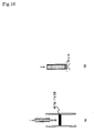
- the method shown in Figure 16(a) which is called a metal filter method, is a method in which vaporization is accomplished by introducing a raw material solution heated to a predetermined temperature to a metal filter used for increasing the contact area of gas existing in the surroundings with the SrBi 2 TaO 9 ferroelectric thin film raw material solution.
- the metal filter is clogged by vaporization for several hours, which poses a problem in that this metal filter cannot be used for a long period of time.
- the inventor presumed that the reason for this is that the solution is heated and a substance having a lower vaporization temperature evaporates.
- Figure 16(b) shows a technique in which a raw material solution is discharged through a minute hole of 10 ⁇ m by applying a pressure of 30 kgf/cm 2 to the raw material solution, by which the raw material solution is vaporized by expansion.
- the raw material solution is a mixed solution of a plurality of organic metal complexes
- a mixed solution of Sr(DPM) 2 /THF and Bi(C 6 H 5 ) 3 /THF and (OC 2 H 5 ) 5 /THF a mixed solution of Sr(DPM) 2 /THF and Bi(C 6 H 5 ) 3 /THF and (OC 2 H 5 ) 5 /THF
- a solvent having the highest vapor pressure in this case, THF
- the quantity of heat capable of evaporating or changing the solvent is added in a liquid or mist state.
- a vaporizer for MOCVD including:
- This technique provides a vaporizer for MOCVD that is clogged far less than the conventional example so that it can be used for a long period of time, and can supply a raw material stably to the reaction section.
- an introduction port of oxygen heated beforehand is provided on the downstream side of the vaporization section.
- a large quantity of carbon (30 to 40 at%) is contained in the formed film.
- annealing for example, 800°C, 60 minutes, oxygen atmosphere
- annealing must be performed at a high temperature after film formation.
- An object of the present invention is to provide a vaporizer which can be used for a long period of time without the occurrence of clogging etc, and can supply a raw material stably to the reaction section.
- Another object of the present invention is to provide a vaporizer in which the content of carbon in a film can be made very low even in an as-deposited state and the percentage composition of film can be controlled exactly, a film forming apparatus and other various types of apparatuses, and a vaporizing method.
- Still another object of the present invention is to provide a vaporizer and a vaporizing method in which a vaporized gas in which a raw material solution is dispersed homogeneously can be obtained.
- Still another object of the present invention is to provide a vaporizer which can supply a raw material adjusted to a stoichiometric ratio continuously and stably and has an effect of decreasing the quantity of residual carbon in a formed film, a disperser, a film forming apparatus, and a vaporizing method, and a dispersing method and a film forming method.
- the present invention adds the following operation to enhance the performance of a vaporizer used for MOCVD etc. and to stabilize vaporization.
- an inert gas or an inert gas containing a predetermined amount of oxygen is supplied to a narrow flow path of the vaporizer cooled to a temperature close to room temperature, a high-velocity air flow is produced, and a raw material is supplied to the air flow at a predetermined rate, by which the raw material is made in a mist form.
- the flow rate of the supplied inert gas or inert gas containing a predetermined amount of oxygen is higher than the quantity of supplied raw material, so that it is conjectured that a solvent for dissolving or dispersing the raw material is scattered in a gas phase by mass transfer. Therefore, the raw material for organic metal compound accumulates in a paste form in the flow path, which may be a cause for the instability in making the raw material in a mist form and the clogging of flow path.
- the air flow of inert gas or inert gas containing a predetermined amount of oxygen is beforehand made in a saturated state by the solvent used for the raw material, and then is supplied to the vaporizer.
- the object can be attained by bubbling the air flow of inert gas or inert gas containing a predetermined amount of oxygen in a container which contains the solvent and is kept at a predetermined temperature.
- the solvent of a quantity enough to saturate the air flow of solvent used for the raw material by means of the vapor of solvent has only to be supplied to a position just in front of the vaporizer of a raw material line supplied to the vaporizer.
- the quantity of supplied solvent is determined by the following simple formula by knowing the molecular weight and density of solvent, the pressure of air flow, the flow rate of air flow in a standard state, and the like under the data of the saturated vapor corresponding the temperature of vaporizer.
- M H,C is the molecular weight of solvent (H,C) [g/mol]
- P H,C is the density of solvent (H,C) [g/cm 3 ]
- P t is the total pressure of mixed gas in the vaporizer flow path [Torr]
- V 00.25 is the flow rate of argon gas at 25°C, 1 cm [1/min]
- V 02.25
- the vaporizer in accordance with the present invention is a vaporizer for vaporizing a raw material solution contained in a gas carrier, characterized in that means for containing a solvent for the raw material solution in the carrier gas before containing the raw material solution is provided.
- the disperser in accordance with the present invention is a disperser for containing a raw material in a carrier gas, characterized in that means for containing a solvent of the raw material solution in the carrier gas before containing the raw material solution is provided.
- the vaporizing method in accordance with the present invention is a vaporizing method for vaporizing a raw material solution contained in a carrier gas, characterized in that a solvent for the raw material solution is contained in the carrier gas before containing the raw material solution.
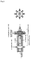
- Figure 1 shows a vaporizer for MOCVD in accordance with example 1.
- the vaporizer includes:
- the interior of the dispersion section body 1 is a cylindrical hollow portion.
- a rod 10 is inserted in the hollow portion, and the gas passage 2 is formed by the internal wall of the dispersion section body and the rod 10.
- the hollow portion is not limited to the cylindrical shape, and may take any other shapes.
- a conical shape is preferable.
- the conical angle of the conical hollow portion is preferably 0 to 45°, more preferably 8 to 20°. The same is true in other examples.
- the cross sectional area of the gas passage is preferably 0.10 to 0.5 mm 2 . If it is less than 0.10 mm 2 , the fabrication is difficult to do. If it exceeds 0.5 mm 2 , it is necessary to use a high-pressure carrier gas with a high flow rate to speed up the carrier gas.
- a high-capacity large vacuum pump is needed to keep a reaction chamber in a depressurized state (for example, 1.0 Torr). Since it is difficult to use a vacuum pump having an evacuation capacity exceeding 10,000 liters/min (at 1.0 Torr), in order to achieve industrially practical application, a proper flow rate, i.e., a gas passage area of 0.10 to 0.5 mm 2 is preferable.
- the gas introduction port 4 is provided.
- the gas introduction port 4 is connected with a carrier gas (for example, N 2 , Ar, He) source (not shown).
- a carrier gas for example, N 2 , Ar, He
- the raw material supply port 6 is provided so as to communicate with the gas passage 2, so that the raw material solution 5 is introduced into the gas passage 2, and thus the raw material solution 5 can be dispersed in the carrier gas passing through the gas passage 2 to form the raw material gas.
- the gas outlet 7 communicating with the vaporization tube 20 of the vaporization section 22 is provided.
- a space 11 for causing the cooling water 18 to flow is formed in the dispersion section body 1.
- the carrier gas flowing in the gas passage 2 is cooled.
- a Peltier element etc. may be provided to cool the carrier gas. Since the interior of the gas passage 2 of the dispersion section 8 is thermally affected by the heater 21 of the vaporization section 22, a solvent and an organic metal complex of the raw material solution do not vaporize at the same time in the gas passage 2, and only the solvent vaporizes. Therefore, by cooling the carrier gas in which the raw material solution is dispersed, flowing in the gas passage 2, vaporization of only the solvent is prevented.
- the cooling on the downstream side of the raw material supply hole 6 is important, and therefore at least a portion on the downstream side of the raw material supply hole 6 is cooled.
- the cooling temperature is a temperature equal to or lower than the boiling point of solvent.
- the cooling temperature is 67°C or lower.
- the temperature at the gas outlet 7 is important.
- the heat in the vaporization section overheats the gas in the gas passage 2 via the gas outlet 7 as radiation heat. Therefore, even if the gas is cooled by the cooling water 18, a low melting point component in the gas deposits near the gas outlet 7.
- the radiation preventive portion is a member for preventing the radiation heat from propagating to the gas. Therefore, the cross-sectional area of the minute hole 101 is preferably smaller than the cross-sectional area of the gas passage 2. It is preferably equal to or less than 1/2, more preferably equal to or less than 1/3 of the cross-sectional area of the gas passage 2. Also, the minute hole is preferably miniaturized. In particular, it is preferably miniaturized to a size such that the flow velocity of emitting gas is subsonic.
- the length of the minute hole is preferably equal to or more than five times, more preferably equal to or more than ten times the minute hole size.
- the dispersion section body 1 On the downstream side of the dispersion section body 1, the dispersion section body 1 is connected to the vaporization tube 20.
- the connection between the dispersion section body 1 and the vaporization tube 20 is made by a joint 24; and this portion serves as a connecting portion 23.
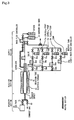
- FIG. 2 is a general view.
- the vaporization section 22 includes the vaporization tube 20 and the heating means (heater) 21.
- the heater 21 is a heater for heating and vaporizing the carrier gas in which the raw material solution is dispersed, flowing in the vaporization tube 20.
- the heater 21 has conventionally been formed by affixing a cylindrical heater or a mantle heater at the outer periphery of the vaporization tube 20.
- a method in which a liquid or a gas having high heat capacity is used as a heating medium is most excellent. Therefore, this method was used in this example.
- the vaporization tube 20 stainless steel, for example, SUS316L is preferably used.
- the dimensions of the vaporization tube 20 may be determined appropriately so that its length is enough to heat the vaporized gas. For example, when a SrBi 2 Ta 2 O 9 raw material solution of 0.04 ccm is vaporized, the vaporization tube 20 having an outside diameter of 3/4 inches and a length of several hundred millimeters can be used.
- the downstream side end of the vaporization tube 20 is connected to a reaction tube of an MOCVD apparatus.
- an oxygen supply port 25 is provided on the vaporization tube 20 as oxygen supply means so that oxygen heated to a predetermined temperature can be fed to the carrier gas.
- reserve tanks 32a, 32b, 32c and 32d are connected to the raw material supply port 6 via mass-flow controllers 30a, 30b, 30c and 30d and valves 31a, 31b, 31c and 31d, respectively.
- the reserve tanks 32a, 32b, 32c and 32d are connected with a carrier gas bomb 33.
- the reserve tank is filled with the raw material solution.
- the carrier gas for example, inert gas Ar, He, Nc
- the carrier gas for example, inert gas Ar, He, Nc
- the carrier gas of, for example, 1.0 to 3.0 kgf/cm 2 is sent into each of the reserve tanks (content volume: 300 cc, made of SUS). Since the interior of the reserve tank is pressurized by the carrier gas, the raw material solution is pushed up in the tube on the side contacting with the solution, and is sent under pressure to the liquid mass-flow controller (manufactured by STEC, full-scale flow rate: 0.2 cc/min), where the flow rate is controlled.
- the raw material solution is conveyed to the raw material supply hole 6 through a raw material supply inlet 29 of the vaporizer.
- the raw material solution whose flow rate has been controlled to a fixed value by the mass-flow controller, is conveyed to a reaction section by the carrier gas.
- oxygen oxidizing agent
- a mass-flow controller manufactured by STEC, full-scale flow rate: 2 L/min
- the valves 31b, 31c and 31d were opened, and the carrier gas was sent under pressure into the reserve tanks 32b, 32c and 32d.
- the raw material solution is sent under pressure to the mass-flow controller (manufactured by STEC, full-scale flow rate: 0.2 cc/min), where the flow rate is controlled.
- the raw material solution is conveyed to the raw material supply hole 6 of the vaporizer.
- the carrier gas was introduced through the gas introduction port of the vaporizer.
- the maximum pressure on the supply port side is preferably equal to or lower than 3 kgf/cm 2 .
- the maximum flow rate of gas capable of passing through is about 1200 cc/min, and the flow velocity in the gas passage 2 reaches one hundred and several tens meters per second.
- the raw material solution When the raw material solution is introduced through the raw material supply hole 6 to the carrier gas flowing in the gas passage 2 of the vaporizer, the raw material solution is sheared by the high-velocity flow of carrier gas and changed to ultrafine particles. As a result, the raw material solution is dispersed in the carrier gas in an untrafine particle state.
- the carrier gas in which the raw material solution is dispersed in an untrafine particle state (raw material gas) is atomized as being in a high-velocity state by the vaporization section 22 and is released.
- the angle formed between the gas passage and the raw material supply hole is optimized. In the case where the angle between a carrier flow path and a raw material solution introduction port is an acute angle (30 degrees), the solution is drawn by the gas.
- the solution is pushed by the gas.
- the optimum angle is determined from the viscosity and flow rate of solution. When the viscosity or the flow rate is high, the solution is caused to flow smoothly by making the angle more acute. In the case where hexane is used as the solvent to form an SBT film, an angle of about 84 degrees is preferable because both viscosity and flow rate are low.
- the vaporization of the raw material solution which is released from the dispersion section 8 and dispersed in the carrier gas in a fine particle form, is accelerated during the conveyance in the vaporization tube 20 heated to a predetermined temperature by the heater 21.
- a mixed gas is formed, and flows into the reaction tube.
- evaluation was carried out by analyzing the reaction mode of vaporized gas in place of film formation.
- a vacuum pump (not shown) was connected from an exhaust outlet 42 to remove water and other impurities in the reaction tube 44 by means of an evacuating operation for about 20 minutes, and a valve 40 on the downstream side of the exhaust outlet 42 was closed.
- Cooling water was caused to flow in the vaporizer at a flow rate of about 400 cc/min.
- a carrier gas of 3 kgf/cm 2 was caused to flow at a flow rate of 495 cc/min.
- the valve 40 was opened. The temperature at the gas outlet 7 was lower than 67°C.
- the interior of the vaporization tube 20 was heated to 200°C, a section from the reaction tube 44 to a gas pack 46 and the gas pack were heated to 100°C, and the interior of the reaction tube 44 was heated to 300°C to 600°C.
- the interior of the reserve tank was pressurized by the carrier gas, and a predetermined liquid was caused to flow by the mass-flow controller.
- reaction product was analyzed with a gas chromatograph, and it was examined whether the detected product coincided with the product in the reaction formula studied based on the reaction theory. As a result, in this example, the detected product coincided well with the product in the reaction formula studied based on the reaction theory.
- the amount of carbides adhering to the external surface on the gas outlet 7 side of the dispersion section body 1 was measured. As the result, the amount of adhering carbides was very small, and was further smaller than in the case where the apparatus shown in Figure 14 was used.
- the raw material solution in which a metal to be used as a film raw material is mixed with or dissolved in a solvent, the raw material solution is generally such that the metal becomes a complex and in a liquid/liquid state (perfect solvent solution).
- the metal complex is not necessarily in a scattered molecular state, and the metal complex itself is present as fine particles with a size of 1 to 100 nm in the solvent in some cases or is partially present as a solid/liquid state. It is considered that the clogging at the time of vaporization is liable to occur especially when the raw material solution is in such a state.
- the evaporator in accordance with the present invention is used, clogging does not occur even when the raw material solution is in such a state.
- the fine particles are liable to settle at the bottom by means of the gravity thereof. Therefore, to prevent clogging, it is preferable that convection be caused in the solution by heating the bottom portion (to a temperature equal to or lower than the evaporating temperature of solvent) to homogeneously disperse the fine particles. Also, it is preferable that not only the bottom portion be heated but also the side face of the container upper surface be cooled. Needless to say, the heating is performed at a temperature equal to or lower than the evaporating temperature of solvent.
- a heater set or control the quantity of heat for heating the evaporation tube upper region so as to be larger than the quantity of heat for heating the downstream region.
- a heater that sets or controls the quantity of heat for heating so that the quantity of heat is large in the evaporation tube upper region and is small in the downstream region.
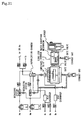
- the means for containing the solvent in the carrier gas is configured as described below in this example.
- a solvent 401 is stored beforehand in a container 400, and a carrier gas 403 is sent into the solvent to bubble the solvent. After the bubbling, the carrier gas is introduced to the gas introduction port 4.
- the raw materials of SBT are organic metal complexes dissolved in an organic solvent n-hexane C 6 H 14 (boiling point at a pressure of 760 Torr is 68.7°C, melting point is - 95.8°C) of hexa-ethoxy-strontiumtantalum Sr(OC 2 H 5 ) 2 [Ta(OC 2 H 5 ) 5 ] 2 (boiling point at a pressure of 0.1 Torr is 176°C, melting point is 130°C) and tri-t-amyloxybismuth Bi(0-t-C 5 H 11 ) 3 (boiling point at a pressure of 0.1 Torr is 87°C(sublimation)).
- the supply condition of raw material is 0.02 cc/min for organic metal complex of hexa-ethoxy-strontiumtantalum Sr(OC 2 H 5 ) 2 [Ta(OC 2 H 5 ) 5 ] 2 .
- the supply condition of raw material is also 0.02 cc/min for organic metal complex of tri-t-amyloxybismuth Bi(O-t-C 5 H 11 ) 3 .
- the supply quantity of argon, which is an inert gas is 200 (NTP)/min, and the supply quantity of oxygen is 10 (NTP)/min.
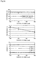
- the film composition does not change even if the supply quantity of reaction oxygen is changed, and a composition of SrBi 2 Ta 2 O 2 can substantially be obtained. Also, it is found that even if the quantity of reaction oxygen is changed greatly, the thickness of SBT thin film is about 2000 X in 20 minutes.
- the pressure of reactor is kept constant, and the flow rate of reaction oxygen is increased, the partial pressure of oxygen in the reactor increases, but the partial pressure of raw material decreases. This means that the number density of raw material molecules in the reactor decreases, and at the same time, the number of collisions of raw material molecules with the substrate decreases.
- the film formation rate should decrease along with the increase in flow rate of reaction oxygen.
- the film formation rate is constant regardless of the flow rate of reaction oxygen. This suggests that the grow rate of film is not determined by the number of collisions of raw material molecules, but is determined by the reaction on the surface of substrate.
- the operation for saturating the carrier gas (inert gas, or inert gas containing a predetermined oxygen) with solvent vapor has an effect that a raw material adjusted to a stoichiometric ratio can be supplied continuously and stably and the quantity of residual carbon in a formed film can be decreased.
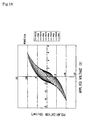
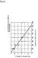
- the carbon content in the film can be decreased by increasing the flow rate of reaction oxygen. It can be seen from the central graph of the accompanying figure (relationship between the flow rate of oxygen and the quantity of residual carbon) that in order to render the carbon content in the film zero, oxygen should be supplied at a flow rate of about 1430 [cc(NTP)/min].
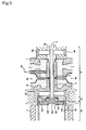
- Figure 5 shows a vaporizer for MOCVD in accordance with example 2.
- a cooling water passage 106 was formed at the outer periphery of the radiation preventive portion 102, and cooling means 50 was provided at the outer periphery of the connecting portion 23 to cool the radiation preventive portion 102.
- a concave portion 107 was provided around the outlet of the minute hole 101.
- the detected product coincided better with the product in the reaction formula studied based on the reaction theory than in the case of example 1.
- the amount of carbides adhering to the external surface on the gas outlet 7 side of the dispersion section body 1 was measured, with the result that the amount of adhering carbides was about 1/3 of the case of example 1.
- a solvent introduction passage 402 was provided. The solvent is introduced into the carrier gas 3 on the downstream side of the raw material supply hole 6 of the passage 2.
- a flow meter be provided on the upstream side of the solvent introduction passage 402. Also, it is preferable that a sensor for measuring the temperature of vaporization section and a sensor for measuring the flow rate and pressure of carrier gas in the passage be provided. The signals from these sensors are processed, and the saturated vapor pressure of solvent is calculated.
- the solvent is preferably introduced so as to always achieve the saturated vapor pressure by controlling the quantity of introduced solvent by using the flow meter.
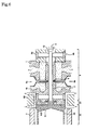
- Figure 6 shows a vaporizer for MOCVD in accordance with example 3.
- the radiation preventive portion 102 has a taper 51.
- This taper 51 eliminates a dead zone in this portion, so that the retention of raw material can be prevented.
- the detected product coincided better with the product in the reaction formula studied based on the reaction theory than in the case of example 2.
- Figure 7 shows modified examples of the gas passage.
- grooves 70 are formed in the surface of the rod 10, and the outside diameter of the rod 10 is almost the same as the inside diameter of the hole formed in the dispersion section body 1. Therefore, merely by inserting the rod 10 in the hole, the rod can be arranged in the hole without eccentricity. Also, machine screws etc. need not be used.
- the grooves 70 serve as gas passages.
- the grooves 70 may be formed in plural numbers in parallel with the axis in the lengthwise direction of the rod 10, or they may be formed in a spiral form in the surface of the rod 10. In the case of the spiral form, a raw material gas having high homogeneity can be obtained.
- Figure 7(b) shows an example in which mixing portions are provided in the tip end portion of the rod 10.
- the largest diameter in the tip end portion is almost the same as the inside diameter of the hole formed in the dispersion section body 1. Spaces formed by the rod tip end portion and the internal surface of hole serve as gas passages.
- Figures 7(a) and 7(b) are examples in which the surface of the rod 10 is machined. However, it is a matter of course that a rod having a circular cross section is used, and concave portions are formed in the surface of hole to provide gas passages. It is preferable that the rod be arranged in accordance with H7 x h6 - JS7 specified in JIS.
- Example 5 is explained with reference to Figure 8.
- the vaporizer for MOCVD of this example includes:
- the raw material solution 5 When the raw material solution 5 is supplied to the gas passage through which the high-velocity carrier gas 3 flows, the raw material solution is sheared and atomized. Specifically, the raw material solution, which is a liquid, is sheared by a high-velocity flow of carrier gas, and made particles. The raw material solution having been made particles is dispersed in the carrier gas in a particulate state. This point is the same as in example 1.
- the raw material solution 5 is supplied preferably at a rate of 0.005 to 2 cc/min, more preferably at a rate of 0.005 to 0.02 cc/min, and still more preferably at a rate of 0.1 to 0.3 cc/min.
- the total quantity thereof should preferably be as described above.
- the carrier gas is supplied preferably at a rate of 10 to 200 m/sec, more preferably at a rate of 100 to 200 m/sec.
- the spiral groove 60 is formed at the outer periphery of the rod 10, and a gap space is present between the dispersion section body 1 and the rod 10. Therefore, the carrier gas containing the atomized raw material solution goes straight in this gap space as a straight flow, and also forms a swirl flow along the spiral groove 60.
- the reason why uniform dispersion can be obtained if the straight flow and the swirl flow coexist is not necessarily clear. However, the following reason is possible.
- the existence of swirl flow produces a centrifugal force in the flow, and a secondary flow is produced. This secondary flow accelerates the mixing of the raw material with the carrier gas. That is, it is considered that a secondary derived flow is produced in the direction perpendicular to the flow by the centrifugal effect of swirl flow, and thereby the atomized raw material solution is dispersed uniformly in the carrier gas.
- the configuration is such that as one example, four kinds of raw material solutions 5a, 5b, 5c and 5d (5a, 5b and 5c are organic metal raw materials and 5d is a solvent raw material such as THF) are supplied to the gas passage.
- a portion in which the spiral groove is absent is provided on a downstream side of a portion corresponding to a raw material supply hole 6 of the rod 10.
- This portion serves as a premixing portion 65.
- the premixing portion 65 the raw material gas of three kinds of organic metals is mixed to some extent, and further a perfectly mixed raw material gas is formed in the region of the downstream spiral structure.
- the length of the mixing portion 65 is preferably 5 to 20 mm, more preferably 8 to 15 mm. If the length thereof is out of the above range, only on kind of mixed raw material gas with a high concentration of the raw material gases of three kinds of organic metals is sometimes sent to the vaporization section 22.
- an end portion 66 on the upstream side of the rod 10 is provided with a parallel portion 67 and a taper portion 58.
- a parallel portion having an inside diameter equal to the outside diameter of the parallel portion 67 of the rod 10, which corresponds to the parallel portion 67, and a taper portion with the same taper as the taper of the rod 10, which corresponds to the taper portion 58, are provided. Therefore, when the rod 10 is inserted from the left-hand side in the figure, the rod 10 is held in the hollow portion of the dispersion section body 1.
- the rod 10 since the rod 10 is held with the taper being provided, even if a carrier gas having a pressure higher than 3 kgf/cm 2 is used, the rod 10 can be prevented from moving. Specifically, if the holding technique shown in Figure 8 is employed, the carrier gas can be caused to flow at a pressure equal to or higher than 3 kgf/cm 2 . As a result, the cross-sectional area of gas passage is decreased, and a higher-velocity carrier gas can be supplied by a small quantity of gas. Specifically, a carrier gas with a high velocity of 50 to 300 mm/s can be supplied. The same is true if this holding technique is employed in the above-described other examples.
- grooves 67a, 67b, 67c and 67d are formed as carrier gas passages.
- the depth of each of the grooves 67a, 67b, 67c and 67d is preferably 0.005 to 0.1 mm. If the depth thereof is shallower than 0.005 mm, the machining of groove is difficult. Also, the depth thereof is more preferably 0.01 to 0.05 mm. The depth in this range prevents the occurrence of clogging etc. Also, it can easily provide a high-velocity flow.
- the number of the spiral grooves 60 may be one as shown in Figure 9(a), or may be any plural numbers as shown in Figure 10. Also, when the plurality of spiral grooves are formed, they may be crossed. When the spiral grooves 60 are crossed, a raw material gas dispersed more uniformly can be obtained. However, the cross-sectional area should be such that a gas flow velocity equal to or higher than 10 m/sec can be obtained in each groove.
- the size and shape of the spiral groove 60 is not subject to any special restriction.
- the size and shape shown in Figure 9(c) is one example.
- the gas passage is cooled by cooling water 18.
- an expansion section 69 is independently provided in front of the inlet of the dispersion section 22, and the lengthwise radiation preventive portion 102 is arranged in this expansion section 69.
- the minute hole 101 is formed on the gas outlet 7 side of the radiation preventive portion, and the inside diameter of the minute hole 101 spreads in a taper shape toward the vaporizer side.
- the expansion section 69 also serves to prevent the retention of raw material gas, which has been described in example 3. Needless to say, there is no need for independently provide the expansion section 69.
- the integrated construction as shown in Figure 6 may also be used.
- the expansion angle ⁇ of the expansion section 69 is preferably 5 to 10 degrees. When the expansion angle ⁇ is within this range, the raw material gas can be supplied to the dispersion section without destroying the swirl flow. Also, when the expansion angle ⁇ is within this range, the fluid resistance due to expansion becomes a minimum and also the presence of dead zone becomes a minimum, so that the presence of eddy current due to the presence of dead zone can be made a minimum.
- the expansion angle ⁇ is more preferably 6 to 7 degrees. In the case of the example shown in Figure 6 as well, the preferable range of ⁇ is the same.
- the apparatus shown in Figure 8 As a vaporizing apparatus, the apparatus shown in Figure 8 was used. As a rod, the rod shown in Figure 9, which is not formed with the spiral groove, was used.
- the raw material solutions were supplied from the raw material supply hole 6, and the carrier gas was supplied by changing the velocity thereof variously.
- Sr(DPM) 2 was supplied to the groove 67a
- Bi(C 6 H 5 ) 3 was supplied to the groove 67b
- Ta(OC 2 H 5 ) 5 was supplied to the groove 67c
- THF and other solvents were supplied to the groove 67d.
- Heating was not performed in the vaporization section, and the raw material gas was sampled at the gas outlet 7 to measure the particle diameter of raw material solution in the sampled raw material gas.
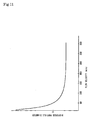
- the measurement result is shown in Figure 11 as a relative value (the case where the apparatus of the conventional example shown in Figure 12(a) is taken as 1).
- Figure 11 by rendering the flow velocity equal to or higher than 50 m/s, the dispersed particle diameter decreases, and by rendering the flow velocity equal to or higher than 100 m/s, the dispersed particle diameter further decreases.
- the flow velocity is rendered equal to or higher than 200 m/s, the dispersed particle diameter saturates. Therefore, the preferred range is 100 to 200 m/s.
- the concentration of raw material solution supplied to the groove was high.
- the concentration of Sr(DPM) 2 was high
- the concentration of Bi(C 6 H 5 ) 3 was high
- the concentration of Ta(OC 2 H 5 ) 5 was high.
- each organic metal raw material was uniform in any portions.
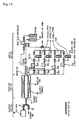
- Example 8 is shown in Figures 12 and 13.
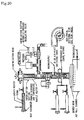
- the inventor found that the cause for this relates to the introduction position of oxygen. Specifically, it was found that as shown in Figure 20, if oxygen is introduced, together with the carrier gas, from the gas introduction port 4, a secondary oxygen supply port 200 just near a blowoff port, and a oxygen introduction port (primary oxygen supply port) 25, the difference in percentage composition between the composition in the formed film and the composition in the raw material solution can be made extremely small.
- the conditions of vaporizer and reaction chamber were controlled as described below, and an SBT film was formed on a substrate obtained by forming platinum of 200 nm on an oxidized silicon substrate.
- the difference in percentage composition between the composition in the formed film and the composition in the raw material solution was very small, and the deposition speed was about five times the conventional speed. It is found that the effect of introducing small amount of oxygen through the gas introduction port 4 together with the carrier gas is extremely great.
- the carbon content is as low as 3.5 at%.
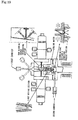
- an oxidizing gas such as oxygen is merely introduced through the gas introduction port 4 or a primary oxygen supply port just near a blowoff port, it is preferable that, as shown in figure 2, oxygen be introduced at the same time on the downstream side of a vaporization section and the quantity of oxygen be controlled appropriately, because by doing this, the difference in percentage composition is further decreased and the carbon content is also decreased.
- the content of carbon in the formed film can be decreased to 5 to 20% of the conventional example.
- a valve 2 is opened, and a valve 1 is closed, by which a reaction chamber is evacuated to a high vacuum. After several minutes, a wafer is transferred from a load lock chamber to a reaction chamber.
- the pressure gage is controlled to 4 Torr by the automatic pressure regulating valve.
- valve 1 When the temperature becomes stable several minutes after the wafer has been transferred, the valve 1 is opened, and the valve 2 is closed, by which the following gas is caused to flow into the reaction chamber to start deposition.
- the reaction pressure chamber pressure is controlled to 1 Torr (by a not described automatic pressure regulating valve).
- valve 2 After predetermined time (20 minutes, in this example) has elapsed, the valve 2 is opened, and the valve 1 is closed, by which the deposition is finished.
- the reaction chamber is evacuated to a high vacuum to remove the reaction gas completely, and after one minute, the wafer is taken out to the load lock chamber.
- reaction oxygen for example, 200 sccm
- the organic metal gas has been cooled, and adhered to and deposited in the vaporization tube.
- a heater has been wound around a stainless steel tube (outside dimension: 1/4 to 1/16 inch, length: 10 to 100 cm) to control the temperature of external wall of the stainless steel tube (to 219°C, for example).
- the temperature of external wall of the stainless steel tube (219°C, for example) is equal to the temperature of oxygen (flow rate: 200 sccm) flowing inside.
- the temperature of oxygen after being heated was measured directly with a minute thermocouple, and the heater temperature was controlled, by which the oxygen temperature was controlled accurately.
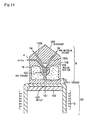
- Example 10 is shown in Figure 14.
- gas is blown to each of the raw material solutions to atomize the single raw material solution, and subsequently, the atomized raw material solutions are mixed with each other.
- This example provides an apparatus in which a plurality of raw material solutions are mixed, and then the mixed raw material solutions are atomized.
- the evaporator of this example includes:
- This example is effective for the raw material solutions the reaction of which does not proceed even if being mixed. Since the raw material solutions are atomized after being once mixed, the composition is exact as compared with the case where the raw material solutions are mixed after being atomized. Also, means (not shown) for analyzing the composition of mixed raw material solution in the mixing section 109 is provided, and the supply amounts of the raw material solutions 5a and 5b are controlled based on the analysis result, by which more exact composition can be obtained.
- a rod (reference numeral 10 in Figure 1) need not be used. Therefore, the heat propagating in the rod does not heat the interior of the supply passage 110. Further, the cross-sectional area of the supply passage 110 can be decreased as compared with the case where the raw material solutions are mixed after being atomized, and hence the cross-sectional area of the outlet 107 can be decreased, so that the interior of the supply passage 110 is scarcely heated by radiation. Therefore, the deposition of crystals can be decreased without providing the radiation preventive portion 102. In the case where it is desirable to further prevent the deposition of crystals, the radiation preventive portion 102 may be provided as shown in Figure 14.
- the number of minute holes is one in the above-described examples, it is a matter of course that the number of minute holes may be plural. Also, the diameter of the minute hole is preferably equal to or smaller than 2 mm. When a plurality of minute holes are provided, the diameter can be made far smaller.
- the carrier flow path and the raw material solution introduction port make an acute angle (30 degrees)
- the solution is drawn by the gas. If the angle is equal to or larger than 90 degrees, the solution is pushed by the gas. Therefore, the angle is preferably 30 to 90°.
- the optimum angle is determined from the viscosity and flow rate of solution. When the viscosity is high or the flow rate is high, the solution is caused to flow smoothly by making the angle more acute. Therefore, in implementation, the optimum angle corresponding to the viscosity and flow rate has only to be determined in advance by an experiment etc.
- a liquid mass-flow controller for controlling the flow rate of raw material solution be provided, and degassing means for gas removal be provided on the upstream side of the liquid mass-flow controller. If degassing is not accomplished and the raw material solution is introduced to the mass-flow controller, variations in the formed films occur on the same wafer or between wafers. By introducing the raw material solution to the mass-flow controller after the removal of helium etc., the above-described variations in film thickness are decreased remarkably.
- the variations in film thickness can further be prevented. Also, the change of properties of a chemically unstable raw material solution can be prevented.
- control is precisely carried out in the range of 5 to 20°C. The range of 12°C ⁇ 1°C is especially preferable.
- a heating medium circulation path having an upstream ring 301 connected to a heating medium inlet 320 for once-through flow of heating medium, a downstream ring 302 connected to a heating medium outlet 321 for a predetermined heating medium, and at least two heat transfer paths 303a and 303b which connect the upstream ring 1 and the downstream ring 2 to each other in the parallel direction, for making the gas at a predetermined temperature by alternating the flow path direction from the upstream ring 1 to the downstream ring 302 between the adjacent heat transfer paths 303a and 303b.
- the substrate surface treatment apparatus preferably has a heat conversion plate 304 thermally connected to the heating medium circulation path in a predetermined plane in the heating medium circulation path and in a plane formed in the flow path of the heating medium in the parallel direction so that the portion in the plane of the heat conversion plate 304 can be heated to a substantially uniform temperature by the heating medium.
- a plurality of vent holes for causing the predetermined gas to pass through in the vertical direction of the plane are preferably formed so that the predetermined gas passing through the vent hole can be heated to a substantially uniform temperature in the plane.
- the configuration is such that the flow path direction from the upstream ring to the downstream ring between the adjacent heat transfer paths of the heating medium circulation path is alternated. Therefore, the difference in temperature in the regions adjacent to the heat transfer path is configured so as to be high/low/high/low ....
- the heat conversion plate can be heated or cooled uniformly.
- a heat conversion plate thermally connected to the heating medium circulation path is provided in a plane formed in the flow path of heating medium in the parallel direction. Therefore, a portion in the plane of this heat conversion plate can be heated to a substantially uniform temperature by the heating medium.
- the present invention can be applied to all vaporizers.
- the solvent contained in the carrier gas may be a gas or may be a liquid, also may be the same solvent as the solvent for the raw material solution or may be a different solvent from the solvent for the raw material solution.
- a vaporizer used for a film forming apparatus such as a MOCVD film forming apparatus and other apparatuses, which can be used for a long period of time without being clogged, and can supply raw materials stably to a reaction section.
- a vaporized gas in which an organic metal material is dispersed uniformly can be obtained.
Landscapes
- Chemical & Material Sciences (AREA)
- General Chemical & Material Sciences (AREA)
- Chemical Kinetics & Catalysis (AREA)
- Engineering & Computer Science (AREA)
- Materials Engineering (AREA)
- Mechanical Engineering (AREA)
- Metallurgy (AREA)
- Organic Chemistry (AREA)
- Dispersion Chemistry (AREA)
- Inorganic Chemistry (AREA)
- Chemical Vapour Deposition (AREA)
Applications Claiming Priority (3)
| Application Number | Priority Date | Filing Date | Title |
|---|---|---|---|
| JP2002156521 | 2002-05-29 | ||
| JP2002156521 | 2002-05-29 | ||
| PCT/JP2003/006766 WO2003100840A1 (fr) | 2002-05-29 | 2003-05-29 | Evaporateur, differents appareils l'incorporant et procede de vaporisation |
Publications (1)
| Publication Number | Publication Date |
|---|---|
| EP1533835A1 true EP1533835A1 (de) | 2005-05-25 |
Family
ID=29561488
Family Applications (1)
| Application Number | Title | Priority Date | Filing Date |
|---|---|---|---|
| EP03733161A Withdrawn EP1533835A1 (de) | 2002-05-29 | 2003-05-29 | Verdampfer, verschiedene, diesen enthaltende vorrichtungen und verdampfungsverfahren |
Country Status (7)
| Country | Link |
|---|---|
| US (1) | US20060037539A1 (de) |
| EP (1) | EP1533835A1 (de) |
| JP (1) | JP4391413B2 (de) |
| KR (1) | KR20050113549A (de) |
| AU (1) | AU2003241915A1 (de) |
| TW (1) | TW200401841A (de) |
| WO (1) | WO2003100840A1 (de) |
Cited By (1)
| Publication number | Priority date | Publication date | Assignee | Title |
|---|---|---|---|---|
| US8186301B2 (en) | 2005-05-27 | 2012-05-29 | Kirin Beer Kabushiki Kaisha | Apparatus for manufacturing gas barrier plastic container, method for manufacturing the container, and the container |
Families Citing this family (15)
| Publication number | Priority date | Publication date | Assignee | Title |
|---|---|---|---|---|
| JP2008196479A (ja) * | 2007-02-09 | 2008-08-28 | Sulzer Chemtech Ag | 排気ガス浄化システム |
| JP5427344B2 (ja) * | 2007-05-23 | 2014-02-26 | 株式会社渡辺商行 | 気化装置、及び、気化装置を備えた成膜装置 |
| US8512934B2 (en) | 2007-10-10 | 2013-08-20 | Basf Se | Sulphonium salt initiators |
| KR101234409B1 (ko) * | 2009-09-30 | 2013-02-18 | 시케이디 가부시키가이샤 | 액체 기화 시스템 |
| WO2012118019A1 (ja) * | 2011-02-28 | 2012-09-07 | 株式会社渡邊商行 | 気化器および気化器に用いられるセンターロッド、ならびにキャリアガスに同伴される原料などの気化方法 |
| WO2013038484A1 (ja) * | 2011-09-13 | 2013-03-21 | 東芝三菱電機産業システム株式会社 | 酸化膜成膜方法および酸化膜成膜装置 |
| JP6695701B2 (ja) * | 2016-02-03 | 2020-05-20 | 株式会社Screenホールディングス | 処理液気化装置と基板処理装置 |
| KR102483924B1 (ko) * | 2016-02-18 | 2023-01-02 | 삼성전자주식회사 | 기화기 및 이를 구비하는 박막 증착 장치 |
| FR3050254B1 (fr) * | 2016-04-13 | 2018-03-30 | Commissariat A L'energie Atomique Et Aux Energies Alternatives | Dispositif de conversion d'un liquide en vapeur |
| US10147597B1 (en) * | 2017-09-14 | 2018-12-04 | Lam Research Corporation | Turbulent flow spiral multi-zone precursor vaporizer |
| WO2020051385A1 (en) | 2018-09-06 | 2020-03-12 | Bergstrom Sam | Vaporizer apparatuses and vaporizing methods |
| US11413556B2 (en) | 2018-11-29 | 2022-08-16 | Tsi Incorporated | Reducing or eliminating liquid de-gassing |
| WO2020251696A1 (en) | 2019-06-10 | 2020-12-17 | Applied Materials, Inc. | Processing system for forming layers |
| TW202146701A (zh) * | 2020-05-26 | 2021-12-16 | 荷蘭商Asm Ip私人控股有限公司 | 氣相沉積系統、在基材上形成氮化釩層之方法、直接液體注入系統 |
| JP7577382B2 (ja) * | 2021-03-11 | 2024-11-05 | 株式会社フジキン | 気化器および気化供給装置 |
Family Cites Families (14)
| Publication number | Priority date | Publication date | Assignee | Title |
|---|---|---|---|---|
| US5776254A (en) * | 1994-12-28 | 1998-07-07 | Mitsubishi Denki Kabushiki Kaisha | Apparatus for forming thin film by chemical vapor deposition |
| JP3612839B2 (ja) * | 1996-02-13 | 2005-01-19 | 三菱電機株式会社 | 高誘電率薄膜構造、高誘電率薄膜形成方法および高誘電率薄膜形成装置 |
| TW346676B (en) * | 1996-05-14 | 1998-12-01 | Matsushita Electron Co Ltd | Method of manufacturing layered ferroelectric Bi containing film |
| US5835677A (en) * | 1996-10-03 | 1998-11-10 | Emcore Corporation | Liquid vaporizer system and method |
| US6271498B1 (en) * | 1997-06-23 | 2001-08-07 | Nissin Electric Co., Ltd | Apparatus for vaporizing liquid raw material and method of cleaning CVD apparatus |
| JP3470055B2 (ja) * | 1999-01-22 | 2003-11-25 | 株式会社渡邊商行 | Mocvd用気化器及び原料溶液の気化方法 |
| US6267820B1 (en) * | 1999-02-12 | 2001-07-31 | Applied Materials, Inc. | Clog resistant injection valve |
| JP2000345345A (ja) * | 1999-06-04 | 2000-12-12 | Mitsubishi Electric Corp | Cvd装置およびcvd装置用気化装置 |
| JP2000353700A (ja) * | 1999-06-14 | 2000-12-19 | Mitsubishi Electric Corp | 高誘電率薄膜の形成方法および半導体装置の製造方法 |
| EP1211333A3 (de) * | 2000-12-01 | 2003-07-30 | Japan Pionics Co., Ltd. | Verdampfer für CVD-Anlage |
| KR100881681B1 (ko) * | 2001-01-18 | 2009-02-06 | 가부시키가이샤 와타나베 쇼코 | 기화기 및 이를 이용한 각종 장치와 기화 방법 |
| JP2002289556A (ja) * | 2001-03-27 | 2002-10-04 | Fujitsu Ltd | 成膜用治具及びその製造方法並びに半導体装置の製造装置 |
| JP2003268552A (ja) * | 2002-03-18 | 2003-09-25 | Watanabe Shoko:Kk | 気化器及びそれを用いた各種装置並びに気化方法 |
| JP2004273766A (ja) * | 2003-03-07 | 2004-09-30 | Watanabe Shoko:Kk | 気化装置及びそれを用いた成膜装置並びに気化方法及び成膜方法 |
-
2003
- 2003-05-29 EP EP03733161A patent/EP1533835A1/de not_active Withdrawn
- 2003-05-29 JP JP2004508397A patent/JP4391413B2/ja not_active Expired - Fee Related
- 2003-05-29 AU AU2003241915A patent/AU2003241915A1/en not_active Abandoned
- 2003-05-29 KR KR1020047019138A patent/KR20050113549A/ko not_active Ceased
- 2003-05-29 US US10/515,888 patent/US20060037539A1/en not_active Abandoned
- 2003-05-29 WO PCT/JP2003/006766 patent/WO2003100840A1/ja not_active Ceased
- 2003-05-29 TW TW092114533A patent/TW200401841A/zh unknown
Non-Patent Citations (1)
| Title |
|---|
| See references of WO03100840A1 * |
Cited By (2)
| Publication number | Priority date | Publication date | Assignee | Title |
|---|---|---|---|---|
| US8186301B2 (en) | 2005-05-27 | 2012-05-29 | Kirin Beer Kabushiki Kaisha | Apparatus for manufacturing gas barrier plastic container, method for manufacturing the container, and the container |
| US8808797B2 (en) | 2005-05-27 | 2014-08-19 | Kirin Beer Kabushiki Kaisha | Method of manufacturing a gas barrier plastic container |
Also Published As
| Publication number | Publication date |
|---|---|
| WO2003100840A1 (fr) | 2003-12-04 |
| US20060037539A1 (en) | 2006-02-23 |
| KR20050113549A (ko) | 2005-12-02 |
| JP4391413B2 (ja) | 2009-12-24 |
| TW200401841A (en) | 2004-02-01 |
| AU2003241915A1 (en) | 2003-12-12 |
| JPWO2003100840A1 (ja) | 2005-09-29 |
Similar Documents
| Publication | Publication Date | Title |
|---|---|---|
| EP1492160A1 (de) | Verdampfer, verschiedene, diesen verwendende einrichtungen und verdampfungsverfahren | |
| EP1361610B1 (de) | Verdampfer und die beschictungsvorrichtung mit dem verdampfer | |
| US6931203B2 (en) | Vaporizer for MOCVD and method of vaporizing raw material solutions for MOCVD | |
| JP2004273766A (ja) | 気化装置及びそれを用いた成膜装置並びに気化方法及び成膜方法 | |
| US20060037539A1 (en) | Vaporizer, various apparatuses including the same and method of vaporization | |
| EP1492159A1 (de) | Verfahren zum ablagern eines cvd-dünnfilms | |
| JP5016416B2 (ja) | 気化器及び気化方法 | |
| JP2008211206A (ja) | 強誘電体薄膜・金属薄膜又は酸化物薄膜及びその製造方法・製造装置並びに該薄膜を用いた電子・電気デバイス | |
| JP4238239B2 (ja) | 気化方法 | |
| JP2008205506A (ja) | 気化器及びそれを用いた各種装置並びに気化方法 | |
| JP2008300871A (ja) | 気化器、薄膜形成装置及びmocvd装置 | |
| JP2007258733A (ja) | 気化方法及び成膜方法 |
Legal Events
| Date | Code | Title | Description |
|---|---|---|---|
| PUAI | Public reference made under article 153(3) epc to a published international application that has entered the european phase |
Free format text: ORIGINAL CODE: 0009012 |
|
| 17P | Request for examination filed |
Effective date: 20041213 |
|
| AK | Designated contracting states |
Kind code of ref document: A1 Designated state(s): AT BE BG CH CY CZ DE DK EE ES FI FR GB GR HU IE IT LI LU MC NL PT RO SE SI SK TR |
|
| AX | Request for extension of the european patent |
Extension state: AL LT LV MK |
|
| DAX | Request for extension of the european patent (deleted) | ||
| STAA | Information on the status of an ep patent application or granted ep patent |
Free format text: STATUS: THE APPLICATION HAS BEEN WITHDRAWN |
|
| 18W | Application withdrawn |
Effective date: 20090609 |