EP1533614B1 - Carte test pour la détermination de substances dans un échantillon liquide ou gazeux et sa procédé de production - Google Patents
Carte test pour la détermination de substances dans un échantillon liquide ou gazeux et sa procédé de production Download PDFInfo
- Publication number
- EP1533614B1 EP1533614B1 EP04026357A EP04026357A EP1533614B1 EP 1533614 B1 EP1533614 B1 EP 1533614B1 EP 04026357 A EP04026357 A EP 04026357A EP 04026357 A EP04026357 A EP 04026357A EP 1533614 B1 EP1533614 B1 EP 1533614B1
- Authority
- EP
- European Patent Office
- Prior art keywords
- sensor
- film
- openings
- card according
- intermediate film
- Prior art date
- Legal status (The legal status is an assumption and is not a legal conclusion. Google has not performed a legal analysis and makes no representation as to the accuracy of the status listed.)
- Not-in-force
Links
Images


Classifications
-
- G—PHYSICS
- G01—MEASURING; TESTING
- G01N—INVESTIGATING OR ANALYSING MATERIALS BY DETERMINING THEIR CHEMICAL OR PHYSICAL PROPERTIES
- G01N27/00—Investigating or analysing materials by the use of electric, electrochemical, or magnetic means
- G01N27/26—Investigating or analysing materials by the use of electric, electrochemical, or magnetic means by investigating electrochemical variables; by using electrolysis or electrophoresis
- G01N27/28—Electrolytic cell components
- G01N27/30—Electrodes, e.g. test electrodes; Half-cells
- G01N27/333—Ion-selective electrodes or membranes
-
- G—PHYSICS
- G01—MEASURING; TESTING
- G01N—INVESTIGATING OR ANALYSING MATERIALS BY DETERMINING THEIR CHEMICAL OR PHYSICAL PROPERTIES
- G01N33/00—Investigating or analysing materials by specific methods not covered by groups G01N1/00 - G01N31/00
- G01N33/48—Biological material, e.g. blood, urine; Haemocytometers
- G01N33/483—Physical analysis of biological material
- G01N33/487—Physical analysis of biological material of liquid biological material
- G01N33/49—Blood
- G01N33/492—Determining multiple analytes
-
- Y—GENERAL TAGGING OF NEW TECHNOLOGICAL DEVELOPMENTS; GENERAL TAGGING OF CROSS-SECTIONAL TECHNOLOGIES SPANNING OVER SEVERAL SECTIONS OF THE IPC; TECHNICAL SUBJECTS COVERED BY FORMER USPC CROSS-REFERENCE ART COLLECTIONS [XRACs] AND DIGESTS
- Y10—TECHNICAL SUBJECTS COVERED BY FORMER USPC
- Y10T—TECHNICAL SUBJECTS COVERED BY FORMER US CLASSIFICATION
- Y10T156/00—Adhesive bonding and miscellaneous chemical manufacture
- Y10T156/10—Methods of surface bonding and/or assembly therefor
Definitions
- the present invention relates to a sensor card for the determination of analytes in liquid or gas samples with surface-connected films. Furthermore, the invention relates to a method for producing such a sensor card.
- Such sensor cards are used in measuring instruments or analysis systems in which a liquid or gas sample is subjected to a chemical analysis, wherein the quantitative determination of different analytes in gaseous and liquid samples is possible.
- analysis systems are increasingly used in medical technology, process control and food and environmental analysis.
- the analysis of parameters of body fluids in the context of point-of-care (POC) testing in the field of medical diagnostics represents a major field of application of these analysis systems.
- POC point-of-care
- these blood parameters include the blood gases (pO 2 , pCO 2 , pH), the electrolytes (Na, K, Ca, Cl), the conductivity of the blood and derived therefrom the hematocrit and the metabolites (glucose, lactate, urea, creatinine).
- the location of the analysis is shifted from the central laboratory to the vicinity of the patient. The analyzes therefore no longer have to be carried out by specialized laboratory personnel, but can be carried out by the staff who also looks after the patient. This results in a considerable amount of time gained, which benefits a faster and more efficient treatment of the patient.
- Newer analyzers are increasingly using maintenance-free planar sensors, including: can be produced in large series using methods of thin and thick film technology.
- Several sensors each of which can specifically determine an analyte, are applied to a substrate.
- In the flow cell calibration solution and liquid sample are given via the sensors to determine the analyte concentrations.
- the known sensor cards with double-matrix membrane have a sensor film with openings, which faces the liquid sample to be examined in the position of use.
- a cover sheet is arranged, on which electrical conductor tracks of silver / silver chloride are printed, these conductor tracks facing the sensor film.
- Support materials for ion-selective DMM sensors are arranged between the sensor film and the cover film, which on the one hand adjoin an opening in the sensor film and, on the other hand, one of the conductor tracks on the cover film.
- the films and the sensors connected wherein the openings in the sensor film are formed smaller than the sensor surface, so that the edge of the opening depresses the edge of the sensor, which ultimately leads to an increase of the edge of the opening, the electrical tap is directly on the conductor tracks, which to extend this purpose to the edge of the cover sheet, which is formed larger than the sensor film, so that a part of the conductor is not covered by the sensor film and can be tapped.
- the known DMM sensor card is connected flat to a plate in which there are one or more grooves. This connection creates a flow channel for the liquid sample which is bounded on the one hand by the wall of the grooves and on the other hand by the sensor foil of the DMM sensor card.
- the openings in the sensor film in this case point to the flow channel, so that the sensors can be wetted with the fluid sample flowing through the flow channel.
- the known DMM Sensox card has the disadvantage that it does not ensure a reliable seal of the flow channels within the plate.
- the DE 197 47 875 A1 describes a sensor card that has a sensor foil, a cover foil and an intermediate foil.
- a sensor In a recess of the intermediate parts is a sensor.
- the electrical tap is made via contacts and contact strips, which led to contact lugs.
- the contacts, contact tracks and lugs are on the side of the cover sheet, which faces the intermediate film.
- the sensor comes into contact with the sample via an opening in the sensor film.
- the contacting of the sensor is disadvantageous insofar as contact paths and contact lugs are applied on the side of the cover film which faces the intermediate film. This creates the problem that the tabs can not be tapped easily.
- the problem is solved in that the cover film on the one hand and the intermediate and sensor film on the other hand are arranged one above the other so that the region of the cover film, on which the contact lugs are arranged, protrudes outward.
- the WO 02/097415 A2 describes an oxygen sensor having a working electrode, a reference electrode and a ground electrode.
- the working electrode has a platinum wire which sits in the center of a glass pane. On one side of the glass pane, the platinum wire is covered with two membranes, while the wire on the other side of the pane is contacted with an electrode. The platinum wire is exposed on the side facing away from the contact with the electrode, a gas stream, while the electrical tap on the side of contacting with the electrode takes place.
- the present invention is therefore based on the object to provide a sensor card for the determination of analytes in liquid samples, which ensures a secure seal of the flow channels for the liquid sample, and to provide a method for producing such a sensor card.
- the sensor card according to the invention for the determination of analytes in liquid or gas samples has two-dimensionally interconnected films.
- the film facing the liquid sample is referred to as a sensor film and is provided with openings.
- facing the liquid sample means that the sensor film with the fluid sample inside the Flow channels comes into contact, ie the sensor card is later, as already described with reference to the prior art, be connected flat with the plate in which the grooves are located.
- the sensor card also has a cover sheet facing away from the sample, ie, the cover sheet does not directly contact the sample. In the cover sheet openings for electrical tapping are also provided.
- the sensor card has at least one sensor which is arranged between the sensor film and the cover film.
- Suitable sensors are potentiometric, amperometric or conductometric analyzer-specific sensors.
- at least one intermediate foil is provided between the sensor foil and the cover foil.
- the intermediate foil recesses are provided, wherein the sensor is arranged in one of the recesses.
- the sensor card according to the invention has the advantage that it has a homogeneous thickness and a wavy shape is avoided. This is due to the fact that the increase, which inevitably arises due to the arrangement of the sensors between the sensor and cover film, is compensated for by the intermediate film in whose recesses the sensors are inserted. Such a newly formed sensor card can be attached to the plate with grooves in a particularly simple and secure manner, with which the sensor card forms the flow channels, so that a high density of the flow channels is ensured.
- the sensor card according to the invention has the advantages that it is very thin, can hold a large number of sensors and is inexpensive to produce.
- the thickness of the intermediate film is selected such that it corresponds to the thickness of the sensor or is larger.
- the first case an absolutely flat sensor card is created, while in the second case, smaller inwardly facing bulges may arise, which is still more advantageous in view of the tightness of the flow channels, as protruding bulges, as they occur in the known DMM sensor card.
- the openings are filled in a further preferred embodiment of the invention with a cured, electrically conductive paste.
- a cured, electrically conductive paste This may preferably be carbon paste.
- the senor is designed as an ion-selective sensor.
- the ion-selective sensor can be electrically tapped off via one of the openings in the cover film and, on the other hand, can be wetted with the liquid sample via one of the openings in the sensor film.
- the opening for the electrical tap of the ion-selective sensor is arranged in a further embodiment of the invention offset from the opening in the sensor film.
- offset here is to be understood that the opening in the cover sheet in the plan view of the sensor card and the opening in the sensor film are arranged at a distance from each other, preferably there is no overlap of the two openings.
- the ion-selective sensor has a carrier material lying in the recess.
- a carrier material is for example absorbent paper in question.
- the carrier material is activated or functionalized with an ion-selective reagent mixture. The reagent mixture completely fills the opening in the sensor film so that the ion-selective sensor is securely sealed against the sensor film.
- the carrier material of the ion-selective sensor has a conductive coating on its side facing the opening for electrical tapping.
- the conductive coating serves to electrically connect the sensor-selective sensor and ensures secure electrical tapping through the opening in the cover sheet.
- the sensor film of the intermediate film facing, printed electrical conductor tracks can be applied for example by means of screen printing and also consist of carbon paste. Due to the screen printing, it is also possible to produce particularly flat printed conductors, which likewise contribute to achieving the object according to the invention.
- the conductor tracks can each be electrically connected via the openings for electrical tapping and at least one of the recesses in the intermediate foil. One can speak in this embodiment of a via, which is simpler and less space designed as the lateral tap on the known DMM sensor card.
- the sensor is formed in a further embodiment of the sensor card according to the invention as a gas sensor.
- the gas sensor is in contact with a first printed conductor and a second printed conductor on the sensor film. Furthermore, the gas sensor can come into contact with the sample via one of the openings in the sensor film.
- the gas sensor is a carbon dioxide sensor which consists of a carrier film which has a coating facing the sensor film, preferably a printing of silver / silver chloride and a pH-sensitive material.
- the gas sensor is an oxygen sensor in another embodiment of the invention.
- the oxygen sensor consists of a carrier foil with, preferably printed on it, layers of a material suitable as a working electrode and a reference electrode, which are applied to the sensor foil.
- the senor is a conductivity sensor.
- This has two electrically conductive, spaced-apart line sections, which are printed on the side facing the sensor film side of the intermediate film.
- the line sections for example, like the tracks can be applied by screen printing and consist of a dried carbon paste.
- the one line section is connected to a first conductor track on the sensor film and the other line section is in contact with a second conductor track on the sensor film.
- the conductivity sensors can be wetted via openings in the sensor film with the liquid sample and thereby electrically connected to determine the conductivity of the liquid sample.
- a ventilation membrane is arranged.
- the ventilation membrane adjoins, on the one hand, a ventilation opening in the sensor film and, on the other hand, a ventilation opening in the cover film.
- one of the recesses in the intermediate film is elongated, wherein the elongated recess is in flow communication with at least two separate openings in the sensor film.
- a liquid or a gas such as a reagent solution, can enter the elongated recess to exit from there through the second of the two openings in the sensor film.
- This can be used, for example, to connect a flow channel for a reagent solution with a flow channel for a liquid sample.
- a connection of the flow channels for reagent solution and liquid sample is to be provided, for example, when the inner electrolyte of a reference electrode, which can be provided in a bag, during the measurements should be supplied intermittently via the flow channel for the reagent solution to the sample channel.
- the two separate openings in the sensor film are also elongated and extend transversely, preferably at right angles, to the elongated recess in the intermediate film. This ensures that the two elongate openings in the sensor film and the elongated recess in the intermediate film are actually in fluid communication as desired. While at punctiform openings in the sensor film low tolerances would have to be met when superimposing the films in order to ensure a flow connection fall with elongated openings in the sensor film and larger shifts of the films to each other not significant, since the elongated opening, the elongated recess in several points can overlay. The production of the sensor card is thus simplified.
- the method according to the invention for the production of a sensor card for the determination of analytes in liquid or gas samples with laminarly interconnected foils has the following method steps. First, a sensor foil with openings, a cover foil with openings for electrical tapping and at least one intermediate foil, in which recesses are provided, are made available. Thereafter, at least one sensor or the part of a sensor is arranged in one of the recesses of the intermediate foil. Finally, the superimposed films are connected to each other surface, wherein the intermediate film between the sensor film and cover sheet is arranged.
- the method according to the invention provides for two alternatives. Either the finished sensor or only a part of a still to be finished in a subsequent process step sensor can be arranged in the recess of the intermediate foil.
- the carrier material of the sensor which may already be provided with electrodes, into the intermediate film be inserted. After bonding the films, the carrier material is then activated or functionalized.
- the carrier material may consist of different materials. The activation or functionalization can be effected by applying to the carrier material through the opening in the sensor film one or more further materials which serve for activation or functionalization.
- the incorporation of a finished sensor has the advantage of ease of manufacture, while the installation of a yet to be activated or functionalizing part of a sensor, has the advantage that the part of the sensor with the applied material for the activation or functionalization of the finished sensor against the Sensor foil securely sealed.
- At least one of the films i. Sensor or cover sheet, partially connected before the placement of the sensor or part of the sensor in one of the recesses with the intermediate film.
- both the sensor film and the cover film are partially connected in a planar manner before arranging the sensor or part of the sensor in one of the recesses with the intermediate film.
- this additionally has the advantage that it can already be recognized whether the openings and recesses in the films are already arranged correctly relative to one another before the complete connection.
- a further embodiment of the method according to the invention is characterized in that, before the sensor film is made available, printed conductors are printed on the side of the sensor film facing the intermediate film, preferably by screen printing. Screen printing is a reliable one Method which enables the production of particularly flat printed conductors.
- line sections are printed onto the side of the intermediate film facing the sensor film before the intermediate film is made available, preferably by screen printing.
- Screen printing is also aimed at by production on the side of the cover film facing the intermediate film.
- the bonding of the foils is preferably carried out by gluing, hot lamination, heat welding or high frequency welding.
- Individual or all foils of the card can be recessed locally in order to enable further functions together with the surroundings of the sensor card and to enable an exact positioning of the sensor card according to the invention in relation to a panel with a groove.
- the sensor card can be positioned so that, if necessary, individual openings of the sensor film can be filled in order to activate or functionalize the sensors.
- the corresponding ion-selective reagent mixtures can be applied.
- the respective ion-selective reagent mixtures (cocktails) for the various ion-selective sensors are dropped into the relevant openings on the carrier material and dried.
- Gas-permeable membranes for gas sensors can also be added and dried. It is also conceivable to apply the functional layers directly onto the sensor inlays prior to the final assembly of the films.
- Other or additional materials for the activation or functionalization, as e.g. used for biosensors can be applied analogously.
- the sensor card can be easily adapted to the analytical tasks by adjusting the type and number of sensors integrated in their intermediate foil to the substances to be analyzed.
- the structure of the sensor card is in view as modular in this respect.
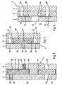
- Fig. 1 shows an embodiment of the sensor card 2 according to the invention in the plan view, the structure of the sensor card 2 for reasons of clarity on hand of Fig. 2 will be explained in more detail.
- the sensor card 2 has a sensor film 4 and a cover film 6, wherein the sensor film 4 (not shown) faces in a measurement of the liquid sample to be analyzed, whereas the cover film 6 is remote from the liquid sample. Between the sensor film 4 and the cover sheet 6, an intermediate film 8 is arranged.
- the films 4, 6, 8 is in the present embodiment to polyester films having a thickness between 80 and 120 microns and are connected to each other flat.
- the sensor film 4 has a plurality of openings 10 to 24 arranged in a line. Furthermore, two spaced-apart elongated openings 26, 28 and a ventilation opening 29 are provided in the sensor film 4.
- the intermediate film 8 On the side of the sensor film 4 facing the intermediate film 8 there are also printed electrical conductors (shown in dashed lines), wherein in each case one printed conductor 30 is arranged above the openings 16 to 24 and one further printed conductor 32 is arranged underneath the openings 16, 18, 22 and 24 , In addition, a further conductor track 34 for a reference electrode is arranged above the opening 10.
- the intermediate film 8 has a plurality of recesses 36, 38, 40, 42 and 44. Further, an elongated recess 46 is provided. In the recesses 36, which are rectangular in the present embodiment, ion-selective sensors 48 are arranged, while in the recesses 38 gas sensors, namely an oxygen sensor 50 and a carbon dioxide sensor 52, are inserted. Within the circular recess 44, a ventilation membrane 54 is provided.
- two conductivity sensors 56 are further arranged, each having two electrically conductive and spaced apart line sections 58, 60 which are printed on the sensor film 4 side facing.
- an elongated line section 62 is further printed, which acts as a reference electrode.
- a plurality of openings 64, 66 for electrical tapping and a ventilation opening 68 are provided.
- the sensor card 2 is connected to a plate 74 ( Fig. 1a ), which forms a replaceable unit with other components within the analysis system or the measuring instrument.
- a plate 74 Fig. 1a
- positioning holes 79 are provided in the sensor card, engage by the pins which are provided on the plate.
- the sensor card 2 is connected to the plate 74 such that the sensor film 4 rests on the plate.
- the plate 74 has at least one laterally open channel 76, which can be formed by a groove.
- a flow channel 78 is provided for the liquid sample, which is bounded by the wall of the channel 76 of the plate 76 on the one hand and the inside of the sensor film 4 on the other.
- the flow channel 78 leads along the openings 10 to 24 in the sensor film 4 arranged in a line, so that the liquid or gas sample can come into contact with the sensors 48, 50, 52, 56 located behind it.
- the two separate and spaced elongated openings 26 and 28 in the sensor film 4 are in fluid communication with a portion of the elongate recess 46 in the intermediate film 8, so that liquids or gases, for example, reagent solution as the inner electrolyte of the reference electrode of the ion-selective sensors or possibly Sample liquid from one opening 26 or 28 through the elongated recess 46 to the other opening 28 and 26 can flow.
- the two elongate openings 26, 28 each extend transversely, preferably at right angles to the elongated recess 46 in the intermediate foil 8, as shown in FIG Fig. 1 is shown.
- the sensor film 4 is deep-drawn, while in the intermediate film 8 and the cover sheet 6 openings 82 are provided. This ensures that the actuators acting on these areas of the sensor card do not exert any pressure on the sensor card exercise as long as they are not operated.
- Fig. 3 1 shows the ion-selective sensor 48 arranged between the sensor film 4 and the cover film 6, which consists of a carrier material 48 'which is activated or functionalized in the region of the opening 12 with an ion-selective reagent mixture (cocktail) 48 "The ion-selective cocktail fills the opening completely off and seals the sensor against the sensor film.
- a carrier material 48 ' which is activated or functionalized in the region of the opening 12 with an ion-selective reagent mixture (cocktail) 48
- ion-selective cocktail fills the opening completely off and seals the sensor against the sensor film.
- the carrier material 48 'of the ion-selective sensor 48 is disposed within the recess 36 in the intermediate film 8, so that the sensor card 2 in the region of the ion-selective sensor 48 is not thicker than in other areas in which no sensor is provided.
- the thickness of the intermediate foil 8 corresponds to the thickness of the carrier material of the sensor.
- the sensor card thus has the advantage that it has a homogeneous thickness.
- a sensor card 2 which has just been formed in this way can be attached in a particularly simple and secure manner to the plate with grooves, with which the sensor card 2 forms the flow channels, so that a high density of the flow channels is ensured.
- the ventilation membrane 54 which also in Fig. 3 is shown.
- the ion-selective sensor 48 can be electrically tapped via the opening 48 in the cover film 6 assigned to the sensor 48, in order to forward corresponding signals to the analysis unit, not shown, of the analysis system.
- the ion-selective sensor 48 has on its side facing the opening 66 for electrical tapping on a conductive coating 70, which simplifies the electrical tap.
- the ion-selective sensor 48 in the region of the opening 12 in the sensor film 4 with the liquid sample (not shown) can be wetted.
- the opening 12 in the sensor film 4 and the opening 66 are disposed offset from each other for electrical tapping.
- the electrical tap opening 66 like the other openings 64, 66 in the cover sheet, is filled with a cured electrically conductive paste 67, namely carbon paste, which facilitates picking and makes it safer.
- the paste 67 was merely in contact with the opening 66 in FIG Fig. 3 indicated by way of example.
- the ventilation membrane 54 Down in Fig. 3 the ventilation membrane 54 is shown, which rests in the recess 44 in the intermediate foil 8.
- the ventilation diaphragm 54 adjoins the ventilation opening 29 on the sensor film side and the ventilation opening 68 on the cover film side. Since the ventilation opening 68 serves the ventilation and not the electrical tap, this is not filled with carbon paste.
- the ventilation diaphragm 54 like all sensors, is larger than its associated opening 29, so that it rests securely in the recess 44 in the intermediate foil 8.
- the carrier material 52 'of the carbon dioxide sensor 52 is disposed within the recess 38 in the intermediate film 8, so that with respect to the thickness of the entire sensor card 2 also with reference on Fig. 3 described benefits occur.
- the carbon dioxide sensor 52 is in contact, on the one hand, with the first printed conductor 30 on the sensor film 4 and, on the other hand, with the second printed conductor 32 on the sensor film 4.
- the conductor track 30 can be tapped off electrically via the opening 64 in the cover film 6 and the recess 40 in the intermediate film 8, while the electrical tap of the conductor track 32 can take place via the opening 66 in the cover film 6 and the recess 42 in the intermediate film 8. This is also referred to as a via.
- the recesses 40 and 42 are filled with carbon paste, which is not shown for reasons above.
- the carrier material 52 'of the carbon dioxide sensor 52 has a coating facing the sensor film 4, preferably an imprint of silver / silver chloride and a pH-sensitive material. As activation or functionalization, an inner electrolyte 52 "and the gas-permeable membrane 52" are applied to the coating. The inner electrolyte 52 "and the gas-permeable membrane 52" fill the opening 18 in the sensor film 4.
- the carbon dioxide sensor 52 can come into contact with the sample through the opening 18 in the sensor foil 4 on its side facing the sensor foil 4.
- Fig. 5 shows the conductivity sensor 56 ( Fig. 2 ) in cross section.
- the conductivity sensor 56 is not formed as a sensor inlay, but rather consists of the above-described line sections 58 and 60, which are printed on the sensor film 4 facing side of the intermediate film 8.
- the one line section 58 is in contact with a first printed conductor 30, which is located on the sensor film 4, while the other line section 60 contacts a second printed conductor 32 located on the sensor film 4.
- the first interconnect 30 can be electrically tapped via the opening 64 in the cover film 6 and the recess 40 in the intermediate film 8, while the electrical tap of the second interconnect 32 via the opening 66 in the cover film 6 and the recess 42 in the intermediate film 8 can.
- the recesses 40 and 42 are filled with unillustrated carbon paste.
- Both line sections 58, 60 extend behind the opening 24 within the sensor film 4 and can thus be wetted via this opening 24 with the liquid sample. By entering into the opening 24 liquid, the two line sections 58, 60 are electrically connected, so that the conductivity of the liquid sample can be determined.
- the in Fig. 2 represented films, namely the sensor film 4, the cover sheet 6 and the intermediate foil 8 provided and arranged in the manner shown.
- the superimposed films 4, 6, 8 are connected to each other surface, wherein the bonding can be done by gluing, hot lamination, heat welding or high frequency welding.
- the insertion of the sensors is particularly simple when the foils 4, 6, 8 are already partially connected to one another before the insertion of the sensor inlays, for example by the lower edge 72 (FIG. Fig. 2 ) of the films 4, 6, 8 is laminated.
- the sensors are activated or functionalized only after connecting the films.
- the various analyte-specific reagent solutions for activating or functionalizing the sensors are applied to the carrier materials of the respective sensors through the openings in the sensor film and dried.
Claims (22)
- Carte sensorielle destinée à déterminer les substances à analyser dans des échantillons de liquide ou de gaz, munie de feuilles reliées entre elles de manière plane, comportant✔ une feuille sensorielle (4), orientée vers l'échantillon et munie d'orifices (10-24, 26, 28, 29),✔ une feuille de recouvrement (6) détournée de l'échantillon, et✔ au moins un capteur ou une partie d'un capteur (48, 50, 52), qui est disposé entre la feuille sen-sorielle (4) et la feuille de recouvrement (6),✔ au moins une feuille intermédiaire (8) avec des évidements (36, 38, 40, 42, 44, 46) étant pré-vue entre la feuille sensorielle (4) et la feuille de recouvrement (6), et le capteur (48, 50, 52) étant logé dans l'un des évidements (36, 38),caractérisée en ce que la feuille de recouvrement (6), détournée de l'échantillon, est munie d'ori-fices (64, 66) pour le branchement électrique dudit au moins un capteur (48, 50, 52).
- Carte sensorielle selon la revendication 1, caractérisée en ce que l'épaisseur de la feuille intermédiaire (8) est supérieure ou égale à l'épaisseur du capteur ou de la partie du capteur (48, 50, 52).
- Carte sensorielle selon la revendication 1 ou 2, caractérisée en ce que les orifices (64, 66) pour le branchement électrique sont remplis d'une pâte (67) électroconductrice durcie.
- Carte sensorielle selon l'une quelconque des revendications précédentes, caractérisée en ce que le capteur est un capteur ionosensible (48) qui, d'une part, peut être branché électriquement via un des orifices (66) dans la feuille de recouvrement (6) et, d'autre part, peut entrer en contact avec l'échantillon de liquide ou de gaz via les orifices (10, 12, 14, 20) dans la feuille sensorielle (4).
- Carte sensorielle selon la revendication 4, caractérisée en ce que l'orifice (66) pour le branchement électrique dans la feuille de recouvrement (6) est décalé par rapport à l'orifice (10, 12, 14, 20) dans la feuille sensorielle (4).
- Carte sensorielle selon la revendication 4 ou 5, caractérisée en ce que le capteur ionosensible (48) comporte un matériau de base (48') inséré dans l'évidement (36), lequel est activé avec un mélange réactif (48") ionosensible dans la zone de l'orifice (10, 12, 14, 20) dans la feuille sensorielle (4).
- Carte sensorielle selon la revendication 6, caractérisée en ce que le matériau de base com-porte un revêtement conducteur (70) sur sa face orientée vers l'orifice (66) pour le branchement électrique.
- Carte sensorielle selon l'une quelconque des revendication précédentes, caractérisée en ce que la feuille sensorielle (4) comporte des pistes conductrices (30, 32, 34) électriques imprimées, orientées vers la feuille intermédiaire (8), lesdites pistes conductrices (30, 32, 34) pouvant être branchées électriquement via les orifices (64, 66) pour le branchement électrique et au moins un des évidements (40, 42) dans la feuille intermédiaire (8).
- Carte sensorielle selon la revendication 8, caractérisé en ce que le capteur est un capteur de gaz, qui est en contact avec une première piste conductrice (30) et une deuxième piste con-ductrice (32) sur la feuille sensorielle (4) et qui peut entrer en contact avec l'échantillon de liquide ou de gaz via l'un des orifices (18, 22) dans la feuille sensorielle (4).
- Carte sensorielle selon la revendication 9, caractérisée en ce que le capteur de gaz est un capteur de dioxyde de carbone (52), en particu-lier un capteur de dioxyde de carbone qui est muni d'un matériau de base (52'), qui comporte un revêtement orienté vers la feuille sensorielle (4), de préférence une impression avec un maté-riau à base d'argent ou de chlorure d'argent et un matériau sensible au pH, un électrolyte interne (52") et une membrane (52") perméable au gaz étant déposés sur le revêtement pour réaliser une activation.
- Carte sensorielle selon la revendication 9, caractérisée en ce que le capteur de gaz est un capteur d'oxygène (50), en particulier un capteur d'oxygène qui est muni d'un matériau de base, sur lequel sont déposées, de préférence imprimées, des couches d'un matériau approprié à former une électrode de travail et d'un matériau approprié à former une électrode de référence, un électrolyte interne et une membrane perméable au gaz étant déposés sur les couches pour réaliser une acti-vation.
- Carte sensorielle selon la revendication 8, caractérisée en ce que le capteur est un capteur conducteur (56), qui comporte deux tronçons d'interconnexion (58, 60) électroconducteurs, qui sont situés à distance l'un de l'autre et qui sont imprimés sur la face de la feuille inter-médiaire (8), orientée
vers la feuille senso-rielle (4), l'un des tronçons d'interconnexion (58) étant en contact avec une première piste conductrice (30) sur la feuille sensorielle (4), et l'autre tronçon d'interconnexion (60) étant en contact avec une deuxième piste conductrice (32) sur la feuille sensorielle (4), et les deux tronçons d'interconnexion (58, 60) étant aptes à être mouillés par l'échantillon de liquide et étant aptes à être reliés entre eux de manière électroconductrice via un orifice (16, 24) à l'intérieur de la feuille sensorielle (4). - Carte sensorielle selon l'une quelconque des revendications précédentes, caractérisée en ce qu'une membrane d'aération (54) est disposée dans au moins un des évidements (44) dans la feuille intermédiaire (8), ladite membrane d'aération (54) étant adjacente, d'une part, à un orifice d'aération (29) dans la feuille sensorielle (4) et, d'autre part, à un orifice d'aération (68) dans la feuille de recouvrement (6).
- Carte sensorielle selon l'une quelconque des revendications précédentes, caractérisée en ce que l'un des évidements (46) dans la feuille intermédiaire (8) a une forme allongée, ledit évidement (46) allongé étant en liaison fluidique avec au moins deux orifices (26, 28) séparés dans la feuille sensorielle (4).
- Carte sensorielle selon la revendication 14, caractérisée en ce que les deux orifices (26, 28) séparés ont une forme allongée et s'étendent transversalement, de préférence à angle droit, par rapport à l'évidement (46) allongé dans la feuille intermédiaire (8).
- Agencement destiné à déterminer les subs-tances à analyser dans des échantillons de liquide ou de gaz, comportant :✔ une carte sensorielle selon l'une des revendications précédentes,✔ une plaquette avec au moins un conduit ouvert latéralement,dans lequel la feuille sensorielle de la carte sensorielle est fixée sur la plaquette moyennant la formation d'un conduit d'écoulement fermé latéralement pour l'échantillon.
- Procédé pour la réalisation d'une carte sensorielle destinée à déterminer les substances à analyser dans des échantillons de liquide, munie de feuilles reliées entre elles de manière plane, comportant les étapes :✔ mise à disposition d'une feuille sensorielle avec des orifices, d'une feuille de recouvre-ment avec des orifices pour le branchement électrique et au moins d'une feuille intermé-diaire, dans laquelle sont prévus des évide-ments,✔ mise en place d'au moins un capteur ou d'une partie d'un capteur dans l'un des évidements dans la feuille intermédiaire, et✔ assemblage plan des feuilles superposées, la feuille intermédiaire étant disposée entre la feuille sensorielle et la feuille de recouvre-ment.
- Procédé selon la revendication 17, caracté-risé en ce qu'au moins une des feuilles est assemblée en partie de manière plane avec la feuille intermédiaire avant la mise en place du capteur ou de la partie du capteur dans l'un des évidements.
- procédé selon la revendication 18, caracté-risé en ce que la feuille sensorielle, de même que la feuille de recouvrement sont assemblées en partie de manière plane avec la feuille intermédiaire avant la mise en place du capteur de la partie du capteur dans l'un des évidements.
- Procédé selon l'une quelconque des revendica-tions 17 à 19, caractérise en ce qu'avant la mise à disposition de la feuille sensorielle, des pistes conductrices sont imprimées, de préférence par sérigraphie, sur la face de la feuille sensorielle orientée vers la feuille intermé-diaire.
- Procédé selon l'une quelconque des revendica-tions 17 à 20, caractérisé en ce qu'avant la mise à disposition de la feuille intermédiaire, des tronçons d'interconnexion sont imprimés, de préférence par sérigraphie, sur la face de la feuille intermédiaire, orientée vers la feuille sensorielle.
- Procédé selon l'une quelconque des revendica-tions 17 à 22, caractérisé en ce que l'assemblage est effectué par collage, laminage à chaud, soudage à chaud ou soudage à haute fréquence.
Applications Claiming Priority (2)
| Application Number | Priority Date | Filing Date | Title |
|---|---|---|---|
| DE10353938 | 2003-11-18 | ||
| DE10353938A DE10353938A1 (de) | 2003-11-18 | 2003-11-18 | Sensorkarte zur Bestimmung von Analyten in Flüssigkeits- oder Gasproben und Verfahren zur Herstellung einer solchen Sensorkarte |
Publications (2)
| Publication Number | Publication Date |
|---|---|
| EP1533614A1 EP1533614A1 (fr) | 2005-05-25 |
| EP1533614B1 true EP1533614B1 (fr) | 2011-09-21 |
Family
ID=34428790
Family Applications (1)
| Application Number | Title | Priority Date | Filing Date |
|---|---|---|---|
| EP04026357A Not-in-force EP1533614B1 (fr) | 2003-11-18 | 2004-11-05 | Carte test pour la détermination de substances dans un échantillon liquide ou gazeux et sa procédé de production |
Country Status (8)
| Country | Link |
|---|---|
| US (1) | US7837845B2 (fr) |
| EP (1) | EP1533614B1 (fr) |
| JP (1) | JP4594044B2 (fr) |
| KR (1) | KR101056126B1 (fr) |
| CN (1) | CN100580442C (fr) |
| AT (1) | ATE525646T1 (fr) |
| DE (1) | DE10353938A1 (fr) |
| ES (1) | ES2373951T3 (fr) |
Families Citing this family (15)
| Publication number | Priority date | Publication date | Assignee | Title |
|---|---|---|---|---|
| EP2102658B1 (fr) * | 2007-01-19 | 2019-05-15 | Circassia Ab | Dispositif et procédé d'analyse pour detecter un oxyde d'azote dans une phase gazeuse |
| EP1986007A1 (fr) * | 2007-04-27 | 2008-10-29 | Radiometer Medical ApS | Ensemble de capteurs pour des fluides de corps |
| DE202008009938U1 (de) | 2008-07-23 | 2008-10-09 | Bürkert Werke GmbH & Co.KG | Sensorsystem |
| KR101077919B1 (ko) | 2010-03-16 | 2011-10-31 | 대윤계기산업 주식회사 | 카드형 멀티측정기 |
| US8933292B2 (en) | 2011-10-28 | 2015-01-13 | Kimberly-Clark Worldwide, Inc. | Absorbent article with sensor array for body exudate detection |
| US9119748B2 (en) * | 2011-10-28 | 2015-09-01 | Kimberly-Clark Worldwide, Inc. | Electronic discriminating device for body exudate detection |
| US8816149B2 (en) | 2011-10-28 | 2014-08-26 | Kimberly-Clark Worldwide, Inc. | System for detection and monitoring of body exudates using a gas emitting substance for use in interactive toilet training |
| DE102011056273B4 (de) | 2011-12-12 | 2013-11-21 | sense2care GmbH | Fluidreservoir für eine Vorrichtung zur Analyse von Patientenproben |
| DE102011056271A1 (de) | 2011-12-12 | 2013-06-13 | sense2care GmbH | Vorrichtung zur Analyse von Patientenproben |
| DE102016210303A1 (de) * | 2016-06-10 | 2017-12-14 | Airbus Defence and Space GmbH | Sensorträgerfolie für ein Objekt und Verfahren zum Bestücken eines Objekts mit einer Sensorik |
| DE102016117441A1 (de) * | 2016-09-16 | 2018-03-22 | Dr. Ing. H.C. F. Porsche Aktiengesellschaft | Traktionsbatterie und Fahrzeug mit einer solchen |
| DE102016118526A1 (de) | 2016-09-29 | 2018-03-29 | Krohne Messtechnik Gmbh | Leitfähigkeitsmessgerät zur Messung einer elektrischen Leitfähigkeit eines flüssigen Mediums |
| EP3805755A1 (fr) | 2016-12-23 | 2021-04-14 | Radiometer Medical ApS | Ensemble capteur pour liquides corporels |
| CN107390519B (zh) * | 2017-06-22 | 2020-01-07 | 西安交通大学 | 一种直流电缆材料配方的筛选方法 |
| CN115406946B (zh) * | 2022-08-16 | 2023-06-30 | 山东卓越生物技术股份有限公司 | 一次性即时检测卡片及传感器芯片的po2电极制备方法 |
Family Cites Families (27)
| Publication number | Priority date | Publication date | Assignee | Title |
|---|---|---|---|---|
| US4225410A (en) * | 1978-12-04 | 1980-09-30 | Technicon Instruments Corporation | Integrated array of electrochemical sensors |
| US4454007A (en) * | 1983-01-27 | 1984-06-12 | E. I. Du Pont De Nemours And Company | Ion-selective layered sensor and methods of making and using the same |
| JPH0612350B2 (ja) * | 1985-06-26 | 1994-02-16 | 株式会社東芝 | 流通型イオンセンサ体 |
| JPS63151845A (ja) * | 1986-12-16 | 1988-06-24 | Fuji Photo Film Co Ltd | イオン活量測定器具 |
| DE3810186A1 (de) * | 1987-08-01 | 1989-10-05 | Siegert Gmbh | Sensor zur messung der aktivitaet von ionen, sowie verfahren zu dessen herstellung |
| US5405510A (en) * | 1992-05-18 | 1995-04-11 | Ppg Industries, Inc. | Portable analyte measuring system for multiple fluid samples |
| FR2701117B1 (fr) | 1993-02-04 | 1995-03-10 | Asulab Sa | Système de mesures électrochimiques à capteur multizones, et son application au dosage du glucose. |
| US5700360A (en) * | 1995-10-31 | 1997-12-23 | Chiron Diagnostics Corporation | Fluoroelastomer gasket for blood sensors |
| US5858452A (en) * | 1996-05-16 | 1999-01-12 | Sendx Medical, Inc. | Method for fabricating wiring substrate with subminiature thru-holes |
| US6080668A (en) * | 1996-05-30 | 2000-06-27 | International Business Machines Corporation | Sequential build-up organic chip carrier and method of manufacture |
| DE19631530C2 (de) * | 1996-07-23 | 2000-03-09 | Inst Chemo Biosensorik | Ionenselektiver Sensor |
| US5830337A (en) * | 1996-07-24 | 1998-11-03 | Gastech, Inc. | Electrochemical gas sensor |
| DE19747875A1 (de) | 1997-10-20 | 1999-05-06 | Meinhard Prof Dr Knoll | Verfahren zum Messen veränderlicher Größen und Vorrichtung zum Durchführen des Verfahrens |
| JP3350810B2 (ja) * | 1997-12-29 | 2002-11-25 | 太陽誘電株式会社 | イオンセンサ及びイオンセンサプレート |
| JPH11281757A (ja) * | 1998-03-30 | 1999-10-15 | Fujitsu Ltd | 大気汚染物質測定システム |
| US6123820A (en) * | 1998-06-05 | 2000-09-26 | Grupo Ch-Werfen, S.A. | Sensor cartridges |
| US6287451B1 (en) * | 1999-06-02 | 2001-09-11 | Handani Winarta | Disposable sensor and method of making |
| DE19929264A1 (de) * | 1999-06-25 | 2001-01-11 | Meinhard Knoll | Universaltransducer |
| JP2003527972A (ja) * | 1999-10-04 | 2003-09-24 | ナノストリーム・インコーポレイテッド | 挟まれたステンシルを含むモジュラー型マイクロ流体デバイス |
| US20030057108A1 (en) * | 1999-12-10 | 2003-03-27 | Ramamurthi Sridharan | Device and method for accelerated hydration of dry chemical sensors |
| DE10003507B4 (de) * | 2000-01-27 | 2004-06-03 | Knoll, Meinhard, Prof. Dr. | Vorrichtung und Verfahren zur Entnahme von Flüssigkeiten aus körpereigenem Gewebe und Bestimmung von Stoffkonzentrationen in dieser Flüssigkeit |
| KR100446468B1 (ko) * | 2001-05-18 | 2004-09-01 | 주식회사 아이센스 | 시료도입의 능력을 향상시킨 크로마토그래피 기능의다공성 박막이 구비된 바이오센서 |
| US6572745B2 (en) * | 2001-03-23 | 2003-06-03 | Virotek, L.L.C. | Electrochemical sensor and method thereof |
| US6652720B1 (en) * | 2001-05-31 | 2003-11-25 | Instrumentation Laboratory Company | Analytical instruments, biosensors and methods thereof |
| US6960466B2 (en) * | 2001-05-31 | 2005-11-01 | Instrumentation Laboratory Company | Composite membrane containing a cross-linked enzyme matrix for a biosensor |
| US6872297B2 (en) * | 2001-05-31 | 2005-03-29 | Instrumentation Laboratory Company | Analytical instruments, biosensors and methods thereof |
| GB0123416D0 (en) * | 2001-09-28 | 2001-11-21 | Memquest Ltd | Non-volatile memory control |
-
2003
- 2003-11-18 DE DE10353938A patent/DE10353938A1/de not_active Withdrawn
-
2004
- 2004-11-05 ES ES04026357T patent/ES2373951T3/es active Active
- 2004-11-05 EP EP04026357A patent/EP1533614B1/fr not_active Not-in-force
- 2004-11-05 AT AT04026357T patent/ATE525646T1/de active
- 2004-11-17 US US10/992,193 patent/US7837845B2/en not_active Expired - Fee Related
- 2004-11-18 CN CN200410094794A patent/CN100580442C/zh not_active Expired - Fee Related
- 2004-11-18 JP JP2004333878A patent/JP4594044B2/ja not_active Expired - Fee Related
- 2004-11-18 KR KR1020040094498A patent/KR101056126B1/ko not_active IP Right Cessation
Also Published As
| Publication number | Publication date |
|---|---|
| ATE525646T1 (de) | 2011-10-15 |
| KR101056126B1 (ko) | 2011-08-11 |
| CN1624468A (zh) | 2005-06-08 |
| US20090321258A1 (en) | 2009-12-31 |
| JP2005148077A (ja) | 2005-06-09 |
| ES2373951T3 (es) | 2012-02-10 |
| JP4594044B2 (ja) | 2010-12-08 |
| US7837845B2 (en) | 2010-11-23 |
| CN100580442C (zh) | 2010-01-13 |
| EP1533614A1 (fr) | 2005-05-25 |
| KR20050048513A (ko) | 2005-05-24 |
| DE10353938A1 (de) | 2005-06-23 |
Similar Documents
| Publication | Publication Date | Title |
|---|---|---|
| DE60122517T2 (de) | Elektrisch leitfähige muster zur überwachung der befüllung medizinischer geräte | |
| EP1533614B1 (fr) | Carte test pour la détermination de substances dans un échantillon liquide ou gazeux et sa procédé de production | |
| DE60225723T2 (de) | Mikrobandelektrode | |
| EP1977225B1 (fr) | Système d analyse à biocapteur électrochimique | |
| DE60122588T2 (de) | Elektrochemische teststreifenkarten die ein eingebautes trockenmittel enthalten | |
| DE60020076T2 (de) | Kleinvolumiger in-vitro-analyt-sensor | |
| DE60025334T2 (de) | Wegwerfteststreifen mit einer intgrierten reagenz/blut trennschicht | |
| DE60035981T2 (de) | Elektrochemischer biosensor-teststreifen, verfahren zur herstellung und elektrochemischer biosensor | |
| DE60012946T2 (de) | Interferenzreduzierter wegwerfbarer sensor und herstellungsverfahren | |
| DE19822123C2 (de) | Verfahren und Vorrichtung zum Nachweis von Analyten | |
| DE602004006148T2 (de) | Verfahren zur reduzierung des effekts eines direkten interferenzstroms in einem elektrochemischen teststreifen | |
| DE102010002915B4 (de) | Mikrofluidischer Sensor | |
| EP1542803A1 (fr) | Systeme d'analyse a capteurs capillaires multiples | |
| DE112018005405B4 (de) | REGELUNG DES pH-WERTES ZUM DETEKTIEREN VON ANALYTEN | |
| DE19848112C2 (de) | Minimalinvasives Sensorsystem | |
| DE19546535C2 (de) | Meßkartusche für flüssige oder gasförmige Proben, Verfahren zu deren Betreiben und deren Verwendung | |
| DE2127142A1 (de) | Analysiergerät | |
| DE102005017364B4 (de) | Analysegerät mit auswechselbarem Testfeldträger | |
| DE202015101592U1 (de) | Elektrochemisches Biosensormessgerät und System zur Analytmessung mit Probenfülldetektion | |
| EP1393807B1 (fr) | Dispositif d' essai pour l'analyse d' un échantillon biologique fluide | |
| WO1999020999A1 (fr) | Procede de mesure de grandeurs variables, et dispositif pour la mise en oeuvre de ce procede | |
| DE10234564A1 (de) | Biosensor | |
| DE102017121914A1 (de) | Sensorelement und Verfahren zum Herstellen eines Sensorelements | |
| EP3646029B1 (fr) | Système de détection et procédé pour sa fabrication | |
| AT520605B1 (de) | Sensorkassette |
Legal Events
| Date | Code | Title | Description |
|---|---|---|---|
| PUAI | Public reference made under article 153(3) epc to a published international application that has entered the european phase |
Free format text: ORIGINAL CODE: 0009012 |
|
| AK | Designated contracting states |
Kind code of ref document: A1 Designated state(s): AT BE BG CH CY CZ DE DK EE ES FI FR GB GR HU IE IS IT LI LU MC NL PL PT RO SE SI SK TR |
|
| AX | Request for extension of the european patent |
Extension state: AL HR LT LV MK YU |
|
| 17P | Request for examination filed |
Effective date: 20050428 |
|
| RIN1 | Information on inventor provided before grant (corrected) |
Inventor name: SCHROERS, ALEXANDER Inventor name: MAGER, GERHARD, DR. Inventor name: HAECKER, JUERGEN Inventor name: CHEMNITIUS, GABRIELE, DR. Inventor name: ABEL, PETRA |
|
| AKX | Designation fees paid |
Designated state(s): AT BE BG CH CY CZ DE DK EE ES FI FR GB GR HU IE IS IT LI LU MC NL PL PT RO SE SI SK TR |
|
| 17Q | First examination report despatched |
Effective date: 20071220 |
|
| GRAP | Despatch of communication of intention to grant a patent |
Free format text: ORIGINAL CODE: EPIDOSNIGR1 |
|
| GRAS | Grant fee paid |
Free format text: ORIGINAL CODE: EPIDOSNIGR3 |
|
| GRAA | (expected) grant |
Free format text: ORIGINAL CODE: 0009210 |
|
| AK | Designated contracting states |
Kind code of ref document: B1 Designated state(s): AT BE BG CH CY CZ DE DK EE ES FI FR GB GR HU IE IS IT LI LU MC NL PL PT RO SE SI SK TR |
|
| REG | Reference to a national code |
Ref country code: GB Ref legal event code: FG4D Free format text: NOT ENGLISH |
|
| REG | Reference to a national code |
Ref country code: CH Ref legal event code: EP |
|
| REG | Reference to a national code |
Ref country code: IE Ref legal event code: FG4D Free format text: LANGUAGE OF EP DOCUMENT: GERMAN |
|
| REG | Reference to a national code |
Ref country code: DE Ref legal event code: R096 Ref document number: 502004012876 Country of ref document: DE Effective date: 20111117 |
|
| REG | Reference to a national code |
Ref country code: NL Ref legal event code: VDEP Effective date: 20110921 |
|
| PG25 | Lapsed in a contracting state [announced via postgrant information from national office to epo] |
Ref country code: SE Free format text: LAPSE BECAUSE OF FAILURE TO SUBMIT A TRANSLATION OF THE DESCRIPTION OR TO PAY THE FEE WITHIN THE PRESCRIBED TIME-LIMIT Effective date: 20110921 Ref country code: FI Free format text: LAPSE BECAUSE OF FAILURE TO SUBMIT A TRANSLATION OF THE DESCRIPTION OR TO PAY THE FEE WITHIN THE PRESCRIBED TIME-LIMIT Effective date: 20110921 |
|
| REG | Reference to a national code |
Ref country code: ES Ref legal event code: FG2A Ref document number: 2373951 Country of ref document: ES Kind code of ref document: T3 Effective date: 20120210 |
|
| PG25 | Lapsed in a contracting state [announced via postgrant information from national office to epo] |
Ref country code: GR Free format text: LAPSE BECAUSE OF FAILURE TO SUBMIT A TRANSLATION OF THE DESCRIPTION OR TO PAY THE FEE WITHIN THE PRESCRIBED TIME-LIMIT Effective date: 20111222 Ref country code: CY Free format text: LAPSE BECAUSE OF FAILURE TO SUBMIT A TRANSLATION OF THE DESCRIPTION OR TO PAY THE FEE WITHIN THE PRESCRIBED TIME-LIMIT Effective date: 20110921 Ref country code: SI Free format text: LAPSE BECAUSE OF FAILURE TO SUBMIT A TRANSLATION OF THE DESCRIPTION OR TO PAY THE FEE WITHIN THE PRESCRIBED TIME-LIMIT Effective date: 20110921 |
|
| REG | Reference to a national code |
Ref country code: IE Ref legal event code: FD4D |
|
| PG25 | Lapsed in a contracting state [announced via postgrant information from national office to epo] |
Ref country code: IS Free format text: LAPSE BECAUSE OF FAILURE TO SUBMIT A TRANSLATION OF THE DESCRIPTION OR TO PAY THE FEE WITHIN THE PRESCRIBED TIME-LIMIT Effective date: 20120121 Ref country code: CZ Free format text: LAPSE BECAUSE OF FAILURE TO SUBMIT A TRANSLATION OF THE DESCRIPTION OR TO PAY THE FEE WITHIN THE PRESCRIBED TIME-LIMIT Effective date: 20110921 Ref country code: SK Free format text: LAPSE BECAUSE OF FAILURE TO SUBMIT A TRANSLATION OF THE DESCRIPTION OR TO PAY THE FEE WITHIN THE PRESCRIBED TIME-LIMIT Effective date: 20110921 Ref country code: IE Free format text: LAPSE BECAUSE OF FAILURE TO SUBMIT A TRANSLATION OF THE DESCRIPTION OR TO PAY THE FEE WITHIN THE PRESCRIBED TIME-LIMIT Effective date: 20110921 |
|
| BERE | Be: lapsed |
Owner name: FRESENIUS MEDICAL CARE DEUTSCHLAND G.M.B.H. Effective date: 20111130 |
|
| PG25 | Lapsed in a contracting state [announced via postgrant information from national office to epo] |
Ref country code: PL Free format text: LAPSE BECAUSE OF FAILURE TO SUBMIT A TRANSLATION OF THE DESCRIPTION OR TO PAY THE FEE WITHIN THE PRESCRIBED TIME-LIMIT Effective date: 20110921 Ref country code: NL Free format text: LAPSE BECAUSE OF FAILURE TO SUBMIT A TRANSLATION OF THE DESCRIPTION OR TO PAY THE FEE WITHIN THE PRESCRIBED TIME-LIMIT Effective date: 20110921 Ref country code: RO Free format text: LAPSE BECAUSE OF FAILURE TO SUBMIT A TRANSLATION OF THE DESCRIPTION OR TO PAY THE FEE WITHIN THE PRESCRIBED TIME-LIMIT Effective date: 20110921 Ref country code: PT Free format text: LAPSE BECAUSE OF FAILURE TO SUBMIT A TRANSLATION OF THE DESCRIPTION OR TO PAY THE FEE WITHIN THE PRESCRIBED TIME-LIMIT Effective date: 20120123 Ref country code: EE Free format text: LAPSE BECAUSE OF FAILURE TO SUBMIT A TRANSLATION OF THE DESCRIPTION OR TO PAY THE FEE WITHIN THE PRESCRIBED TIME-LIMIT Effective date: 20110921 |
|
| PG25 | Lapsed in a contracting state [announced via postgrant information from national office to epo] |
Ref country code: MC Free format text: LAPSE BECAUSE OF NON-PAYMENT OF DUE FEES Effective date: 20111130 |
|
| REG | Reference to a national code |
Ref country code: CH Ref legal event code: PL |
|
| PLBE | No opposition filed within time limit |
Free format text: ORIGINAL CODE: 0009261 |
|
| STAA | Information on the status of an ep patent application or granted ep patent |
Free format text: STATUS: NO OPPOSITION FILED WITHIN TIME LIMIT |
|
| PG25 | Lapsed in a contracting state [announced via postgrant information from national office to epo] |
Ref country code: CH Free format text: LAPSE BECAUSE OF NON-PAYMENT OF DUE FEES Effective date: 20111130 Ref country code: DK Free format text: LAPSE BECAUSE OF FAILURE TO SUBMIT A TRANSLATION OF THE DESCRIPTION OR TO PAY THE FEE WITHIN THE PRESCRIBED TIME-LIMIT Effective date: 20110921 Ref country code: LI Free format text: LAPSE BECAUSE OF NON-PAYMENT OF DUE FEES Effective date: 20111130 |
|
| 26N | No opposition filed |
Effective date: 20120622 |
|
| PG25 | Lapsed in a contracting state [announced via postgrant information from national office to epo] |
Ref country code: BE Free format text: LAPSE BECAUSE OF NON-PAYMENT OF DUE FEES Effective date: 20111130 |
|
| REG | Reference to a national code |
Ref country code: DE Ref legal event code: R097 Ref document number: 502004012876 Country of ref document: DE Effective date: 20120622 |
|
| REG | Reference to a national code |
Ref country code: AT Ref legal event code: MM01 Ref document number: 525646 Country of ref document: AT Kind code of ref document: T Effective date: 20111105 |
|
| PG25 | Lapsed in a contracting state [announced via postgrant information from national office to epo] |
Ref country code: AT Free format text: LAPSE BECAUSE OF NON-PAYMENT OF DUE FEES Effective date: 20111105 |
|
| PG25 | Lapsed in a contracting state [announced via postgrant information from national office to epo] |
Ref country code: LU Free format text: LAPSE BECAUSE OF NON-PAYMENT OF DUE FEES Effective date: 20111105 |
|
| PG25 | Lapsed in a contracting state [announced via postgrant information from national office to epo] |
Ref country code: BG Free format text: LAPSE BECAUSE OF FAILURE TO SUBMIT A TRANSLATION OF THE DESCRIPTION OR TO PAY THE FEE WITHIN THE PRESCRIBED TIME-LIMIT Effective date: 20111221 |
|
| PG25 | Lapsed in a contracting state [announced via postgrant information from national office to epo] |
Ref country code: TR Free format text: LAPSE BECAUSE OF FAILURE TO SUBMIT A TRANSLATION OF THE DESCRIPTION OR TO PAY THE FEE WITHIN THE PRESCRIBED TIME-LIMIT Effective date: 20110921 |
|
| PG25 | Lapsed in a contracting state [announced via postgrant information from national office to epo] |
Ref country code: HU Free format text: LAPSE BECAUSE OF FAILURE TO SUBMIT A TRANSLATION OF THE DESCRIPTION OR TO PAY THE FEE WITHIN THE PRESCRIBED TIME-LIMIT Effective date: 20110921 |
|
| PGFP | Annual fee paid to national office [announced via postgrant information from national office to epo] |
Ref country code: DE Payment date: 20131128 Year of fee payment: 10 Ref country code: GB Payment date: 20131127 Year of fee payment: 10 |
|
| PGFP | Annual fee paid to national office [announced via postgrant information from national office to epo] |
Ref country code: IT Payment date: 20131113 Year of fee payment: 10 Ref country code: FR Payment date: 20131128 Year of fee payment: 10 |
|
| PGFP | Annual fee paid to national office [announced via postgrant information from national office to epo] |
Ref country code: ES Payment date: 20131128 Year of fee payment: 10 |
|
| REG | Reference to a national code |
Ref country code: DE Ref legal event code: R119 Ref document number: 502004012876 Country of ref document: DE |
|
| GBPC | Gb: european patent ceased through non-payment of renewal fee |
Effective date: 20141105 |
|
| REG | Reference to a national code |
Ref country code: FR Ref legal event code: ST Effective date: 20150731 |
|
| PG25 | Lapsed in a contracting state [announced via postgrant information from national office to epo] |
Ref country code: GB Free format text: LAPSE BECAUSE OF NON-PAYMENT OF DUE FEES Effective date: 20141105 Ref country code: DE Free format text: LAPSE BECAUSE OF NON-PAYMENT OF DUE FEES Effective date: 20150602 |
|
| PG25 | Lapsed in a contracting state [announced via postgrant information from national office to epo] |
Ref country code: FR Free format text: LAPSE BECAUSE OF NON-PAYMENT OF DUE FEES Effective date: 20141201 |
|
| PG25 | Lapsed in a contracting state [announced via postgrant information from national office to epo] |
Ref country code: IT Free format text: LAPSE BECAUSE OF NON-PAYMENT OF DUE FEES Effective date: 20141105 |
|
| REG | Reference to a national code |
Ref country code: ES Ref legal event code: FD2A Effective date: 20160129 |
|
| PG25 | Lapsed in a contracting state [announced via postgrant information from national office to epo] |
Ref country code: ES Free format text: LAPSE BECAUSE OF NON-PAYMENT OF DUE FEES Effective date: 20141106 |