EP1533614B1 - Sensor card for determining analytes in liquid and gaseous samples and method for producing same - Google Patents
Sensor card for determining analytes in liquid and gaseous samples and method for producing same Download PDFInfo
- Publication number
- EP1533614B1 EP1533614B1 EP04026357A EP04026357A EP1533614B1 EP 1533614 B1 EP1533614 B1 EP 1533614B1 EP 04026357 A EP04026357 A EP 04026357A EP 04026357 A EP04026357 A EP 04026357A EP 1533614 B1 EP1533614 B1 EP 1533614B1
- Authority
- EP
- European Patent Office
- Prior art keywords
- sensor
- film
- openings
- card according
- intermediate film
- Prior art date
- Legal status (The legal status is an assumption and is not a legal conclusion. Google has not performed a legal analysis and makes no representation as to the accuracy of the status listed.)
- Not-in-force
Links
Images


Classifications
-
- G—PHYSICS
- G01—MEASURING; TESTING
- G01N—INVESTIGATING OR ANALYSING MATERIALS BY DETERMINING THEIR CHEMICAL OR PHYSICAL PROPERTIES
- G01N27/00—Investigating or analysing materials by the use of electric, electrochemical, or magnetic means
- G01N27/26—Investigating or analysing materials by the use of electric, electrochemical, or magnetic means by investigating electrochemical variables; by using electrolysis or electrophoresis
- G01N27/28—Electrolytic cell components
- G01N27/30—Electrodes, e.g. test electrodes; Half-cells
- G01N27/333—Ion-selective electrodes or membranes
-
- G—PHYSICS
- G01—MEASURING; TESTING
- G01N—INVESTIGATING OR ANALYSING MATERIALS BY DETERMINING THEIR CHEMICAL OR PHYSICAL PROPERTIES
- G01N33/00—Investigating or analysing materials by specific methods not covered by groups G01N1/00 - G01N31/00
- G01N33/48—Biological material, e.g. blood, urine; Haemocytometers
- G01N33/483—Physical analysis of biological material
- G01N33/487—Physical analysis of biological material of liquid biological material
- G01N33/49—Blood
- G01N33/492—Determining multiple analytes
-
- Y—GENERAL TAGGING OF NEW TECHNOLOGICAL DEVELOPMENTS; GENERAL TAGGING OF CROSS-SECTIONAL TECHNOLOGIES SPANNING OVER SEVERAL SECTIONS OF THE IPC; TECHNICAL SUBJECTS COVERED BY FORMER USPC CROSS-REFERENCE ART COLLECTIONS [XRACs] AND DIGESTS
- Y10—TECHNICAL SUBJECTS COVERED BY FORMER USPC
- Y10T—TECHNICAL SUBJECTS COVERED BY FORMER US CLASSIFICATION
- Y10T156/00—Adhesive bonding and miscellaneous chemical manufacture
- Y10T156/10—Methods of surface bonding and/or assembly therefor
Definitions
- the present invention relates to a sensor card for the determination of analytes in liquid or gas samples with surface-connected films. Furthermore, the invention relates to a method for producing such a sensor card.
- Such sensor cards are used in measuring instruments or analysis systems in which a liquid or gas sample is subjected to a chemical analysis, wherein the quantitative determination of different analytes in gaseous and liquid samples is possible.
- analysis systems are increasingly used in medical technology, process control and food and environmental analysis.
- the analysis of parameters of body fluids in the context of point-of-care (POC) testing in the field of medical diagnostics represents a major field of application of these analysis systems.
- POC point-of-care
- these blood parameters include the blood gases (pO 2 , pCO 2 , pH), the electrolytes (Na, K, Ca, Cl), the conductivity of the blood and derived therefrom the hematocrit and the metabolites (glucose, lactate, urea, creatinine).
- the location of the analysis is shifted from the central laboratory to the vicinity of the patient. The analyzes therefore no longer have to be carried out by specialized laboratory personnel, but can be carried out by the staff who also looks after the patient. This results in a considerable amount of time gained, which benefits a faster and more efficient treatment of the patient.
- Newer analyzers are increasingly using maintenance-free planar sensors, including: can be produced in large series using methods of thin and thick film technology.
- Several sensors each of which can specifically determine an analyte, are applied to a substrate.
- In the flow cell calibration solution and liquid sample are given via the sensors to determine the analyte concentrations.
- the known sensor cards with double-matrix membrane have a sensor film with openings, which faces the liquid sample to be examined in the position of use.
- a cover sheet is arranged, on which electrical conductor tracks of silver / silver chloride are printed, these conductor tracks facing the sensor film.
- Support materials for ion-selective DMM sensors are arranged between the sensor film and the cover film, which on the one hand adjoin an opening in the sensor film and, on the other hand, one of the conductor tracks on the cover film.
- the films and the sensors connected wherein the openings in the sensor film are formed smaller than the sensor surface, so that the edge of the opening depresses the edge of the sensor, which ultimately leads to an increase of the edge of the opening, the electrical tap is directly on the conductor tracks, which to extend this purpose to the edge of the cover sheet, which is formed larger than the sensor film, so that a part of the conductor is not covered by the sensor film and can be tapped.
- the known DMM sensor card is connected flat to a plate in which there are one or more grooves. This connection creates a flow channel for the liquid sample which is bounded on the one hand by the wall of the grooves and on the other hand by the sensor foil of the DMM sensor card.
- the openings in the sensor film in this case point to the flow channel, so that the sensors can be wetted with the fluid sample flowing through the flow channel.
- the known DMM Sensox card has the disadvantage that it does not ensure a reliable seal of the flow channels within the plate.
- the DE 197 47 875 A1 describes a sensor card that has a sensor foil, a cover foil and an intermediate foil.
- a sensor In a recess of the intermediate parts is a sensor.
- the electrical tap is made via contacts and contact strips, which led to contact lugs.
- the contacts, contact tracks and lugs are on the side of the cover sheet, which faces the intermediate film.
- the sensor comes into contact with the sample via an opening in the sensor film.
- the contacting of the sensor is disadvantageous insofar as contact paths and contact lugs are applied on the side of the cover film which faces the intermediate film. This creates the problem that the tabs can not be tapped easily.
- the problem is solved in that the cover film on the one hand and the intermediate and sensor film on the other hand are arranged one above the other so that the region of the cover film, on which the contact lugs are arranged, protrudes outward.
- the WO 02/097415 A2 describes an oxygen sensor having a working electrode, a reference electrode and a ground electrode.
- the working electrode has a platinum wire which sits in the center of a glass pane. On one side of the glass pane, the platinum wire is covered with two membranes, while the wire on the other side of the pane is contacted with an electrode. The platinum wire is exposed on the side facing away from the contact with the electrode, a gas stream, while the electrical tap on the side of contacting with the electrode takes place.
- the present invention is therefore based on the object to provide a sensor card for the determination of analytes in liquid samples, which ensures a secure seal of the flow channels for the liquid sample, and to provide a method for producing such a sensor card.
- the sensor card according to the invention for the determination of analytes in liquid or gas samples has two-dimensionally interconnected films.
- the film facing the liquid sample is referred to as a sensor film and is provided with openings.
- facing the liquid sample means that the sensor film with the fluid sample inside the Flow channels comes into contact, ie the sensor card is later, as already described with reference to the prior art, be connected flat with the plate in which the grooves are located.
- the sensor card also has a cover sheet facing away from the sample, ie, the cover sheet does not directly contact the sample. In the cover sheet openings for electrical tapping are also provided.
- the sensor card has at least one sensor which is arranged between the sensor film and the cover film.
- Suitable sensors are potentiometric, amperometric or conductometric analyzer-specific sensors.
- at least one intermediate foil is provided between the sensor foil and the cover foil.
- the intermediate foil recesses are provided, wherein the sensor is arranged in one of the recesses.
- the sensor card according to the invention has the advantage that it has a homogeneous thickness and a wavy shape is avoided. This is due to the fact that the increase, which inevitably arises due to the arrangement of the sensors between the sensor and cover film, is compensated for by the intermediate film in whose recesses the sensors are inserted. Such a newly formed sensor card can be attached to the plate with grooves in a particularly simple and secure manner, with which the sensor card forms the flow channels, so that a high density of the flow channels is ensured.
- the sensor card according to the invention has the advantages that it is very thin, can hold a large number of sensors and is inexpensive to produce.
- the thickness of the intermediate film is selected such that it corresponds to the thickness of the sensor or is larger.
- the first case an absolutely flat sensor card is created, while in the second case, smaller inwardly facing bulges may arise, which is still more advantageous in view of the tightness of the flow channels, as protruding bulges, as they occur in the known DMM sensor card.
- the openings are filled in a further preferred embodiment of the invention with a cured, electrically conductive paste.
- a cured, electrically conductive paste This may preferably be carbon paste.
- the senor is designed as an ion-selective sensor.
- the ion-selective sensor can be electrically tapped off via one of the openings in the cover film and, on the other hand, can be wetted with the liquid sample via one of the openings in the sensor film.
- the opening for the electrical tap of the ion-selective sensor is arranged in a further embodiment of the invention offset from the opening in the sensor film.
- offset here is to be understood that the opening in the cover sheet in the plan view of the sensor card and the opening in the sensor film are arranged at a distance from each other, preferably there is no overlap of the two openings.
- the ion-selective sensor has a carrier material lying in the recess.
- a carrier material is for example absorbent paper in question.
- the carrier material is activated or functionalized with an ion-selective reagent mixture. The reagent mixture completely fills the opening in the sensor film so that the ion-selective sensor is securely sealed against the sensor film.
- the carrier material of the ion-selective sensor has a conductive coating on its side facing the opening for electrical tapping.
- the conductive coating serves to electrically connect the sensor-selective sensor and ensures secure electrical tapping through the opening in the cover sheet.
- the sensor film of the intermediate film facing, printed electrical conductor tracks can be applied for example by means of screen printing and also consist of carbon paste. Due to the screen printing, it is also possible to produce particularly flat printed conductors, which likewise contribute to achieving the object according to the invention.
- the conductor tracks can each be electrically connected via the openings for electrical tapping and at least one of the recesses in the intermediate foil. One can speak in this embodiment of a via, which is simpler and less space designed as the lateral tap on the known DMM sensor card.
- the sensor is formed in a further embodiment of the sensor card according to the invention as a gas sensor.
- the gas sensor is in contact with a first printed conductor and a second printed conductor on the sensor film. Furthermore, the gas sensor can come into contact with the sample via one of the openings in the sensor film.
- the gas sensor is a carbon dioxide sensor which consists of a carrier film which has a coating facing the sensor film, preferably a printing of silver / silver chloride and a pH-sensitive material.
- the gas sensor is an oxygen sensor in another embodiment of the invention.
- the oxygen sensor consists of a carrier foil with, preferably printed on it, layers of a material suitable as a working electrode and a reference electrode, which are applied to the sensor foil.
- the senor is a conductivity sensor.
- This has two electrically conductive, spaced-apart line sections, which are printed on the side facing the sensor film side of the intermediate film.
- the line sections for example, like the tracks can be applied by screen printing and consist of a dried carbon paste.
- the one line section is connected to a first conductor track on the sensor film and the other line section is in contact with a second conductor track on the sensor film.
- the conductivity sensors can be wetted via openings in the sensor film with the liquid sample and thereby electrically connected to determine the conductivity of the liquid sample.
- a ventilation membrane is arranged.
- the ventilation membrane adjoins, on the one hand, a ventilation opening in the sensor film and, on the other hand, a ventilation opening in the cover film.
- one of the recesses in the intermediate film is elongated, wherein the elongated recess is in flow communication with at least two separate openings in the sensor film.
- a liquid or a gas such as a reagent solution, can enter the elongated recess to exit from there through the second of the two openings in the sensor film.
- This can be used, for example, to connect a flow channel for a reagent solution with a flow channel for a liquid sample.
- a connection of the flow channels for reagent solution and liquid sample is to be provided, for example, when the inner electrolyte of a reference electrode, which can be provided in a bag, during the measurements should be supplied intermittently via the flow channel for the reagent solution to the sample channel.
- the two separate openings in the sensor film are also elongated and extend transversely, preferably at right angles, to the elongated recess in the intermediate film. This ensures that the two elongate openings in the sensor film and the elongated recess in the intermediate film are actually in fluid communication as desired. While at punctiform openings in the sensor film low tolerances would have to be met when superimposing the films in order to ensure a flow connection fall with elongated openings in the sensor film and larger shifts of the films to each other not significant, since the elongated opening, the elongated recess in several points can overlay. The production of the sensor card is thus simplified.
- the method according to the invention for the production of a sensor card for the determination of analytes in liquid or gas samples with laminarly interconnected foils has the following method steps. First, a sensor foil with openings, a cover foil with openings for electrical tapping and at least one intermediate foil, in which recesses are provided, are made available. Thereafter, at least one sensor or the part of a sensor is arranged in one of the recesses of the intermediate foil. Finally, the superimposed films are connected to each other surface, wherein the intermediate film between the sensor film and cover sheet is arranged.
- the method according to the invention provides for two alternatives. Either the finished sensor or only a part of a still to be finished in a subsequent process step sensor can be arranged in the recess of the intermediate foil.
- the carrier material of the sensor which may already be provided with electrodes, into the intermediate film be inserted. After bonding the films, the carrier material is then activated or functionalized.
- the carrier material may consist of different materials. The activation or functionalization can be effected by applying to the carrier material through the opening in the sensor film one or more further materials which serve for activation or functionalization.
- the incorporation of a finished sensor has the advantage of ease of manufacture, while the installation of a yet to be activated or functionalizing part of a sensor, has the advantage that the part of the sensor with the applied material for the activation or functionalization of the finished sensor against the Sensor foil securely sealed.
- At least one of the films i. Sensor or cover sheet, partially connected before the placement of the sensor or part of the sensor in one of the recesses with the intermediate film.
- both the sensor film and the cover film are partially connected in a planar manner before arranging the sensor or part of the sensor in one of the recesses with the intermediate film.
- this additionally has the advantage that it can already be recognized whether the openings and recesses in the films are already arranged correctly relative to one another before the complete connection.
- a further embodiment of the method according to the invention is characterized in that, before the sensor film is made available, printed conductors are printed on the side of the sensor film facing the intermediate film, preferably by screen printing. Screen printing is a reliable one Method which enables the production of particularly flat printed conductors.
- line sections are printed onto the side of the intermediate film facing the sensor film before the intermediate film is made available, preferably by screen printing.
- Screen printing is also aimed at by production on the side of the cover film facing the intermediate film.
- the bonding of the foils is preferably carried out by gluing, hot lamination, heat welding or high frequency welding.
- Individual or all foils of the card can be recessed locally in order to enable further functions together with the surroundings of the sensor card and to enable an exact positioning of the sensor card according to the invention in relation to a panel with a groove.
- the sensor card can be positioned so that, if necessary, individual openings of the sensor film can be filled in order to activate or functionalize the sensors.
- the corresponding ion-selective reagent mixtures can be applied.
- the respective ion-selective reagent mixtures (cocktails) for the various ion-selective sensors are dropped into the relevant openings on the carrier material and dried.
- Gas-permeable membranes for gas sensors can also be added and dried. It is also conceivable to apply the functional layers directly onto the sensor inlays prior to the final assembly of the films.
- Other or additional materials for the activation or functionalization, as e.g. used for biosensors can be applied analogously.
- the sensor card can be easily adapted to the analytical tasks by adjusting the type and number of sensors integrated in their intermediate foil to the substances to be analyzed.
- the structure of the sensor card is in view as modular in this respect.
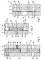
- Fig. 1 shows an embodiment of the sensor card 2 according to the invention in the plan view, the structure of the sensor card 2 for reasons of clarity on hand of Fig. 2 will be explained in more detail.
- the sensor card 2 has a sensor film 4 and a cover film 6, wherein the sensor film 4 (not shown) faces in a measurement of the liquid sample to be analyzed, whereas the cover film 6 is remote from the liquid sample. Between the sensor film 4 and the cover sheet 6, an intermediate film 8 is arranged.
- the films 4, 6, 8 is in the present embodiment to polyester films having a thickness between 80 and 120 microns and are connected to each other flat.
- the sensor film 4 has a plurality of openings 10 to 24 arranged in a line. Furthermore, two spaced-apart elongated openings 26, 28 and a ventilation opening 29 are provided in the sensor film 4.
- the intermediate film 8 On the side of the sensor film 4 facing the intermediate film 8 there are also printed electrical conductors (shown in dashed lines), wherein in each case one printed conductor 30 is arranged above the openings 16 to 24 and one further printed conductor 32 is arranged underneath the openings 16, 18, 22 and 24 , In addition, a further conductor track 34 for a reference electrode is arranged above the opening 10.
- the intermediate film 8 has a plurality of recesses 36, 38, 40, 42 and 44. Further, an elongated recess 46 is provided. In the recesses 36, which are rectangular in the present embodiment, ion-selective sensors 48 are arranged, while in the recesses 38 gas sensors, namely an oxygen sensor 50 and a carbon dioxide sensor 52, are inserted. Within the circular recess 44, a ventilation membrane 54 is provided.
- two conductivity sensors 56 are further arranged, each having two electrically conductive and spaced apart line sections 58, 60 which are printed on the sensor film 4 side facing.
- an elongated line section 62 is further printed, which acts as a reference electrode.
- a plurality of openings 64, 66 for electrical tapping and a ventilation opening 68 are provided.
- the sensor card 2 is connected to a plate 74 ( Fig. 1a ), which forms a replaceable unit with other components within the analysis system or the measuring instrument.
- a plate 74 Fig. 1a
- positioning holes 79 are provided in the sensor card, engage by the pins which are provided on the plate.
- the sensor card 2 is connected to the plate 74 such that the sensor film 4 rests on the plate.
- the plate 74 has at least one laterally open channel 76, which can be formed by a groove.
- a flow channel 78 is provided for the liquid sample, which is bounded by the wall of the channel 76 of the plate 76 on the one hand and the inside of the sensor film 4 on the other.
- the flow channel 78 leads along the openings 10 to 24 in the sensor film 4 arranged in a line, so that the liquid or gas sample can come into contact with the sensors 48, 50, 52, 56 located behind it.
- the two separate and spaced elongated openings 26 and 28 in the sensor film 4 are in fluid communication with a portion of the elongate recess 46 in the intermediate film 8, so that liquids or gases, for example, reagent solution as the inner electrolyte of the reference electrode of the ion-selective sensors or possibly Sample liquid from one opening 26 or 28 through the elongated recess 46 to the other opening 28 and 26 can flow.
- the two elongate openings 26, 28 each extend transversely, preferably at right angles to the elongated recess 46 in the intermediate foil 8, as shown in FIG Fig. 1 is shown.
- the sensor film 4 is deep-drawn, while in the intermediate film 8 and the cover sheet 6 openings 82 are provided. This ensures that the actuators acting on these areas of the sensor card do not exert any pressure on the sensor card exercise as long as they are not operated.
- Fig. 3 1 shows the ion-selective sensor 48 arranged between the sensor film 4 and the cover film 6, which consists of a carrier material 48 'which is activated or functionalized in the region of the opening 12 with an ion-selective reagent mixture (cocktail) 48 "The ion-selective cocktail fills the opening completely off and seals the sensor against the sensor film.
- a carrier material 48 ' which is activated or functionalized in the region of the opening 12 with an ion-selective reagent mixture (cocktail) 48
- ion-selective cocktail fills the opening completely off and seals the sensor against the sensor film.
- the carrier material 48 'of the ion-selective sensor 48 is disposed within the recess 36 in the intermediate film 8, so that the sensor card 2 in the region of the ion-selective sensor 48 is not thicker than in other areas in which no sensor is provided.
- the thickness of the intermediate foil 8 corresponds to the thickness of the carrier material of the sensor.
- the sensor card thus has the advantage that it has a homogeneous thickness.
- a sensor card 2 which has just been formed in this way can be attached in a particularly simple and secure manner to the plate with grooves, with which the sensor card 2 forms the flow channels, so that a high density of the flow channels is ensured.
- the ventilation membrane 54 which also in Fig. 3 is shown.
- the ion-selective sensor 48 can be electrically tapped via the opening 48 in the cover film 6 assigned to the sensor 48, in order to forward corresponding signals to the analysis unit, not shown, of the analysis system.
- the ion-selective sensor 48 has on its side facing the opening 66 for electrical tapping on a conductive coating 70, which simplifies the electrical tap.
- the ion-selective sensor 48 in the region of the opening 12 in the sensor film 4 with the liquid sample (not shown) can be wetted.
- the opening 12 in the sensor film 4 and the opening 66 are disposed offset from each other for electrical tapping.
- the electrical tap opening 66 like the other openings 64, 66 in the cover sheet, is filled with a cured electrically conductive paste 67, namely carbon paste, which facilitates picking and makes it safer.
- the paste 67 was merely in contact with the opening 66 in FIG Fig. 3 indicated by way of example.
- the ventilation membrane 54 Down in Fig. 3 the ventilation membrane 54 is shown, which rests in the recess 44 in the intermediate foil 8.
- the ventilation diaphragm 54 adjoins the ventilation opening 29 on the sensor film side and the ventilation opening 68 on the cover film side. Since the ventilation opening 68 serves the ventilation and not the electrical tap, this is not filled with carbon paste.
- the ventilation diaphragm 54 like all sensors, is larger than its associated opening 29, so that it rests securely in the recess 44 in the intermediate foil 8.
- the carrier material 52 'of the carbon dioxide sensor 52 is disposed within the recess 38 in the intermediate film 8, so that with respect to the thickness of the entire sensor card 2 also with reference on Fig. 3 described benefits occur.
- the carbon dioxide sensor 52 is in contact, on the one hand, with the first printed conductor 30 on the sensor film 4 and, on the other hand, with the second printed conductor 32 on the sensor film 4.
- the conductor track 30 can be tapped off electrically via the opening 64 in the cover film 6 and the recess 40 in the intermediate film 8, while the electrical tap of the conductor track 32 can take place via the opening 66 in the cover film 6 and the recess 42 in the intermediate film 8. This is also referred to as a via.
- the recesses 40 and 42 are filled with carbon paste, which is not shown for reasons above.
- the carrier material 52 'of the carbon dioxide sensor 52 has a coating facing the sensor film 4, preferably an imprint of silver / silver chloride and a pH-sensitive material. As activation or functionalization, an inner electrolyte 52 "and the gas-permeable membrane 52" are applied to the coating. The inner electrolyte 52 "and the gas-permeable membrane 52" fill the opening 18 in the sensor film 4.
- the carbon dioxide sensor 52 can come into contact with the sample through the opening 18 in the sensor foil 4 on its side facing the sensor foil 4.
- Fig. 5 shows the conductivity sensor 56 ( Fig. 2 ) in cross section.
- the conductivity sensor 56 is not formed as a sensor inlay, but rather consists of the above-described line sections 58 and 60, which are printed on the sensor film 4 facing side of the intermediate film 8.
- the one line section 58 is in contact with a first printed conductor 30, which is located on the sensor film 4, while the other line section 60 contacts a second printed conductor 32 located on the sensor film 4.
- the first interconnect 30 can be electrically tapped via the opening 64 in the cover film 6 and the recess 40 in the intermediate film 8, while the electrical tap of the second interconnect 32 via the opening 66 in the cover film 6 and the recess 42 in the intermediate film 8 can.
- the recesses 40 and 42 are filled with unillustrated carbon paste.
- Both line sections 58, 60 extend behind the opening 24 within the sensor film 4 and can thus be wetted via this opening 24 with the liquid sample. By entering into the opening 24 liquid, the two line sections 58, 60 are electrically connected, so that the conductivity of the liquid sample can be determined.
- the in Fig. 2 represented films, namely the sensor film 4, the cover sheet 6 and the intermediate foil 8 provided and arranged in the manner shown.
- the superimposed films 4, 6, 8 are connected to each other surface, wherein the bonding can be done by gluing, hot lamination, heat welding or high frequency welding.
- the insertion of the sensors is particularly simple when the foils 4, 6, 8 are already partially connected to one another before the insertion of the sensor inlays, for example by the lower edge 72 (FIG. Fig. 2 ) of the films 4, 6, 8 is laminated.
- the sensors are activated or functionalized only after connecting the films.
- the various analyte-specific reagent solutions for activating or functionalizing the sensors are applied to the carrier materials of the respective sensors through the openings in the sensor film and dried.
Abstract
Description
Die vorliegende Erfindung betrifft eine Sensorkarte zur Bestimmung von Analyten in Flüssigkeits- oder Gasproben mit flächig miteinander verbundenen Folien. Ferner betrifft die Erfindung ein Verfahren zur Herstellung einer solchen Sensorkarte.The present invention relates to a sensor card for the determination of analytes in liquid or gas samples with surface-connected films. Furthermore, the invention relates to a method for producing such a sensor card.
Derartige Sensorkarten kommen in Meßinstrumenten bzw. Analysensystemen zum Einsatz, bei denen eine Flüssigkeits- oder Gasprobe einer chemischen Analyse unterzogen wird, wobei die quantitative Bestimmung von verschiedenen Analyten in gasförmigen und flüssigen Proben möglich ist. Derartige Analysensysteme werden verstärkt in der Medizintechnik, der Prozeßkontrolle sowie der Lebensmittel- und Umweltanalytik eingesetzt.Such sensor cards are used in measuring instruments or analysis systems in which a liquid or gas sample is subjected to a chemical analysis, wherein the quantitative determination of different analytes in gaseous and liquid samples is possible. Such analysis systems are increasingly used in medical technology, process control and food and environmental analysis.
Die Analyse von Parametern von Körperflüssigkeiten im Rahmen des point-of-care (POC) Testings im Bereich der medizinischen Diagnostik stellt hierbei ein Haupteinsatzgebiet dieser Analysensysteme dar. Bei der Behandlung von akut und schwer erkrankten Patienten ist es für die behandelnden Ärzte wichtig, schnell und einfach präzise Informationen über beispielsweise die physiologischen Blutparameter der Patienten zu erhalten. Zu diesem Blutparametern gehören die Blutgase (pO2, pCO2, pH), die Elektrolyten (Na, K, Ca, Cl), die Leitfähigkeit des Blutes und daraus abgeleitet der Hämatokrit und die Metaboliten (Glucose, Lactat, Harnstoff, Creatinin). Zunehmend wird dabei der Ort der Analyse vom Zentrallabor in die Nähe des Patienten verlagert. Die Analysen müssen daher nicht mehr von spezialisiertem Laborpersonal durchgeführt werden, sondern können von dem Personal, das auch den Patienten betreut, durchgeführt werden. Dadurch wird ein beträchtlicher Zeitgewinn erzielt, der einer schnelleren und effizienteren Behandlung des Patienten zugute kommt.The analysis of parameters of body fluids in the context of point-of-care (POC) testing in the field of medical diagnostics represents a major field of application of these analysis systems. In the treatment of acutely and seriously ill patients, it is important for the treating physicians, fast and easy to obtain precise information about, for example, the physiological blood parameters of patients. These blood parameters include the blood gases (pO 2 , pCO 2 , pH), the electrolytes (Na, K, Ca, Cl), the conductivity of the blood and derived therefrom the hematocrit and the metabolites (glucose, lactate, urea, creatinine). Increasingly, the location of the analysis is shifted from the central laboratory to the vicinity of the patient. The analyzes therefore no longer have to be carried out by specialized laboratory personnel, but can be carried out by the staff who also looks after the patient. This results in a considerable amount of time gained, which benefits a faster and more efficient treatment of the patient.
Bei der Entwicklung der dazu eingesetzten Analysensysteme ist es insofern besonders wichtig, dass die Geräte einfach und sicher zu bedienen sind, keine komplizierten und zeitaufwendigen Wartungsmaßnahmen benötigen und die Analysenkosten pro Probe so gering wie möglich gehalten werden. Es gibt bereits verschiedene klinische Analysensysteme, die für diese Aufgabe eingesetzt werden. Sie verwenden überwiegend elektrochemische Sensoren zur Messung der Analyte. In einigen Systemen werden dabei Sensoren konventioneller Bauform bestehend aus Elektrodenkörper, Innenelektrolyt und analytselektiver Membran verwendet, die lange halten, dafür aber immer wieder zeitaufwendig gewartet werden müssen.In developing the analytical systems used for this purpose, it is particularly important that the devices are simple and safe to operate, that they do not require complicated and time-consuming maintenance measures and that the analysis costs per sample are kept as low as possible. There are already several clinical analysis systems that are used for this task. They mainly use electrochemical sensors to measure the analytes. In some systems, sensors of conventional design consisting of electrode body, inner electrolyte and analyte-selective membrane are used, which last a long time, but instead require time-consuming maintenance.
Neuere Analysengeräte verwenden zunehmend wartungsfreie, planare Sensoren, die u.a. mit Verfahren der Dünn- und Dickschichttechnik in großen Serien hergestellt werden können. Mehrere Sensoren, von denen jeder einen Analyt spezifisch bestimmen kann, werden auf einem Substrat aufgebracht. In der Durchflußzelle werden zur Ermittlung der Analytkonzentrationen Kalibrierlösung und Flüssigkeitsprobe über die Sensoren gegeben.Newer analyzers are increasingly using maintenance-free planar sensors, including: can be produced in large series using methods of thin and thick film technology. Several sensors, each of which can specifically determine an analyte, are applied to a substrate. In the flow cell calibration solution and liquid sample are given via the sensors to determine the analyte concentrations.
So wurde im Rahmen des 17. Internationalen Symposiums der International Federation of Clinical Chemistry and Laboratory Medicine (IFCC) vom 4. bis 7. Juni 1998 in Nizza, Frankreich, eine neue Generation von Sensorkarten vorgestellt, die die sogenannte Doppel-Matrix-Membran (DMM) Technologie nutzen. Die bekannten Sensorkarten mit Doppel-Matrix-Membran weisen eine Sensorfolie mit Öffnungen auf, die der zu untersuchenden Flüssigkeitsprobe in Gebrauchsstellung zugewandt wird. Auf der der Flüssigkeitsprobe abgewandten Seite der Folie ist eine Deckfolie angeordnet, auf der elektrische Leiterbahnen aus Silber/Silberchlorid aufgedruckt sind, wobei diese Leiterbahnen der Sensorfolie zugewandt sind. Zwischen der Sensorfolie und der Deckfolie sind Trägermaterialien für ionenselektive DMM-Sensoren angeordnet, die einerseits an eine Öffnung in der Sensorfolie und andererseits an eine der Leiterbahnen auf der Deckfolie angrenzen. In dieser Anordnung werden die Folien und die Sensoren verbunden, wobei die Öffnungen in der Sensorfolie kleiner als die Sensorfläche ausgebildet sind, so dass der Rand der Öffnung den Rand des Sensors niederdrückt, was letztlich zu einer Erhöhung des Randes der Öffnung fuhrt, Der elektrische Abgriff erfolgt unmittelbar an den Leiterbahnen, die sich zu diesem Zweck bis zum Rand der Deckfolie erstrecken, die größer als die Sensorfolie ausgebildet ist, so dass ein Teil der Leiterbahn nicht durch die Sensorfolie verdeckt und abgreifbar ist.For example, at the 17th International Symposium of the International Federation of Clinical Chemistry and Laboratory Medicine (IFCC), June 4-7, 1998, in Nice, France, a new generation of sensor cards introducing the so-called double matrix membrane ( DMM) technology. The known sensor cards with double-matrix membrane have a sensor film with openings, which faces the liquid sample to be examined in the position of use. On the side facing away from the liquid sample of the film, a cover sheet is arranged, on which electrical conductor tracks of silver / silver chloride are printed, these conductor tracks facing the sensor film. Support materials for ion-selective DMM sensors are arranged between the sensor film and the cover film, which on the one hand adjoin an opening in the sensor film and, on the other hand, one of the conductor tracks on the cover film. In this arrangement, the films and the sensors connected, wherein the openings in the sensor film are formed smaller than the sensor surface, so that the edge of the opening depresses the edge of the sensor, which ultimately leads to an increase of the edge of the opening, the electrical tap is directly on the conductor tracks, which to extend this purpose to the edge of the cover sheet, which is formed larger than the sensor film, so that a part of the conductor is not covered by the sensor film and can be tapped.
Innerhalb des Analysensystems ist die bekannte DMM-Sensorkarte mit einer Platte flächig verbunden, in der sich eine oder mehrere Nuten befinden. Durch diese Verbindung entsteht ein Strömungskanal für die Flüssigkeitsprobe, der von der Wandung der Nuten einerseits und von der Sensorfolie der DMM-Sensorkarte andererseits begrenzt ist. Die Öffnungen in der Sensorfolie weisen dabei zu dem Strömungskanal, so dass die Sensoren mit der durch den Strömungskanal fließenden Flüssigkeitsprobe benetzt werden können. Die bekannte DMM-Sensoxkarte hat den Nachteil, dass diese keine sichere Abdichtung der Strömungskanäle innerhalb der Platte gewährleistet.Within the analysis system, the known DMM sensor card is connected flat to a plate in which there are one or more grooves. This connection creates a flow channel for the liquid sample which is bounded on the one hand by the wall of the grooves and on the other hand by the sensor foil of the DMM sensor card. The openings in the sensor film in this case point to the flow channel, so that the sensors can be wetted with the fluid sample flowing through the flow channel. The known DMM Sensox card has the disadvantage that it does not ensure a reliable seal of the flow channels within the plate.
Die
Die
Der vorliegenden Erfindung liegt somit die Aufgabe zu Grund, eine Sensorkarte zur Bestimmung von Analyten in Flüssigkeitsproben zu schaffen, die eine sichere Abdichtung der Strömungskanäle für die Flüssigkeitsprobe gewährleistet, sowie ein Verfahren zur Herstellung einer solchen Sensorkarte anzugeben.The present invention is therefore based on the object to provide a sensor card for the determination of analytes in liquid samples, which ensures a secure seal of the flow channels for the liquid sample, and to provide a method for producing such a sensor card.
Die Lösung dieser Aufgabe erfolgt an Hand der in den Patentansprüchen 1 bzw. 16 angegebenen Merkmale. Vorteilhafte Ausführungsformen der Erfindung sind Gegenstand der Unteransprüche.The solution of this problem is based on the features specified in the
Die erfindungsgemäße Sensorkarte zur Bestimmung von Analyten in Flüssigkeits- oder Gasproben weist flächig miteinander verbundene Folien auf, Die der Flüssigkeitsprobe zugewandte Folie wird als Sensorfolie bezeichnet und ist mit Öffnungen versehen. Der Flüssigkeitsprobe zugewandt bedeutet in diesem Zusammenhang, dass die Sensorfolie mit der Flüsstgkeitsprobe innerhalb der Strömungskanäle in Kontakt kommt, d.h. die Sensorkarte soll später, wie bereits unter Bezugnahme auf den Stand der Technik beschrieben, flächig mit der Platte verbunden werden, in der sich die Nuten befinden. Die Sensorkarte weist ferner eine Deckfolie auf, die der Probe abgewandt ist, d.h. die Deckfolie tritt nicht direkt mit der Probe in Kontakt. In der Deckfolie sind ferner Öffnungen zum elektrischen Abgriff vorgesehen. Ferner weist die Sensorkarte mindestens einen Sensor auf, der zwischen der Sensorfolie und der Deckfolie angeordnet ist. Als Sensoren kommen beispielsweise potentiometrische, amperometrische oder konduktometrische analytspezifische Sensoren in Frage. Erfindungsgemäß ist zwischen der Sensorfolie und der Deckfolie mindestens eine Zwischenfolie vorgesehen. In der Zwischenfolie sind Aussparungen vorgesehen sind, wobei der Sensor in einer der Aussparungen angeordnet ist.The sensor card according to the invention for the determination of analytes in liquid or gas samples has two-dimensionally interconnected films. The film facing the liquid sample is referred to as a sensor film and is provided with openings. In this context, facing the liquid sample means that the sensor film with the fluid sample inside the Flow channels comes into contact, ie the sensor card is later, as already described with reference to the prior art, be connected flat with the plate in which the grooves are located. The sensor card also has a cover sheet facing away from the sample, ie, the cover sheet does not directly contact the sample. In the cover sheet openings for electrical tapping are also provided. Furthermore, the sensor card has at least one sensor which is arranged between the sensor film and the cover film. Examples of suitable sensors are potentiometric, amperometric or conductometric analyzer-specific sensors. According to the invention, at least one intermediate foil is provided between the sensor foil and the cover foil. In the intermediate foil recesses are provided, wherein the sensor is arranged in one of the recesses.
Die erfindungsgemäße Sensorkarte hat den Vorteil, dass sie eine homogene Dicke aufweist und eine wellige Form vermieden wird. Dies ist darauf zurückzuführen, dass die Erhöhung, die durch das Anordnen der Sensoren zwischen Sensor- und Deckfolie zwangsläufig entsteht, durch die Zwischenfolie, in deren Aussparungen die Sensoren einliegen, kompensiert wird. Eine derart eben ausgebildete Sensorkarte kann besonders einfach und sicher flächig an der Platte mit Nuten befestigt werden, mit der die Sensorkarte die Strömungskanäle ausbildet, so dass eine hohe Dichtigkeit der Strömungskanäle gewährleistet ist. Darüber hinaus bietet die erfindungsgemäße Sensorkarte die Vorteile, dass diese sehr dünn ausgebildet ist, sehr viele Sensoren fassen kann und kostengünstig herstellbar ist.The sensor card according to the invention has the advantage that it has a homogeneous thickness and a wavy shape is avoided. This is due to the fact that the increase, which inevitably arises due to the arrangement of the sensors between the sensor and cover film, is compensated for by the intermediate film in whose recesses the sensors are inserted. Such a newly formed sensor card can be attached to the plate with grooves in a particularly simple and secure manner, with which the sensor card forms the flow channels, so that a high density of the flow channels is ensured. In addition, the sensor card according to the invention has the advantages that it is very thin, can hold a large number of sensors and is inexpensive to produce.
In einer besonders vorteilhaften Ausführungsform der erfindungsgemäßen Sensorkarte ist die Dicke der Zwischenfolie derart gewählt, dass diese der Dicke des Sensors entspricht oder größer ist. Im ersten Fall wird eine absolut ebene Sensorkarte geschaffen, während im zweiten Fall kleinere nach innen weisende Wölbungen entstehen können, wobei dies im Hinblick auf die Dichtigkeit der Strömungskanäle noch immer vorteilhafter ist, als vorspringende Wölbungen, wie sie bei der bekannten DMM-Sensorkarte auftreten.In a particularly advantageous embodiment of the sensor card according to the invention, the thickness of the intermediate film is selected such that it corresponds to the thickness of the sensor or is larger. In the first case, an absolutely flat sensor card is created, while in the second case, smaller inwardly facing bulges may arise, which is still more advantageous in view of the tightness of the flow channels, as protruding bulges, as they occur in the known DMM sensor card.
Um ein möglichst einfaches und sicheres elektrisches Abgreifen durch die Öffnungen in der Deckfolie zu ermöglichen, sind die Öffnungen in einer weiteren bevorzugten Ausführungsform der Erfindung mit einer ausgehärteten, elektrisch leitenden Paste gefüllt. Hierbei kann es sich vorzugsweise um Kohlepaste handeln.In order to enable a simple and secure electrical tapping through the openings in the cover sheet, the openings are filled in a further preferred embodiment of the invention with a cured, electrically conductive paste. This may preferably be carbon paste.
In einer bevorzugten Ausführungsform der erfindungsgemäßen Sensorkarte ist der Sensor als ionenselektiver Sensor ausgebildet. Der ionenselektive Sensor kann einerseits über eine der Öffnungen in der Deckfolie elektrisch abgegriffen und andererseits über eine der Öffnungen in der Sensorfolie mit der Flüssigkeitsprobe benetzt werden.In a preferred embodiment of the sensor card according to the invention, the sensor is designed as an ion-selective sensor. On the one hand, the ion-selective sensor can be electrically tapped off via one of the openings in the cover film and, on the other hand, can be wetted with the liquid sample via one of the openings in the sensor film.
Vorteilhafterweise ist die Öffnung zum elektrischen Abgriff des ionenselektiven Sensors in einer weiteren Ausführungsform der Erfindung versetzt zu der Öffnung in der Sensorfolie angeordnet. Unter versetzt ist hierbei zu verstehen, dass die Öffnung in der Deckfolie in der Draufsicht auf die Sensorkarte und die Öffnung in der Sensorfolie im Abstand zueinander angeordnet sind, wobei vorzugsweise keine Überschneidung der beiden Öffnungen besteht.Advantageously, the opening for the electrical tap of the ion-selective sensor is arranged in a further embodiment of the invention offset from the opening in the sensor film. Under offset here is to be understood that the opening in the cover sheet in the plan view of the sensor card and the opening in the sensor film are arranged at a distance from each other, preferably there is no overlap of the two openings.
In einer weiteren Ausführungsform der erfindungsgemäßen Sensorkarte weist der ionenselektive Sensor ein in der Aussparung einliegendes Trägermaterial auf. Als Trägermaterial kommt beispielsweise saugfähiges Papier in Frage. Im Bereich der Öffnung der Sensorfolie ist das Trägermaterial mit einer ionenselektiven Reagenzmischung aktiviert bzw. funktionalisiert. Die Reagenzmischung füllt dabei die Öffnung in der Sensorfolie vollständig aus, so dass der ionenselektive Sensor gegenüber der Sensorfolie sicher abgedichtet ist.In a further embodiment of the sensor card according to the invention, the ion-selective sensor has a carrier material lying in the recess. As a carrier material is for example absorbent paper in question. In the region of the opening of the sensor film, the carrier material is activated or functionalized with an ion-selective reagent mixture. The reagent mixture completely fills the opening in the sensor film so that the ion-selective sensor is securely sealed against the sensor film.
Das Trägermaterial des ionenselektiven Sensors weist in einer besonders bevorzugten Ausführungsform an seiner der Öffnung zum elektrischen Abgriff zugewandten Seite eine leitfähige Beschichtung auf. Die leitfähige Beschichtung dient dem elektrischen Anschluß des ionsenselektiven Sensors und gewährleistet ein sicheres elektrisches Abgreifen durch die Öffnung in der Deckfolie.In a particularly preferred embodiment, the carrier material of the ion-selective sensor has a conductive coating on its side facing the opening for electrical tapping. The conductive coating serves to electrically connect the sensor-selective sensor and ensures secure electrical tapping through the opening in the cover sheet.
In einer besonders bevorzugten Ausführungsform der Erfindung weist die Sensorfolie der Zwischenfolie zugewandte, aufgedruckte elektrische Leiterbahnen auf. Derartige Leiterbahnen können beispielsweise mittels Siebdruck aufgebracht werden und ebenfalls aus Kohlepaste bestehen. Durch den Siebdruck können auch besonders flache Leiterbahnen erzeugt werden, die ebenfalls zur Lösung der erfindungsgemäßen Aufgabe beitragen. Die Leiterbahnen können jeweils über die Öffnungen zum elektrischen Abgriff und mindestens eine der Aussparungen in der Zwischenfolie elektrisch angeschlossen werden. Man kann bei dieser Ausführungsform von einer Durchkontaktierung sprechen, die sich einfacher und platzsparender als das seitliche Abgreifen an der bekannten DMM-Sensorkarte gestaltet.In a particularly preferred embodiment of the invention, the sensor film of the intermediate film facing, printed electrical conductor tracks. Such strip conductors can be applied for example by means of screen printing and also consist of carbon paste. Due to the screen printing, it is also possible to produce particularly flat printed conductors, which likewise contribute to achieving the object according to the invention. The conductor tracks can each be electrically connected via the openings for electrical tapping and at least one of the recesses in the intermediate foil. One can speak in this embodiment of a via, which is simpler and less space designed as the lateral tap on the known DMM sensor card.
Der Sensor ist in einer weiteren Ausführungsform der erfindungsgemäßen Sensorkarte als Gassensor ausgebildet. Der Gassensor steht mit einer ersten Leiterbahn und einer zweiten Leiterbahn auf der Sensorfolie in Kontakt. Des weiteren kann der Gassensor über eine der Öffnungen in der Sensorfolie mit der Probe in Kontakt kommen.The sensor is formed in a further embodiment of the sensor card according to the invention as a gas sensor. The gas sensor is in contact with a first printed conductor and a second printed conductor on the sensor film. Furthermore, the gas sensor can come into contact with the sample via one of the openings in the sensor film.
Der Gassensor ist in einer weiteren Ausführungsform der erfindungsgemäßen Sensorkarte ein Kohlendioxidsensor, der aus einer Trägerfolie besteht, die eine der Sensorfolie zugewandte Beschichtung, vorzugsweise eine Bedruckung aus Silber/Silberchlorid- und einem pH-sensitiven-Material aufweist.In a further embodiment of the sensor card according to the invention, the gas sensor is a carbon dioxide sensor which consists of a carrier film which has a coating facing the sensor film, preferably a printing of silver / silver chloride and a pH-sensitive material.
Der Gassensor ist in einer weiteren Ausführungsform der Erfindung ein Sauerstoffsensor. Der Sauerstoffsensor besteht aus einer Trägerfolie mit hierauf aufgebrachten, vorzugsweise aufgedruckten Schichten eines als Arbeitselektrode und eines als Referenzelektrode geeigneten Materials, die der Sensorfolie zugewandt sind.The gas sensor is an oxygen sensor in another embodiment of the invention. The oxygen sensor consists of a carrier foil with, preferably printed on it, layers of a material suitable as a working electrode and a reference electrode, which are applied to the sensor foil.
Gemäß einer weiteren vorteilhaften Ausführungsform der Erfindung ist der Sensor ein Leitfähigkeitssensor. Dieser weist zwei elektrisch leitfähige, voneinander beabstandete Leitungsabschnitte auf, die auf der der Sensorfolie zugewandten Seite der Zwischenfolie aufgedruckt sind. Die Leitungsabschnitte können beispielsweise wie die Leiterbahnen mittels Siebdruck aufgebracht werden und aus einer getrockneten Kohlepaste bestehen. Der eine Leitungsabschnitt steht mit einer ersten Leiterbahn auf der Sensorfolie und der andere Leitungsabschnitt steht mit einer zweiten Leiterbahn auf der Sensorfolie in Kontakt. Die Leitfähigkeitssensoren können über Öffnungen in der Sensorfolie mit der Flüssigkeitsprobe benetzt und dadurch elektrisch leitend verbunden werden, um die Leitfähigkeit der Flüssigkeitsprobe zu ermitteln.According to a further advantageous embodiment of the invention, the sensor is a conductivity sensor. This has two electrically conductive, spaced-apart line sections, which are printed on the side facing the sensor film side of the intermediate film. The line sections, for example, like the tracks can be applied by screen printing and consist of a dried carbon paste. The one line section is connected to a first conductor track on the sensor film and the other line section is in contact with a second conductor track on the sensor film. The conductivity sensors can be wetted via openings in the sensor film with the liquid sample and thereby electrically connected to determine the conductivity of the liquid sample.
Um eine ausreichende Belüftung zu gewährleisten, ist bei einer vorteilhaften Ausführungsform der Sensorkarte in mindestens einer der Aussparungen in der Zwischenfolie eine Belüftungsmembran angeordnet. Die Belüftungsmembran grenzt einerseits an eine Belüftungsöffnung in der Sensorfolie und andererseits an eine Belüftungsöffnung in der Deckfolie an.In order to ensure adequate ventilation, in an advantageous embodiment of the sensor card in at least one of the recesses in the intermediate foil, a ventilation membrane is arranged. The ventilation membrane adjoins, on the one hand, a ventilation opening in the sensor film and, on the other hand, a ventilation opening in the cover film.
Zuweilen ist es bei den Analysensystemen wünschenswert, zwei voneinander getrennte Strömungskanäle innerhalb der Platte, auf der die Sensorfolie befestigt wird, durch einen schmalen Kanal zu verbinden, der nur durch größeren Aufwand in der Platte selbst erzeugt werden könnte. Um einen solchen Kanal zu erzeugen, ist in einer besonders bevorzugten Ausführungsform der erfindungsgemäßen Sensorkarte eine der Aussparungen in der Zwischenfolie länglich ausgebildet, wobei die längliche Aussparung mit mindestens zwei separaten Öffnungen in der Sensorfolie in Strömungsverbindung steht. Somit kann durch eine der Öffnungen in der Sensorfolie eine Flüssigkeit oder ein Gas, wie beispielsweise eine Reagenzlösung, in die längliche Aussparung gelangen, um von dort durch die zweite der beiden Öffnungen in der Sensorfolie wieder auszutreten. Dies kann beispielsweise dazu benutzt werden, einen Strömungskanal für eine Reagenzlösung mit einem Strömungskanal für eine Flüssigkeitsprobe zu verbinden. Eine Verbindung der Strömungskanäle für Reagenzlösung und Flüssigkeitsprobe ist beispielsweise dann vorzusehen, wenn der Innenelektrolyt einer Referenzelektrode, der in einem Beutel zur Verfügung gestellt werden kann, während der Messungen intermittierend über den Strömungskanal für die Reagenzlösung dem Probenkanal zugeführt werden soll.Sometimes it is desirable in the analyzer systems to connect two separate flow channels within the plate on which the sensor film is mounted, through a narrow channel which could only be produced by greater expense in the plate itself. In order to produce such a channel, in a particularly preferred embodiment of the sensor card according to the invention, one of the recesses in the intermediate film is elongated, wherein the elongated recess is in flow communication with at least two separate openings in the sensor film. Thus, through one of the openings in the sensor film, a liquid or a gas, such as a reagent solution, can enter the elongated recess to exit from there through the second of the two openings in the sensor film. This can be used, for example, to connect a flow channel for a reagent solution with a flow channel for a liquid sample. A connection of the flow channels for reagent solution and liquid sample is to be provided, for example, when the inner electrolyte of a reference electrode, which can be provided in a bag, during the measurements should be supplied intermittently via the flow channel for the reagent solution to the sample channel.
In einer besonders bevorzugten Ausführungsform der erfindungsgemäßen Sensorkarte sind die beiden separaten Öffnungen in der Sensorfolie ebenfalls länglich ausgebildet und verlaufen quer, vorzugsweise im rechten Winkel, zu der länglichen Aussparung in der Zwischenfolie. Dies gewährleistet, dass die beiden länglichen Öffnungen in der Sensorfolie und die längliche Aussparung in der Zwischenfolie auch tatsächlich wie gewünscht in Strömungsverbindung stehen. Während bei punktförmigen Öffnungen in der Sensorfolie geringe Toleranzen beim Übereinanderlegen der Folien eingehalten werden müssten, um eine Strömungsverbindung zu gewährleisten, fallen bei länglichen Öffnungen in der Sensorfolie auch größere Verschiebungen der Folien zueinander nicht ins Gewicht, da die längliche Öffnung die längliche Aussparung in mehreren Punkten überlagern kann. Die Fertigung der Sensorkarte ist somit vereinfacht.In a particularly preferred embodiment of the sensor card according to the invention, the two separate openings in the sensor film are also elongated and extend transversely, preferably at right angles, to the elongated recess in the intermediate film. This ensures that the two elongate openings in the sensor film and the elongated recess in the intermediate film are actually in fluid communication as desired. While at punctiform openings in the sensor film low tolerances would have to be met when superimposing the films in order to ensure a flow connection fall with elongated openings in the sensor film and larger shifts of the films to each other not significant, since the elongated opening, the elongated recess in several points can overlay. The production of the sensor card is thus simplified.
Das erfindungsgemäße Verfahren zur Herstellung einer Sensorkarte zur Bestimmung von Analyten in Flüssigkeits- oder Gasproben mit flächig miteinander verbundenen Folien weist folgende Verfahrensschritte auf. Zunächst wird eine Sensorfolie mit Öffnungen, eine Deckfolie mit Öffnungen zum elektrischen Abgriff und mindestens eine Zwischenfolie, in der Aussparungen vorgesehen sind, zur Verfügung gestellt. Danach wird mindestens ein Sensor oder der Teil eines Sensors in einer der Aussparungen der Zwischenfolie angeordnet. Abschließend werden die übereinander angeordneten Folien flächig miteinander verbunden, wobei die Zwischenfolie zwischen Sensorfolie und Deckfolie angeordnet ist.The method according to the invention for the production of a sensor card for the determination of analytes in liquid or gas samples with laminarly interconnected foils has the following method steps. First, a sensor foil with openings, a cover foil with openings for electrical tapping and at least one intermediate foil, in which recesses are provided, are made available. Thereafter, at least one sensor or the part of a sensor is arranged in one of the recesses of the intermediate foil. Finally, the superimposed films are connected to each other surface, wherein the intermediate film between the sensor film and cover sheet is arranged.
Das erfindungsgemäße Verfahren sieht zwei Alternativen vor. Entweder kann der fertige Sensor oder nur ein Teil eines in einem nachfolgenden Verfahrensschritt noch fertigzustellenden Sensors in der Aussparung der Zwischenfolie angeordnet werden. So kann anstelle des fertigen Sensors auch nur das Trägermaterial des Sensors, das bereits mit Elektroden versehen sein kann, in die Zwischenfolie eingelegt werden. Nach dem Verbinden der Folien wird das Trägermaterial dann aktiviert bzw. funktionalisiert. Das Trägermaterial kann aus unterschiedlichen Materialien bestehen. Die Aktivierung bzw. Funktionalisierung kann dadurch erfolgen, dass auf das Trägermaterial durch die Öffnung in der Sensorfolie ein oder mehrere weitere Materialien aufgebracht werden, die der Aktivierung oder Funktionalisierung dienen. Der Einbau eines fertigen Sensors hat den Vorteil der einfachen Herstellung, während der Einbau eines noch zu aktivierenden bzw. funktionalisierenden Teils eines Sensors, den Vorteil hat, dass der Teil des Sensors mit dem aufzubringenden Material für die Aktivierung bzw. Funktionalisierung den fertigen Sensor gegenüber der Sensorfolie sicher abdichtet.The method according to the invention provides for two alternatives. Either the finished sensor or only a part of a still to be finished in a subsequent process step sensor can be arranged in the recess of the intermediate foil. Thus, instead of the finished sensor, only the carrier material of the sensor, which may already be provided with electrodes, into the intermediate film be inserted. After bonding the films, the carrier material is then activated or functionalized. The carrier material may consist of different materials. The activation or functionalization can be effected by applying to the carrier material through the opening in the sensor film one or more further materials which serve for activation or functionalization. The incorporation of a finished sensor has the advantage of ease of manufacture, while the installation of a yet to be activated or functionalizing part of a sensor, has the advantage that the part of the sensor with the applied material for the activation or functionalization of the finished sensor against the Sensor foil securely sealed.
In einer besonders bevorzugten Ausführungsform des erfindungsgemäßen Verfahrens wird zumindest eine der Folien, d.h. Sensor- oder Deckfolie, vor dem Anordnen des Sensors oder Teils des Sensors in einer der Aussparungen mit der Zwischenfolie teilweise flächig verbunden. Ein solches Verfahren ermöglicht ein einfacheres Anordnen der Sensoren innerhalb der Aussparung in der Zwischenfolie, da durch die zum Teil befestigte Deck- oder Sensorfolie ein Herausfallen des Sensors verhindert wird.In a particularly preferred embodiment of the process according to the invention, at least one of the films, i. Sensor or cover sheet, partially connected before the placement of the sensor or part of the sensor in one of the recesses with the intermediate film. Such a method allows a simpler arrangement of the sensors within the recess in the intermediate film, as is prevented by the partially attached cover or sensor film from falling out of the sensor.
In einer weiteren besonders vorteilhaften Ausführungsform wird sowohl die Sensorfolie als auch die Deckfolie vor dem Anordnen des Sensors oder Teils des Sensors in einer der Aussparungen mit der Zwischenfolie teilweise flächig verbunden. Neben dem in der vorbeschriebenen Ausführungsform genannten Vorteil, hat dies zusätzlich den Vorteil, dass bereits erkannt werden kann, ob die Öffnungen und Aussparungen in den Folien schon vor dem kompletten Verbinden richtig zueinander angeordnet sind.In a further particularly advantageous embodiment, both the sensor film and the cover film are partially connected in a planar manner before arranging the sensor or part of the sensor in one of the recesses with the intermediate film. In addition to the advantage mentioned in the above-described embodiment, this additionally has the advantage that it can already be recognized whether the openings and recesses in the films are already arranged correctly relative to one another before the complete connection.
Eine weitere Ausführungsform des erfindungsgemäßen Verfahrens ist dadurch gekennzeichnet, dass vor dem Zurverfügungstellen der Sensorfolie Leiterbahnen auf die der Zwischenfolie zuzuwendende Seite der Sensorfolie aufgedruckt werden, vorzugsweise durch Siebdruck. Siebdruck ist ein zuverlässiges Verfahren, das die Erzeugung besonders flacher Leiterbahnen ermöglicht.A further embodiment of the method according to the invention is characterized in that, before the sensor film is made available, printed conductors are printed on the side of the sensor film facing the intermediate film, preferably by screen printing. Screen printing is a reliable one Method which enables the production of particularly flat printed conductors.
In einer weiteren Ausführungsform der Erfindung werden vor dem Zurverfügungstellen der Zwischenfolie Leitungsabschnitte auf die der Sensorfolie zuzuwendende Seite der Zwischenfolie aufgedruckt, vorzugsweise durch Siebdruck. Siebdruck wird von der Fertigung auch auf der der Zwischenfolie zugewandten Seite der Deckfolie angestrebt. Im Prinzip kann auf beide Seiten der Zwischenfolie und die Innenseiten der Deck- und Sensorfolie gedruckt werden. Das Verbinden der Folien erfolgt vorzugsweise durch Kleben, Heißlaminieren, Hitzeverschweißen oder Hochfrequenzschweißen.In a further embodiment of the invention, line sections are printed onto the side of the intermediate film facing the sensor film before the intermediate film is made available, preferably by screen printing. Screen printing is also aimed at by production on the side of the cover film facing the intermediate film. In principle, it is possible to print on both sides of the intermediate foil and the insides of the cover and sensor foil. The bonding of the foils is preferably carried out by gluing, hot lamination, heat welding or high frequency welding.
Einzelne oder alle Folien der Karte können lokal ausgespart sein, um zusammen mit der Umgebung der Sensorkarte weitere Funktionen zu ermöglichen und um eine exakte Positionierung der erfindungsgemäßen Sensorkarte gegenüber einer Platte mit Nut zu ermöglichen.Individual or all foils of the card can be recessed locally in order to enable further functions together with the surroundings of the sensor card and to enable an exact positioning of the sensor card according to the invention in relation to a panel with a groove.
Die Sensorkarte kann so positioniert werden, dass, wenn notwendig, einzelne Öffnungen der Sensorfolie befüllt werden können, um die Sensoren zu aktivieren bzw. funktionalisieren. Für ionenselektiven Sensoren können die entsprechenden ionenselektiven Reagenzmischungen (Cocktails) aufgebracht werden. Die jeweiligen ionenselektiven Reagenzmischungen (Cocktails) für die verschiedenen ionenselektiven Sensoren werden in die betreffenden Öffnungen auf das Trägermaterial getropft und getrocknet. Auch können gaspermeable Membranen für Gassensoren aufdosiert und getrocknet werden. Es ist auch denkbar, die funktionalen Schichten vor dem endgültigen Zusammenfügen der Folien direkt auf die Sensorinlays aufzubringen. Andere bzw. zusätzliche Materialien für die Aktivierung bzw. Funktionalisierung, wie sie z.B. für Biosensoren eingesetzt werden, können analog aufgebracht werden.The sensor card can be positioned so that, if necessary, individual openings of the sensor film can be filled in order to activate or functionalize the sensors. For ion-selective sensors, the corresponding ion-selective reagent mixtures (cocktails) can be applied. The respective ion-selective reagent mixtures (cocktails) for the various ion-selective sensors are dropped into the relevant openings on the carrier material and dried. Gas-permeable membranes for gas sensors can also be added and dried. It is also conceivable to apply the functional layers directly onto the sensor inlays prior to the final assembly of the films. Other or additional materials for the activation or functionalization, as e.g. used for biosensors can be applied analogously.
Die Sensorkarte kann einfach an die analytischen Aufgaben angepasst werden, indem die Art und die Anzahl der in ihrer Zwischenfolie integrierten Sensoren auf die zu analysierenden Stoffe abgestimmt wird. Der Aufbau der Sensorkarte ist in dieser Hinsicht als modular anzusehen. Außerdem ist es auch möglich, weitere Sensoren direkt auf die Zwischenfolie zu drucken anstatt sie als Sensorinlays in die Aussparungen der Zwischenteile einzulegen.The sensor card can be easily adapted to the analytical tasks by adjusting the type and number of sensors integrated in their intermediate foil to the substances to be analyzed. The structure of the sensor card is in view as modular in this respect. In addition, it is also possible to print additional sensors directly on the intermediate film instead of inserting them as sensor inlays in the recesses of the intermediate parts.
Im Folgenden wird die Erfindung an Hand einer beispielhaften Ausführungsform unter Bezugnahme auf die beigefügten Figuren eingehender erläutert.In the following the invention with reference to an exemplary embodiment with reference to the accompanying figures will be explained in more detail.
Es zeigen:
- Fig. 1
- eine Draufsicht auf eine Ausführungsform der erfindungsgemäßen Sensorkarte,
- Fig. 1 a
- eine Draufsicht auf eine Anordnung mit einer Sensorkarte und einer strukturierten Platte,
- Fig. 2
- eine perspektivische Explosionsdarstellung der Sensorkarte von
Fig. 1 , - Fig. 3
- eine Schnittansicht entlang der Schnittlinie A-A von
Fig. 1 in vergrößerter Darstellung, - Fig. 4
- eine Schnittansicht entlang der Schnittlinie B-B von
Fig. 1 in vergrößerter Darstellung und - Fig. 5
- eine Schnittansicht entlang der Schnittlinie C-C von
Fig. 1 in vergrößerter Darstellung.
- Fig. 1
- a plan view of an embodiment of the sensor card according to the invention,
- Fig. 1 a
- a plan view of an arrangement with a sensor card and a structured plate,
- Fig. 2
- an exploded perspective view of the sensor card of
Fig. 1 . - Fig. 3
- a sectional view along the section line AA of
Fig. 1 in an enlarged view, - Fig. 4
- a sectional view taken along the section line BB of
Fig. 1 in an enlarged view and - Fig. 5
- a sectional view taken along the section line CC of
Fig. 1 in an enlarged view.
Die Sensorkarte 2 weist eine Sensorfolie 4 und eine Deckfolie 6 auf, wobei die Sensorfolie 4 bei einer Messung der zu analysierenden Flüssigkeitsprobe (nicht dargestellt) zugewandt ist, wohingegen die Deckfolie 6 der Flüssigkeitsprobe abgewandt ist. Zwischen der Sensorfolie 4 und der Deckfolie 6 ist eine Zwischenfolie 8 angeordnet. Bei den Folien 4, 6, 8 handelt es sich in der vorliegenden Ausführungsform um Polyesterfolien, die eine Dicke zwischen 80 und 120 µm haben und flächig miteinander verbunden sind.The
Die Sensorfolie 4 weist mehrere in einer Linie angeordnete Öffnungen 10 bis 24 auf. Des weiteren sind zwei voneinander beabstandete längliche Öffnungen 26, 28 sowie eine Belüftungsöffnung 29 in der Sensorfolie 4 vorgesehen.The
Auf der der Zwischenfolie 8 zugewandten Seite der Sensorfolie 4 sind ferner aufgedruckte elektrische Leiterbahnen (gestrichelt dargestellt) vorgesehen, wobei jeweils eine Leiterbahn 30 oberhalb der Öffnungen 16 bis 24 und jeweils eine weitere Leiterbahn 32 unterhalb der Öffnungen 16, 18, 22 und 24 angeordnet ist. Darüber hinaus ist oberhalb der Öffnung 10 eine weitere Leiterbahn 34 für eine Referenzelektrode angeordnet.On the side of the
Die Zwischenfolie 8 weist mehrere Aussparungen 36, 38, 40, 42 und 44 auf. Ferner ist eine längliche Aussparung 46 vorgesehen. In den Aussparungen 36, die bei der vorliegenden Ausführungsform rechteckig ausgebildet sind, sind ionenselektive Sensoren 48 angeordnet, während in die Aussparungen 38 Gassensoren, nämlich ein Sauerstoffsensor 50 und ein Kohlendioxidsensor 52, eingelegt sind. Innerhalb der kreisrunden Aussparung 44 ist eine Belüftungsmembran 54 vorgesehen.The
Auf der Zwischenfolie 8 sind ferner zwei Leitfähigkeitssensoren 56 angeordnet, die jeweils zwei elektrisch leitfähige und voneinander beabstandete Leitungsabschnitte 58, 60 aufweisen, die auf der der Sensorfolie 4 zugewandten Seite aufgedruckt sind. Auf dieser Seite der Zwischenfolie 8 ist ferner ein langgestreckter Leitungsabschnitt 62 aufgedruckt, der als Referenzelektrode fungiert.On the
In der Deckfolie 6 sind wiederum mehrere Öffnungen 64, 66 zum elektrischen Abgriff sowie eine Belüftungsöffnung 68 vorgesehen.In the
Die Sensorkarte 2 ist mit einer Platte 74 verbunden (
Die Sensorkarte 2 ist derart mit der Platte 74 verbunden, dass die Sensorfolie 4 auf der Platte aufliegt. Die Platte 74 weist mindestens einen seitlich geöffneten Kanal 76 auf, der von einer Nut gebildet werden kann. Dadurch wird ein Strömungskanal 78 für die Flüssigkeitsprobe geschaffen, der von der Wandung des Kanals 76 der Platte 76 einerseits und der Innenseite der Sensorfolie 4 andererseits begrenzt ist. Der Strömungskanal 78 führt dabei entlang der in einer Linie angeordneten Öffnungen 10 bis 24 in der Sensorfolie 4, so dass die Flüssigkeits- oder Gasprobe mit den dahinterliegenden Sensoren 48, 50, 52, 56 in Kontakt treten kann.The
Die beiden separaten und voneinander beabstandeten länglichen Öffnungen 26 und 28 in der Sensorfolie 4 stehen mit jeweils einem Abschnitt der länglichen Aussparung 46 in der Zwischenfolie 8 in Strömungsverbindung, so dass Flüssigkeiten oder Gase, beispielsweise Reagenzlösung als Innenelektrolyt der Referenzelektrode der ionenselektiven Sensoren oder ggf. auch Probenflüssigkeit von einer Öffnung 26 bzw. 28 durch die längliche Aussparung 46 zu der anderen Öffnung 28 bzw. 26 strömen kann. Vorteilhafterweise erstrecken sich die beiden länglichen Öffnungen 26, 28 jeweils quer, vorzugsweise im rechten Winkel zu der länglichen Aussparung 46 in der Zwischenfolie 8, wie dies in
Darüber hinaus weist die Sensorkarte Bereiche 81 auf, an denen nicht dargestellte Betätigungsorgane zum Öffnen nicht dargestellter Flüssigkeitsbeutel angreifen, die in dem Disposable vorgesehen sind. In diesen Bereichen 81 ist die Sensorfolie 4 tiefgezogen, während in der Zwischenfolie 8 und der Deckfolie 6 Öffnungen 82 vorgesehen sind. Dadurch wird erreicht, dass die an diesen Bereichen der Sensorkarte angreifenden Betätigungorgane keinen Druck auf die Sensorkarte ausüben, solange sie nicht betätigt werden.In addition, the
Die Funktionsweise sowie die Vorteile der vorliegenden Ausführungsform sollen nun an Hand der
Das Trägermaterial 48' des ionenselektiven Sensors 48 ist innerhalb der Aussparung 36 in der Zwischenfolie 8 angeordnet, so dass die Sensorkarte 2 im Bereich des ionenselektiven Sensors 48 nicht dicker als in anderen Bereichen ist, in denen kein Sensor vorgesehen ist. Zu diesem Zweck entspricht die Dicke der Zwischenfolie 8 der Dicke des Trägermaterials des Sensors. Die Sensorkarte hat somit den Vorteil, dass diese eine homogene Dicke aufweist. Eine derart eben ausgebildete Sensorkarte 2 kann besonders einfach und sicher flächig an der Platte mit Nuten befestigt werden, mit der die Sensorkarte 2 die Strömungskanäle ausbildet, so dass eine hohe Dichtigkeit der Strömungskanäle gewährleistet ist. Entsprechendes gilt auch für die später beschriebenen anderen Sensoren sowie für die Belüftungsmembran 54, die ebenfalls in
Der ionenselektive Sensor 48 kann über die dem Sensor 48 zugeordnete Öffnung 66 in der Deckfolie 6 elektrisch abgegriffen werden, um entsprechende Signale an die nicht dargestellte Auswerteinheit des Analysensystems weiterzuleiten. Darüber hinaus weist der ionenselektive Sensor 48 an seiner der Öffnung 66 zum elektrischen Abgriff zugewandten Seite eine leitfähige Beschichtung 70 auf, die den elektrischen Abgriff vereinfacht. Auf der anderen Seite kann der ionenselektive Sensor 48 im Bereich der Öffnung 12 in der Sensorfolie 4 mit der Flüssigkeitsprobe (nicht dargestellt) benetzt werden.The ion-
Wie aus den
Unten in
Das Trägermaterial 52' des Kohlendioxidsensors 52 weist eine der Sensorfolie 4 zugewandte Beschichtung auf, vorzugsweise eine Bedruckung aus Silber/Silberchlorid- und einem pH-sensitiven Material. Als Aktivierung oder Funktionalisierung ist auf der Beschichtung ein Innenelektrolyt 52" und die gaspermeable Membran 52" aufgebracht. Der Innenelektrolyt 52" und die gaspermeable Membran 52" füllen die Öffnung 18 in der Sensorfolie 4 aus.The carrier material 52 'of the
Während der elektrische Abgriff von hinten, also über die Deckfolie, erfolgt, kann der Kohlendioxidsensor 52 an seiner der Sensorfolie 4 zugewandten Seite durch die Öffnung 18 in der Sensorfolie 4 mit der Probe in Kontakt kommen.While the electrical tapping takes place from the rear, ie via the cover foil, the
Beide Leitungsabschnitte 58, 60 erstrecken sich hinter die Öffnung 24 innerhalb der Sensorfolie 4 und können somit über diese Öffnung 24 mit der Flüssigkeitsprobe benetzt werden. Durch die in die Öffnung 24 eintretende Flüssigkeit werden die beiden Leitungsabschnitte 58, 60 elektrisch leitend verbunden, so dass die Leitfähigkeit der Flüssigkeitsprobe ermittelt werden kann.Both
Im Folgenden soll das erfindungsgemäße Verfahren an Hand der
Werden nur die Trägermaterialien von noch nicht fertigen Sensoren in die Aussparungen eingelegt, so werden die Sensoren erst nach dem Verbinden der Folien aktiviert oder funktionalisiert. Hierzu werden die verschiedenen analytspezifischen Reagenzlösungen zur Aktivierung oder Funktionalisierung der Sensoren durch die Öffnungen in der Sensorfolie auf die Trägermaterialien der jeweiligen Sensoren aufgebracht und getrocknet.If only the carrier materials of not yet finished sensors are inserted into the recesses, the sensors are activated or functionalized only after connecting the films. For this purpose, the various analyte-specific reagent solutions for activating or functionalizing the sensors are applied to the carrier materials of the respective sensors through the openings in the sensor film and dried.
Claims (22)
- Sensor card for determining analytes in liquid or gaseous samples, in which films are connected together over their area, having a sensor film (4), adjacent the sample, which has openings (10-14, 26, 28, 29), having a covering film (6) remote from the sample, and having at least one sensor or one part of a sensor (48, 50, 52) which is arranged between the sensor film (4) and the covering film (6), at least one intermediate film (8) which has apertures (36, 38, 40, 42, 44, 46) being provided between the sensor film (4) and the covering film (6) and the sensor (48, 50, 52) being arranged in one of the apertures (36, 38), characterised in that the covering film (6) remote from the sample is provided with openings (64, 66) for electrical pick-off from the at least one sensor (48, 50, 52).
- Sensor card according to claim 1, characterised in that the thickness of the intermediate film (8) is equal to or greater than the thickness of the sensor or the part of the sensor (48, 50, 52),
- Sensor card according to claim 1 or 2, characterised in that the openings (64, 66) for electrical pick-off are filled with a cured electrically conductive paste (67).
- Sensor card according to one of the preceding claims, characterised in that the sensor is an ion-selective sensor (48) from which on the one hand electrical pick-off is possible through one of the openings (66) in the covering film (6) and which on the other hand is able to make contact with the liquid or gaseous sample through one of the openings (10, 12, 14, 20) in the sensor film (4).
- Sensor card according to claim 4, characterised in that the opening (66) for electrical pick-off in the covering film (6) is arranged in an offset position from the opening (10, 12, 14, 20) in the sensor film (4).
- Sensor card according to either of claims 4 and 5, characterised in that the ion-selective sensor (48) has a substrate material (48') which is situated in the aperture (36) and which is activated by an ion-selective reagent mixture (48") in the region of the opening (10, 12, 14, 20) in the sensor film (4).
- Sensor card according to claim 6, characterised in that the substrate material has a conductive coating (70) on its side adjacent the opening (66) for electrical pick-off.
- Sensor card according to one of the preceding claims, characterised in that the sensor film (4) has printed electrical conductors (30, 32, 34) adjacent the intermediate film (8), electrical pick-off from the conductors (30, 32, 34) being possible through each of the openings (64, 66) for electrical pick-off and through at least one of the apertures (40, 42) in the intermediate film (8).
- Sensor card according to claim 8, characterised in that the sensor is a gas sensor which is in contact with a first conductor (30) and a second conductor (32) on the sensor film (4) and which is able to come into contact with the liquid or gaseous sample through one of the openings (18, 22) in the sensor film (4).
- Sensor card according to claim 9, characterised in that the gas sensor is a carbon dioxide sensor (52), and in particular a carbon dioxide sensor which has a substrate material (52') which has a coating adjacent the sensor film (4) and preferably a printed coating of silver/silver chloride material and of a pH-sensitive material, a reference electrolyte (52") and a gas-permeable membrane (52") being applied to the coating as activating means.
- Sensor card according to claim 9, characterised in that the gas sensor is an oxygen sensor (50) and in particular an oxygen sensor which has a substrate material which has applied to it, and preferably printed on it, layers of a material which is suitable to act as a working electrode and of a material which is suitable to act as a reference electrode, a reference electrolyte and a gas-permeable membrane being applied to the coating as activating means.
- Sensor card according to claim 8, characterised in that the sensor is a conductivity sensor (56) which has two electrically conductive portions of electrical line (58, 60) which are spaced apart from one another and which are printed on the side of the intermediate film (8) adjacent the sensor film (4), one portion of electrical line (58) being in contact with a first conductor (30) on the sensor film (4) and the other portion of electrical line (60) being in contact with a second conductor (32) on the sensor film (4) and the two portions of electrical line (58, 60) being able to be wetted, and connected by an electrically conductive connection, by the liquid sample through an opening (16, 24) within the sensor film (4).
- Sensor card according to one of the preceding claims, characterised in that an air-admission membrane (54) is arranged in at least one of the apertures (44) in the intermediate film (8), the air-admission membrane (51) adjoining on the one hand an air-admission opening (29) in the sensor film (4) and on the other hand an air-admission opening (68) in the covering film (6).
- Sensor card according to one of the preceding claims, characterised in that one (46) of the apertures in the intermediate film (8) is of an elongated form, the elongated aperture (46) being in flow-permitting connection with at least two separate openings (26, 28) in the sensor film (4).
- Sensor card according to claim 14, characterised in that the two separate openings (26, 28) are of an elongated form and extend transversely, and preferably at right angles, to the elongated aperture (46) in the intermediate film (8).
- Arrangement for determining analytes in liquid or gaseous samples, having a sensor card according to one of the preceding claims and a plate having at least one passage which is open laterally, wherein the sensor film of the sensor card is fastened to the plate to form a passage for the flow of the sample which is closed off laterally.
- Method for producing a sensor card for determining analytes in liquid samples in which films are connected together over their area, the method having the following method steps
supply of a sensor film having openings, of a covering film having openings for electrical pick-off, and of at least one intermediate film in which apertures are provided,
arranging of at least one sensor or one part of a sensor in one of the apertures in the intermediate film, and
connection over their area of the films when arranged one above the other, the intermediate film being arranged between the sensor film and the covering film. - Method according to claim 17, characterised in that, before the sensor or the part of a sensor is arranged in one of the apertures, at least one of the films is connected to the intermediate film over part of its area.
- Method according to claim 18, characterised in that, before the sensor or the part of a sensor is arranged in one of the apertures, both the sensor film and the covering film are connected to the intermediate film over part of their area.
- Method according to one of claims 17 to 19, characterised in that, before the sensor film is supplied, conductors are printed on that side of the sensor film which is to be adjacent the intermediate film, preferably by screen printing.
- Method according to one of claims 17 to 20, characterised in that, before the intermediate film is supplied, portions of electrical line are printed on that side of the intermediate film which is to be adjacent the sensor film, preferably by screen printing.
- Method according to one of claims 17 to 21, characterised in that the connection is made by adhesive bonding, hot lamination, heat welding or high-frequency welding.
Applications Claiming Priority (2)
| Application Number | Priority Date | Filing Date | Title |
|---|---|---|---|
| DE10353938 | 2003-11-18 | ||
| DE10353938A DE10353938A1 (en) | 2003-11-18 | 2003-11-18 | Sensor card for the determination of analytes in liquid or gas samples and method for producing such a sensor card |
Publications (2)
| Publication Number | Publication Date |
|---|---|
| EP1533614A1 EP1533614A1 (en) | 2005-05-25 |
| EP1533614B1 true EP1533614B1 (en) | 2011-09-21 |
Family
ID=34428790
Family Applications (1)
| Application Number | Title | Priority Date | Filing Date |
|---|---|---|---|
| EP04026357A Not-in-force EP1533614B1 (en) | 2003-11-18 | 2004-11-05 | Sensor card for determining analytes in liquid and gaseous samples and method for producing same |
Country Status (8)
| Country | Link |
|---|---|
| US (1) | US7837845B2 (en) |
| EP (1) | EP1533614B1 (en) |
| JP (1) | JP4594044B2 (en) |
| KR (1) | KR101056126B1 (en) |
| CN (1) | CN100580442C (en) |
| AT (1) | ATE525646T1 (en) |
| DE (1) | DE10353938A1 (en) |
| ES (1) | ES2373951T3 (en) |
Families Citing this family (15)
| Publication number | Priority date | Publication date | Assignee | Title |
|---|---|---|---|---|
| JP5629094B2 (en) * | 2007-01-19 | 2014-11-19 | アエロクライン・アクチボラゲットAerocrine Ab | Analysis equipment |
| EP1986007A1 (en) * | 2007-04-27 | 2008-10-29 | Radiometer Medical ApS | A sensor assembly for body fluids |
| DE202008009938U1 (en) | 2008-07-23 | 2008-10-09 | Bürkert Werke GmbH & Co.KG | sensor system |
| KR101077919B1 (en) | 2010-03-16 | 2011-10-31 | 대윤계기산업 주식회사 | Card-type mult tester |
| US9119748B2 (en) * | 2011-10-28 | 2015-09-01 | Kimberly-Clark Worldwide, Inc. | Electronic discriminating device for body exudate detection |
| US8816149B2 (en) | 2011-10-28 | 2014-08-26 | Kimberly-Clark Worldwide, Inc. | System for detection and monitoring of body exudates using a gas emitting substance for use in interactive toilet training |
| US8933292B2 (en) | 2011-10-28 | 2015-01-13 | Kimberly-Clark Worldwide, Inc. | Absorbent article with sensor array for body exudate detection |
| DE102011056271A1 (en) | 2011-12-12 | 2013-06-13 | sense2care GmbH | Device for analyzing patient samples |
| DE102011056273B4 (en) | 2011-12-12 | 2013-11-21 | sense2care GmbH | Fluid reservoir for a device for analyzing patient samples |
| DE102016210303A1 (en) * | 2016-06-10 | 2017-12-14 | Airbus Defence and Space GmbH | Sensor carrier film for an object and method for equipping an object with a sensor system |
| DE102016117441A1 (en) * | 2016-09-16 | 2018-03-22 | Dr. Ing. H.C. F. Porsche Aktiengesellschaft | Traction battery and vehicle with such |
| DE102016118526A1 (en) | 2016-09-29 | 2018-03-29 | Krohne Messtechnik Gmbh | Conductivity meter for measuring an electrical conductivity of a liquid medium |
| EP3559664B1 (en) * | 2016-12-23 | 2020-12-09 | Radiometer Medical ApS | Multiple-use sensor assembly for body fluids |
| CN107390519B (en) * | 2017-06-22 | 2020-01-07 | 西安交通大学 | Screening method of direct current cable material formula |
| CN115406946B (en) * | 2022-08-16 | 2023-06-30 | 山东卓越生物技术股份有限公司 | PO (potential of Hydrogen) of disposable instant detection card and sensor chip 2 Electrode preparation method |
Family Cites Families (27)
| Publication number | Priority date | Publication date | Assignee | Title |
|---|---|---|---|---|
| US4225410A (en) * | 1978-12-04 | 1980-09-30 | Technicon Instruments Corporation | Integrated array of electrochemical sensors |
| US4454007A (en) * | 1983-01-27 | 1984-06-12 | E. I. Du Pont De Nemours And Company | Ion-selective layered sensor and methods of making and using the same |
| JPH0612350B2 (en) * | 1985-06-26 | 1994-02-16 | 株式会社東芝 | Distribution type ion sensor body |
| JPS63151845A (en) * | 1986-12-16 | 1988-06-24 | Fuji Photo Film Co Ltd | Ion activity measuring apparatus |
| DE3810186A1 (en) * | 1987-08-01 | 1989-10-05 | Siegert Gmbh | SENSOR FOR MEASURING THE ACTIVITY OF IONS AND METHOD FOR THE PRODUCTION THEREOF |
| US5405510A (en) * | 1992-05-18 | 1995-04-11 | Ppg Industries, Inc. | Portable analyte measuring system for multiple fluid samples |
| FR2701117B1 (en) | 1993-02-04 | 1995-03-10 | Asulab Sa | Electrochemical measurement system with multizone sensor, and its application to glucose measurement. |
| US5700360A (en) * | 1995-10-31 | 1997-12-23 | Chiron Diagnostics Corporation | Fluoroelastomer gasket for blood sensors |
| US5858452A (en) * | 1996-05-16 | 1999-01-12 | Sendx Medical, Inc. | Method for fabricating wiring substrate with subminiature thru-holes |
| US6080668A (en) * | 1996-05-30 | 2000-06-27 | International Business Machines Corporation | Sequential build-up organic chip carrier and method of manufacture |
| DE19631530C2 (en) * | 1996-07-23 | 2000-03-09 | Inst Chemo Biosensorik | Ion selective sensor |
| US5830337A (en) * | 1996-07-24 | 1998-11-03 | Gastech, Inc. | Electrochemical gas sensor |
| DE19747875A1 (en) | 1997-10-20 | 1999-05-06 | Meinhard Prof Dr Knoll | Method for measuring variable sizes and device for carrying out the method |
| JP3350810B2 (en) * | 1997-12-29 | 2002-11-25 | 太陽誘電株式会社 | Ion sensor and ion sensor plate |
| JPH11281757A (en) * | 1998-03-30 | 1999-10-15 | Fujitsu Ltd | Atmospheric pollutant measurement system |
| US6123820A (en) * | 1998-06-05 | 2000-09-26 | Grupo Ch-Werfen, S.A. | Sensor cartridges |
| US6287451B1 (en) * | 1999-06-02 | 2001-09-11 | Handani Winarta | Disposable sensor and method of making |
| DE19929264A1 (en) | 1999-06-25 | 2001-01-11 | Meinhard Knoll | Universal transducer |
| AU7854700A (en) * | 1999-10-04 | 2001-05-10 | Nanostream, Inc. | Modular microfluidic devices comprising sandwiched stencils |
| US20030057108A1 (en) * | 1999-12-10 | 2003-03-27 | Ramamurthi Sridharan | Device and method for accelerated hydration of dry chemical sensors |
| DE10003507B4 (en) * | 2000-01-27 | 2004-06-03 | Knoll, Meinhard, Prof. Dr. | Device and method for the removal of liquids from the body's own tissue and determination of substance concentrations in this liquid |
| KR100446468B1 (en) * | 2001-05-18 | 2004-09-01 | 주식회사 아이센스 | Biosensors with porous chromatographic membranes and enhanced sampling capability |
| US6572745B2 (en) * | 2001-03-23 | 2003-06-03 | Virotek, L.L.C. | Electrochemical sensor and method thereof |
| US6960466B2 (en) * | 2001-05-31 | 2005-11-01 | Instrumentation Laboratory Company | Composite membrane containing a cross-linked enzyme matrix for a biosensor |
| US6652720B1 (en) * | 2001-05-31 | 2003-11-25 | Instrumentation Laboratory Company | Analytical instruments, biosensors and methods thereof |
| US6872297B2 (en) * | 2001-05-31 | 2005-03-29 | Instrumentation Laboratory Company | Analytical instruments, biosensors and methods thereof |
| GB0123416D0 (en) * | 2001-09-28 | 2001-11-21 | Memquest Ltd | Non-volatile memory control |
-
2003
- 2003-11-18 DE DE10353938A patent/DE10353938A1/en not_active Withdrawn
-
2004
- 2004-11-05 EP EP04026357A patent/EP1533614B1/en not_active Not-in-force
- 2004-11-05 AT AT04026357T patent/ATE525646T1/en active
- 2004-11-05 ES ES04026357T patent/ES2373951T3/en active Active
- 2004-11-17 US US10/992,193 patent/US7837845B2/en not_active Expired - Fee Related
- 2004-11-18 JP JP2004333878A patent/JP4594044B2/en not_active Expired - Fee Related
- 2004-11-18 KR KR1020040094498A patent/KR101056126B1/en not_active IP Right Cessation
- 2004-11-18 CN CN200410094794A patent/CN100580442C/en not_active Expired - Fee Related
Also Published As
| Publication number | Publication date |
|---|---|
| KR20050048513A (en) | 2005-05-24 |
| US20090321258A1 (en) | 2009-12-31 |
| DE10353938A1 (en) | 2005-06-23 |
| EP1533614A1 (en) | 2005-05-25 |
| JP4594044B2 (en) | 2010-12-08 |
| CN100580442C (en) | 2010-01-13 |
| KR101056126B1 (en) | 2011-08-11 |
| ATE525646T1 (en) | 2011-10-15 |
| CN1624468A (en) | 2005-06-08 |
| JP2005148077A (en) | 2005-06-09 |
| US7837845B2 (en) | 2010-11-23 |
| ES2373951T3 (en) | 2012-02-10 |
Similar Documents
| Publication | Publication Date | Title |
|---|---|---|
| DE60122517T2 (en) | ELECTRICALLY CONDUCTIVE PATTERN FOR MONITORING THE FILLING OF MEDICAL DEVICES | |
| EP1533614B1 (en) | Sensor card for determining analytes in liquid and gaseous samples and method for producing same | |
| DE60225723T2 (en) | MICRO LEAD BAND | |
| EP1977225B1 (en) | Electrochemical biosensor analysis system | |
| DE60122588T2 (en) | ELECTROCHEMICAL TEST STRIP CARDS CONTAINING A BUILT-IN DRYING AGENT | |
| DE60020076T2 (en) | SMALL VOLUME IN VITRO ANALYTES SENSOR | |
| DE60025334T2 (en) | DISPOSAL TESTS WITH INTRA-GENERATED REAGENT / BLOOD SEPARATION LAYER | |
| DE60035981T2 (en) | ELECTROCHEMICAL BIOSENSOR TEST STRIP, METHOD OF MANUFACTURE AND ELECTROCHEMICAL BIOSENSOR | |
| DE60012946T2 (en) | INTERFERENCE-REDUCED DISPOSABLE SENSOR AND MANUFACTURING METHOD | |
| DE19822123C2 (en) | Method and device for the detection of analytes | |
| DE602004006148T2 (en) | METHOD FOR REDUCING THE EFFECT OF A DIRECT INTERFERENCE CURRENT IN AN ELECTROCHEMICAL TEST STRIP | |
| DE102010002915B4 (en) | Microfluidic sensor | |
| EP1542803A1 (en) | Multiple capillary sensor analysis system | |
| DE112018005405B4 (en) | PH CONTROL TO DETECT ANALYTES | |
| DE19848112C2 (en) | Minimally invasive sensor system | |
| DE19546535C2 (en) | Measuring cartridge for liquid or gaseous samples, process for their operation and their use | |
| DE2127142A1 (en) | Analyzer | |
| DE102005017364B4 (en) | Analyzer with replaceable test field carrier | |
| DE202015101592U1 (en) | Electrochemical biosensing instrument and system for analyte measurement with sample fill detection | |
| EP1393807B1 (en) | Testing device for examining a biological sample | |
| WO1999020999A1 (en) | Method for measuring modifiable variables and device for implementing said method | |
| DE10234564A1 (en) | biosensor | |
| DE102017121914A1 (en) | Sensor element and method for producing a sensor element | |
| EP3646029B1 (en) | Detection system and process for its production | |
| AT520605B1 (en) | Sensor cassette |
Legal Events
| Date | Code | Title | Description |
|---|---|---|---|
| PUAI | Public reference made under article 153(3) epc to a published international application that has entered the european phase |
Free format text: ORIGINAL CODE: 0009012 |
|
| AK | Designated contracting states |
Kind code of ref document: A1 Designated state(s): AT BE BG CH CY CZ DE DK EE ES FI FR GB GR HU IE IS IT LI LU MC NL PL PT RO SE SI SK TR |
|
| AX | Request for extension of the european patent |
Extension state: AL HR LT LV MK YU |
|
| 17P | Request for examination filed |
Effective date: 20050428 |
|
| RIN1 | Information on inventor provided before grant (corrected) |
Inventor name: SCHROERS, ALEXANDER Inventor name: MAGER, GERHARD, DR. Inventor name: HAECKER, JUERGEN Inventor name: CHEMNITIUS, GABRIELE, DR. Inventor name: ABEL, PETRA |
|
| AKX | Designation fees paid |
Designated state(s): AT BE BG CH CY CZ DE DK EE ES FI FR GB GR HU IE IS IT LI LU MC NL PL PT RO SE SI SK TR |
|
| 17Q | First examination report despatched |
Effective date: 20071220 |
|
| GRAP | Despatch of communication of intention to grant a patent |
Free format text: ORIGINAL CODE: EPIDOSNIGR1 |
|
| GRAS | Grant fee paid |
Free format text: ORIGINAL CODE: EPIDOSNIGR3 |
|
| GRAA | (expected) grant |
Free format text: ORIGINAL CODE: 0009210 |
|
| AK | Designated contracting states |
Kind code of ref document: B1 Designated state(s): AT BE BG CH CY CZ DE DK EE ES FI FR GB GR HU IE IS IT LI LU MC NL PL PT RO SE SI SK TR |
|
| REG | Reference to a national code |
Ref country code: GB Ref legal event code: FG4D Free format text: NOT ENGLISH |
|
| REG | Reference to a national code |
Ref country code: CH Ref legal event code: EP |
|
| REG | Reference to a national code |
Ref country code: IE Ref legal event code: FG4D Free format text: LANGUAGE OF EP DOCUMENT: GERMAN |
|
| REG | Reference to a national code |
Ref country code: DE Ref legal event code: R096 Ref document number: 502004012876 Country of ref document: DE Effective date: 20111117 |
|
| REG | Reference to a national code |
Ref country code: NL Ref legal event code: VDEP Effective date: 20110921 |
|
| PG25 | Lapsed in a contracting state [announced via postgrant information from national office to epo] |
Ref country code: SE Free format text: LAPSE BECAUSE OF FAILURE TO SUBMIT A TRANSLATION OF THE DESCRIPTION OR TO PAY THE FEE WITHIN THE PRESCRIBED TIME-LIMIT Effective date: 20110921 Ref country code: FI Free format text: LAPSE BECAUSE OF FAILURE TO SUBMIT A TRANSLATION OF THE DESCRIPTION OR TO PAY THE FEE WITHIN THE PRESCRIBED TIME-LIMIT Effective date: 20110921 |
|
| REG | Reference to a national code |
Ref country code: ES Ref legal event code: FG2A Ref document number: 2373951 Country of ref document: ES Kind code of ref document: T3 Effective date: 20120210 |
|
| PG25 | Lapsed in a contracting state [announced via postgrant information from national office to epo] |
Ref country code: GR Free format text: LAPSE BECAUSE OF FAILURE TO SUBMIT A TRANSLATION OF THE DESCRIPTION OR TO PAY THE FEE WITHIN THE PRESCRIBED TIME-LIMIT Effective date: 20111222 Ref country code: CY Free format text: LAPSE BECAUSE OF FAILURE TO SUBMIT A TRANSLATION OF THE DESCRIPTION OR TO PAY THE FEE WITHIN THE PRESCRIBED TIME-LIMIT Effective date: 20110921 Ref country code: SI Free format text: LAPSE BECAUSE OF FAILURE TO SUBMIT A TRANSLATION OF THE DESCRIPTION OR TO PAY THE FEE WITHIN THE PRESCRIBED TIME-LIMIT Effective date: 20110921 |
|
| REG | Reference to a national code |
Ref country code: IE Ref legal event code: FD4D |
|
| PG25 | Lapsed in a contracting state [announced via postgrant information from national office to epo] |
Ref country code: IS Free format text: LAPSE BECAUSE OF FAILURE TO SUBMIT A TRANSLATION OF THE DESCRIPTION OR TO PAY THE FEE WITHIN THE PRESCRIBED TIME-LIMIT Effective date: 20120121 Ref country code: CZ Free format text: LAPSE BECAUSE OF FAILURE TO SUBMIT A TRANSLATION OF THE DESCRIPTION OR TO PAY THE FEE WITHIN THE PRESCRIBED TIME-LIMIT Effective date: 20110921 Ref country code: SK Free format text: LAPSE BECAUSE OF FAILURE TO SUBMIT A TRANSLATION OF THE DESCRIPTION OR TO PAY THE FEE WITHIN THE PRESCRIBED TIME-LIMIT Effective date: 20110921 Ref country code: IE Free format text: LAPSE BECAUSE OF FAILURE TO SUBMIT A TRANSLATION OF THE DESCRIPTION OR TO PAY THE FEE WITHIN THE PRESCRIBED TIME-LIMIT Effective date: 20110921 |
|
| BERE | Be: lapsed |
Owner name: FRESENIUS MEDICAL CARE DEUTSCHLAND G.M.B.H. Effective date: 20111130 |
|
| PG25 | Lapsed in a contracting state [announced via postgrant information from national office to epo] |
Ref country code: PL Free format text: LAPSE BECAUSE OF FAILURE TO SUBMIT A TRANSLATION OF THE DESCRIPTION OR TO PAY THE FEE WITHIN THE PRESCRIBED TIME-LIMIT Effective date: 20110921 Ref country code: NL Free format text: LAPSE BECAUSE OF FAILURE TO SUBMIT A TRANSLATION OF THE DESCRIPTION OR TO PAY THE FEE WITHIN THE PRESCRIBED TIME-LIMIT Effective date: 20110921 Ref country code: RO Free format text: LAPSE BECAUSE OF FAILURE TO SUBMIT A TRANSLATION OF THE DESCRIPTION OR TO PAY THE FEE WITHIN THE PRESCRIBED TIME-LIMIT Effective date: 20110921 Ref country code: PT Free format text: LAPSE BECAUSE OF FAILURE TO SUBMIT A TRANSLATION OF THE DESCRIPTION OR TO PAY THE FEE WITHIN THE PRESCRIBED TIME-LIMIT Effective date: 20120123 Ref country code: EE Free format text: LAPSE BECAUSE OF FAILURE TO SUBMIT A TRANSLATION OF THE DESCRIPTION OR TO PAY THE FEE WITHIN THE PRESCRIBED TIME-LIMIT Effective date: 20110921 |
|
| PG25 | Lapsed in a contracting state [announced via postgrant information from national office to epo] |
Ref country code: MC Free format text: LAPSE BECAUSE OF NON-PAYMENT OF DUE FEES Effective date: 20111130 |
|
| REG | Reference to a national code |
Ref country code: CH Ref legal event code: PL |
|
| PLBE | No opposition filed within time limit |
Free format text: ORIGINAL CODE: 0009261 |
|
| STAA | Information on the status of an ep patent application or granted ep patent |
Free format text: STATUS: NO OPPOSITION FILED WITHIN TIME LIMIT |
|
| PG25 | Lapsed in a contracting state [announced via postgrant information from national office to epo] |
Ref country code: CH Free format text: LAPSE BECAUSE OF NON-PAYMENT OF DUE FEES Effective date: 20111130 Ref country code: DK Free format text: LAPSE BECAUSE OF FAILURE TO SUBMIT A TRANSLATION OF THE DESCRIPTION OR TO PAY THE FEE WITHIN THE PRESCRIBED TIME-LIMIT Effective date: 20110921 Ref country code: LI Free format text: LAPSE BECAUSE OF NON-PAYMENT OF DUE FEES Effective date: 20111130 |
|
| 26N | No opposition filed |
Effective date: 20120622 |
|
| PG25 | Lapsed in a contracting state [announced via postgrant information from national office to epo] |
Ref country code: BE Free format text: LAPSE BECAUSE OF NON-PAYMENT OF DUE FEES Effective date: 20111130 |
|
| REG | Reference to a national code |
Ref country code: DE Ref legal event code: R097 Ref document number: 502004012876 Country of ref document: DE Effective date: 20120622 |
|
| REG | Reference to a national code |
Ref country code: AT Ref legal event code: MM01 Ref document number: 525646 Country of ref document: AT Kind code of ref document: T Effective date: 20111105 |
|
| PG25 | Lapsed in a contracting state [announced via postgrant information from national office to epo] |
Ref country code: AT Free format text: LAPSE BECAUSE OF NON-PAYMENT OF DUE FEES Effective date: 20111105 |
|
| PG25 | Lapsed in a contracting state [announced via postgrant information from national office to epo] |
Ref country code: LU Free format text: LAPSE BECAUSE OF NON-PAYMENT OF DUE FEES Effective date: 20111105 |
|
| PG25 | Lapsed in a contracting state [announced via postgrant information from national office to epo] |
Ref country code: BG Free format text: LAPSE BECAUSE OF FAILURE TO SUBMIT A TRANSLATION OF THE DESCRIPTION OR TO PAY THE FEE WITHIN THE PRESCRIBED TIME-LIMIT Effective date: 20111221 |
|
| PG25 | Lapsed in a contracting state [announced via postgrant information from national office to epo] |
Ref country code: TR Free format text: LAPSE BECAUSE OF FAILURE TO SUBMIT A TRANSLATION OF THE DESCRIPTION OR TO PAY THE FEE WITHIN THE PRESCRIBED TIME-LIMIT Effective date: 20110921 |
|
| PG25 | Lapsed in a contracting state [announced via postgrant information from national office to epo] |
Ref country code: HU Free format text: LAPSE BECAUSE OF FAILURE TO SUBMIT A TRANSLATION OF THE DESCRIPTION OR TO PAY THE FEE WITHIN THE PRESCRIBED TIME-LIMIT Effective date: 20110921 |
|
| PGFP | Annual fee paid to national office [announced via postgrant information from national office to epo] |
Ref country code: DE Payment date: 20131128 Year of fee payment: 10 Ref country code: GB Payment date: 20131127 Year of fee payment: 10 |
|
| PGFP | Annual fee paid to national office [announced via postgrant information from national office to epo] |
Ref country code: IT Payment date: 20131113 Year of fee payment: 10 Ref country code: FR Payment date: 20131128 Year of fee payment: 10 |
|
| PGFP | Annual fee paid to national office [announced via postgrant information from national office to epo] |
Ref country code: ES Payment date: 20131128 Year of fee payment: 10 |
|
| REG | Reference to a national code |
Ref country code: DE Ref legal event code: R119 Ref document number: 502004012876 Country of ref document: DE |
|
| GBPC | Gb: european patent ceased through non-payment of renewal fee |
Effective date: 20141105 |
|
| REG | Reference to a national code |
Ref country code: FR Ref legal event code: ST Effective date: 20150731 |
|
| PG25 | Lapsed in a contracting state [announced via postgrant information from national office to epo] |
Ref country code: GB Free format text: LAPSE BECAUSE OF NON-PAYMENT OF DUE FEES Effective date: 20141105 Ref country code: DE Free format text: LAPSE BECAUSE OF NON-PAYMENT OF DUE FEES Effective date: 20150602 |
|
| PG25 | Lapsed in a contracting state [announced via postgrant information from national office to epo] |
Ref country code: FR Free format text: LAPSE BECAUSE OF NON-PAYMENT OF DUE FEES Effective date: 20141201 |
|
| PG25 | Lapsed in a contracting state [announced via postgrant information from national office to epo] |
Ref country code: IT Free format text: LAPSE BECAUSE OF NON-PAYMENT OF DUE FEES Effective date: 20141105 |
|
| REG | Reference to a national code |
Ref country code: ES Ref legal event code: FD2A Effective date: 20160129 |
|
| PG25 | Lapsed in a contracting state [announced via postgrant information from national office to epo] |
Ref country code: ES Free format text: LAPSE BECAUSE OF NON-PAYMENT OF DUE FEES Effective date: 20141106 |