EP1533532A1 - Gelenkvorrichtung - Google Patents
Gelenkvorrichtung Download PDFInfo
- Publication number
- EP1533532A1 EP1533532A1 EP03730554A EP03730554A EP1533532A1 EP 1533532 A1 EP1533532 A1 EP 1533532A1 EP 03730554 A EP03730554 A EP 03730554A EP 03730554 A EP03730554 A EP 03730554A EP 1533532 A1 EP1533532 A1 EP 1533532A1
- Authority
- EP
- European Patent Office
- Prior art keywords
- hinge
- hinge member
- fitting hole
- hinge pin
- biasing
- Prior art date
- Legal status (The legal status is an assumption and is not a legal conclusion. Google has not performed a legal analysis and makes no representation as to the accuracy of the status listed.)
- Withdrawn
Links
Images


Classifications
-
- H—ELECTRICITY
- H04—ELECTRIC COMMUNICATION TECHNIQUE
- H04B—TRANSMISSION
- H04B1/00—Details of transmission systems, not covered by a single one of groups H04B3/00 - H04B13/00; Details of transmission systems not characterised by the medium used for transmission
- H04B1/38—Transceivers, i.e. devices in which transmitter and receiver form a structural unit and in which at least one part is used for functions of transmitting and receiving
-
- G—PHYSICS
- G06—COMPUTING OR CALCULATING; COUNTING
- G06F—ELECTRIC DIGITAL DATA PROCESSING
- G06F1/00—Details not covered by groups G06F3/00 - G06F13/00 and G06F21/00
- G06F1/16—Constructional details or arrangements
- G06F1/1613—Constructional details or arrangements for portable computers
- G06F1/1633—Constructional details or arrangements of portable computers not specific to the type of enclosures covered by groups G06F1/1615 - G06F1/1626
- G06F1/1675—Miscellaneous details related to the relative movement between the different enclosures or enclosure parts
- G06F1/1681—Details related solely to hinges
-
- G—PHYSICS
- G06—COMPUTING OR CALCULATING; COUNTING
- G06F—ELECTRIC DIGITAL DATA PROCESSING
- G06F1/00—Details not covered by groups G06F3/00 - G06F13/00 and G06F21/00
- G06F1/16—Constructional details or arrangements
- G06F1/1613—Constructional details or arrangements for portable computers
- G06F1/1615—Constructional details or arrangements for portable computers with several enclosures having relative motions, each enclosure supporting at least one I/O or computing function
- G06F1/1616—Constructional details or arrangements for portable computers with several enclosures having relative motions, each enclosure supporting at least one I/O or computing function with folding flat displays, e.g. laptop computers or notebooks having a clamshell configuration, with body parts pivoting to an open position around an axis parallel to the plane they define in closed position
-
- H—ELECTRICITY
- H04—ELECTRIC COMMUNICATION TECHNIQUE
- H04M—TELEPHONIC COMMUNICATION
- H04M1/00—Substation equipment, e.g. for use by subscribers
- H04M1/02—Constructional features of telephone sets
-
- H—ELECTRICITY
- H04—ELECTRIC COMMUNICATION TECHNIQUE
- H04M—TELEPHONIC COMMUNICATION
- H04M1/00—Substation equipment, e.g. for use by subscribers
- H04M1/02—Constructional features of telephone sets
- H04M1/0202—Portable telephone sets, e.g. cordless phones, mobile phones or bar type handsets
- H04M1/0206—Portable telephones comprising a plurality of mechanically joined movable body parts, e.g. hinged housings
- H04M1/0208—Portable telephones comprising a plurality of mechanically joined movable body parts, e.g. hinged housings characterized by the relative motions of the body parts
- H04M1/0214—Foldable telephones, i.e. with body parts pivoting to an open position around an axis parallel to the plane they define in closed position
- H04M1/0216—Foldable in one direction, i.e. using a one degree of freedom hinge
-
- E—FIXED CONSTRUCTIONS
- E05—LOCKS; KEYS; WINDOW OR DOOR FITTINGS; SAFES
- E05D—HINGES OR SUSPENSION DEVICES FOR DOORS, WINDOWS OR WINGS
- E05D11/00—Additional features or accessories of hinges
- E05D11/08—Friction devices between relatively-movable hinge parts
- E05D11/082—Friction devices between relatively-movable hinge parts with substantially radial friction, e.g. cylindrical friction surfaces
-
- E—FIXED CONSTRUCTIONS
- E05—LOCKS; KEYS; WINDOW OR DOOR FITTINGS; SAFES
- E05D—HINGES OR SUSPENSION DEVICES FOR DOORS, WINDOWS OR WINGS
- E05D11/00—Additional features or accessories of hinges
- E05D11/10—Devices for preventing movement between relatively-movable hinge parts
- E05D11/1028—Devices for preventing movement between relatively-movable hinge parts for maintaining the hinge in two or more positions, e.g. intermediate or fully open
- E05D11/1078—Devices for preventing movement between relatively-movable hinge parts for maintaining the hinge in two or more positions, e.g. intermediate or fully open the maintaining means acting parallel to the pivot
-
- E—FIXED CONSTRUCTIONS
- E05—LOCKS; KEYS; WINDOW OR DOOR FITTINGS; SAFES
- E05F—DEVICES FOR MOVING WINGS INTO OPEN OR CLOSED POSITION; CHECKS FOR WINGS; WING FITTINGS NOT OTHERWISE PROVIDED FOR, CONCERNED WITH THE FUNCTIONING OF THE WING
- E05F1/00—Closers or openers for wings, not otherwise provided for in this subclass
- E05F1/08—Closers or openers for wings, not otherwise provided for in this subclass spring-actuated, e.g. for horizontally sliding wings
- E05F1/10—Closers or openers for wings, not otherwise provided for in this subclass spring-actuated, e.g. for horizontally sliding wings for swinging wings, e.g. counterbalance
- E05F1/12—Mechanisms in the shape of hinges or pivots, operated by springs
- E05F1/1207—Mechanisms in the shape of hinges or pivots, operated by springs with a coil spring parallel with the pivot axis
- E05F1/1223—Mechanisms in the shape of hinges or pivots, operated by springs with a coil spring parallel with the pivot axis with a compression or traction spring
-
- E—FIXED CONSTRUCTIONS
- E05—LOCKS; KEYS; WINDOW OR DOOR FITTINGS; SAFES
- E05Y—INDEXING SCHEME ASSOCIATED WITH SUBCLASSES E05D AND E05F, RELATING TO CONSTRUCTION ELEMENTS, ELECTRIC CONTROL, POWER SUPPLY, POWER SIGNAL OR TRANSMISSION, USER INTERFACES, MOUNTING OR COUPLING, DETAILS, ACCESSORIES, AUXILIARY OPERATIONS NOT OTHERWISE PROVIDED FOR, APPLICATION THEREOF
- E05Y2999/00—Subject-matter not otherwise provided for in this subclass
Definitions
- This invention relates to a hinge device suited to be used for a cellular telephone, a notebook type personal computer and the like.
- a cellular telephone includes, as shown in FIGS. 18 and 19, a transmission section A and a reception section B.
- the transmission section A and the reception section B are turnably connected to each other through a hinge device (not shown).
- the turning range of the transmission section A and the reception section B is restricted between a folding position as shown in FIG. 18 where the transmission section A and the reception section B are abutted with each other and a using position as shown in FIG. 19, when an angle formed between the transmission section A and the reception section B is, for example 170 degrees.
- a hinge device used in the above-mentioned cellular telephone includes, as described, for example, in Japanese Patent Application Laid-Open Nos. 2001-193727 and 2002-106544, a first and a second hinge member which are arranged opposite to each other.
- the first hinge member is fixed to either the transmission section A or the reception section B of the cellular telephone, and the second hinge member is fixed to the other.
- the first and second hinge members are turnably connected to each other through a hinge pin.
- the transmission section A and the reception section B of the cellular telephone are turnably connected to each other through the hinge device.
- the hinge device includes a movable member C and a fixing member D shown in FIG. 20.
- the movable member C connected to the first hinge member such that the movable member C is non-tunable but movable in the axial direction of the hinge pin.
- the movable member C is abutted with the fixing member D by a coiled spring (not shown).
- a pair of projections C1, C2 are formed on an abutment surface of the movable member C with respect to the fixing member D, and a pair of recesses D1, D2 are formed on an abutment surface of the fixing member D with respect to the movable member C.
- the pair of projections C1, C2 are arranged such that when the reception section B is located in a position within a predetermined range of angle (biasing angle range) between a folding position and a position away by an angle ⁇ toward a using position side from the folding position, the pair of projections C1, C2 are inserted in one end parts of the recesses D1, D2, respectively, in the peripheral direction of the fixing member D.
- the projections C1, C2 When the projections C1, C2 are inserted in the one end parts of the recesses D1, D2, respectively, the projections C1, C2 are abutted with the slanted bottom surfaces (cam surfaces) of the recesses D1, D2, respectively.
- the biasing force of the coiled spring is converted into a turn biasing force in one direction (the direction as indicated by an arrow of FIG. 18).
- the movable member C is turn biased with respect to the fixing member D and the reception section B is turned to the folding position. Then, the reception section B is maintained in the folding position.
- the pair of projections C1, C2 are inserted in the other end parts of the recesses D2, D1, respectively, in the peripheral direction of the fixing member D and abutted with the bottom surfaces of the other end parts of the recesses D2, D1, respectively.
- the bottom surfaces of the other end parts of the recesses D1, D2 are inclined in the direction opposite to the bottom surfaces of one end parts of the recesses D1, D2.
- the biasing force of the coiled spring is converted to a turn biasing force in the other direction (direction as indicated by an arrow of FIG. 19).
- the reception section B is turned to the using position and held in the using position.
- the angle formed between the movable member C and the fixing member D is represented by ⁇ , in the range of angle of ⁇ ⁇ ⁇ ⁇ ⁇ , i.e., in the outside of the biasing angle range, the projections C1, C2 are pressed against the fixing member D under the biasing force of the coiled spring, and a frictional resistance is generated therebetween.
- the frictional resistance the movable member C and the fixing member D are stopped at arbitrary positions, and the transmission section A and the reception section B are stopped at arbitrary positions.
- the frictional resistance generated between the projections C1, C2 and the fixing member D is comparatively small corresponding to the small biasing force of the coiled spring. For this reason, there is such a problem that it is difficult to keep the transmission section A and the reception section B in the stopping positions stably.
- the fraction resistance which is to be generated between the projections C1, C2 and the fixing member D is increased by strengthening the biasing force of the coiled spring.
- the coiled spring is about 3 to 5 mm in diameter and about 0.5 mm in wire diameter. Therefore, there is a certain limit in increasing the biasing force of the coiled spring.
- a hinge device comprising a first and a second hinge member arranged opposite to each other, a hinge pin turnably connected to the first hinge member but non-turnably connected to the second hinge member, and a turn biasing mechanism disposed between the first hinge member and the second hinge member and for turn biasing the first hinge member in one direction with respect to the second hinge member when the first hinge member is located in a predetermined biasing angle range with respect to the second hinge member, the turn biasing mechanism including a movable member disposed between the first hinge member and the second hinge member and connected to the first hinge member such that the movable member is non-turnable but movable in an axial direction of the hinge pin and a biasing means for biasing the movable member in the axial direction of the hinge pin so that the movable member is abutted with the second hinge member, one of abutment surfaces of the movable member and the second hinge
- a hinge device comprising a first and a second hinge member arranged opposite to each other, a hinge pin turnably connected to the first hinge member but non-turnably connected to the second hinge member, and a turn biasing mechanism disposed between the first hinge member and the second hinge member and for turn biasing the first hinge member in one direction with respect to the second hinge member when the first hinge member is located in a predetermined biasing angle range with respect to the second hinge member, the turn biasing mechanism including a movable member disposed between the first hinge member and the second hinge member and connected to the second hinge member such that the movable member is non-turnable but movable in an axial direction of the hinge pin and a biasing means for biasing the movable member in the axial direction of the hinge pin so that the movable member is abutted with the first hinge member, one of abutment surfaces of the movable member and the first hinge member being provided with a convex part which is to be abutted with
- the hinge pin is press-fitted in the fitting hole so that a frictional resistance for preventing relative rotation between the first hinge member and the hinge pin is normally generated between an inner peripheral surface of the fitting hole and an outer peripheral surface of the hinge pin.
- the fitting hole and a part of the hinge pin which is press-fitted in the fitting hole may be each formed in a circular configuration in section, or the fitting hole may be formed in a regular square configuration in section, a part of the hinge pin which is fitted in the fitting hole may be formed in a circular configuration in section and the hinge pin may be press-fitted in the fitting hole so that an outer peripheral surface of the hinge pin is press-contacted with four sides of the fitting hole.
- the fitting hole is formed in a circular configuration in section
- a part of the hinge pin which is press-fitted in the fitting hole is formed in a configuration obtained by forming an arcuate surface having a radius of curvature equal to or less than the inside diameter of the fitting hole on each regular square corner part, and the hinge pin is press-fitted in the fitting hole such that each corner part composed of the arcuate surface of the hinge pin is press-contacted with an inner peripheral surface of the fitting hole.
- a fitting hole having a pair of mutually parallel first inner surfaces and a pair of second inner surfaces disposed between opposite end parts of the pair of first surfaces and having an interval wider than the interval between the pair of first inner surfaces is formed in the first hinge member, a fitting part having a pair of outer surfaces having an interval therebetween generally equal to an interval between the pair of first inner surfaces and a pair of arcuate surfaces disposed between opposite end parts of the pair of outer surfaces and having an outside diameter slightly larger than the interval between the pair of first inner surfaces but smaller than the interval between the second inner surfaces is formed on a part of the hinge pin which is inserted in the fitting hole, and at least when the first hinge member is located outside the biasing angle range, the pair of arcuate surfaces press-contacted respectively with the pair of first inner surfaces thereby generating a frictional resistance for preventing relative rotation between the first hinge member and the hinge pin.
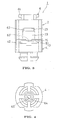
- FIGS. 1 through 13 show a first embodiment of the present invention.
- a hinge device 1 of this embodiment is used for turnably connecting, for example, a transmission section A and a reception section B of a cellular telephone shown in FIGS. 18 and 19.
- the hinge device 1 includes a first hinge member 2, a second hinge member 3, a hinge pin 6, a movable member 7 and a coiled spring (biasing means) 8.
- One of the first and second hinge members 2, 3 is non-turnably connected to the transmission section A and the other is non-turnably connected to the reception section B.
- the first hinge member 2 is non-turnably connected to the transmission section A
- the second hinge member 3 is non-turnably connected to the reception section B.
- first and second hinge members 2, 3 are turnably connected to each other through a hinge pin 6. Accordingly, the transmission section A and the reception section B are turnably connected to each other through the first and second hinge members 2, 3 and the hinge pin 6, i.e., through the hinge device 1.
- the first hinge member 2 is formed in a bottomed circular cylindrical configuration and has a through-hole (fitting hole) 22 of a circular configuration in section which is formed in a central part of its bottom part 21
- a pair of guide grooves 23, 23 extending in an axial direction of the first hinge member 2 are formed in an end part on the opening side of the first hinge member 2.
- the second hinge member 3 comprises a main body member 4 and a fixing member 5.
- a through-hole 41 passing through the main body member 4 is formed in a central part of the main body member 4.
- the main body member 4 is arranged opposite to the opening side end part of the first hinge member 2 with the axis of the through-hole 41 aligned with the axis of the through-hole 22 of the first hinge member 2.
- An engagement concave part 42 is formed in an opposing surface of the main body member 4 with respect to the first hinge member 2.
- the fixing member 5 is formed in a plate-like configuration as shown in FIGS. 1 through 5, 7 and 10.
- the fixing member 5 is non-turnably inserted in the engagement concave part 42.
- One end face 52 of the fixing member 5 is confronted with the first hinge member 2.
- the other end face of the fixing member 5 is abutted with a bottom surface of the engagement concave part 42.
- a through-hole 51 with its axis aligned with the axis of the through-hole 41 is formed in a central part of the fixing member 5.
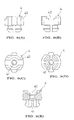
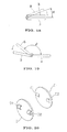
- the hinge pin 6 includes, as shown in FIGS. 5 and 7, a head part 61, an enlarged-diameter shaft part 62, a fixing shaft part 63 having a polygonal configuration in section, and a reduced-diameter shaft part 64.
- Those various parts each has a circular configuration in section excepting the fixing shaft part 63, and they are formed such that their axes are aligned with one another.
- the enlarged-diameter shaft part 62 is turnably inserted in the through-hole 22 of the first hinge member 2, and the head part 61 is abutted with the bottom part 21 of the first hinge member 2. Accordingly, the first hinge member 2 is non-movable with respect to the hinge pin 6 in a direction toward the bottom part 21 side from its opening side end part.
- the fixing shaft part 63 of the hinge pin 6 is non-turnably press-fitted in the through-hole 51 of the fixing member 5.
- the fixing member 5 is non-turnably connected to the hinge pin 6.
- the main body member 4 is also non-turnably connected to the hinge pin 6, and the second hinge member 3 is entirely non-turnably connected to the hinge pin 6.
- One end face 52 of the fixing member 5 facing the first hinge member 2 side is abutted with the end face of the enlarged-diameter shaft part 62 of the hinge pin 6. Accordingly, the second hinge member 3 is non-movably connected to the hinge pin 6 in a direction toward the head part 61 side.
- the reduced-diameter shaft part 64 of the hinge pin 6 is inserted in the through-hole 41 of the main body member 4.
- the main body member 4 is non-movably connected to the reduced-diameter shaft part 64 in a direction toward its tip side.
- the second hinge member 3 is connected to the hinge pin 6 such that the second hinge member 3 is non-movable in is axial direction and non-turnable. In other words, the second hinge member 3 is fixed to the hinge pin 6.
- the movable member 7 is, as shown in FIGS. 1 through 5, 7 and 11, arranged between the first hinge member 2 and the fixing member 5 of the second hinge member 5.
- the movable member 7 includes a flat plate part 71.
- a through-hole 72 passing through the flat plate part 71 is formed in a central part of the flat plate part 71.
- the enlarged-shaft part 62 of the hinge pin 6 is inserted in this through-hole 72 such that the enlarged-shaft part 62 is movable in its axial direction and turnable.
- Guide parts 73, 73 extending in parallel to the axis of the through-hole 72 are formed on one side part and the other side part of the flat plate part 71.
- the guide parts 73, 73 are inserted in the guide grooves 23, 23 of the first hinge member 2, respectively such that the guide parts 73, 73 are non-turnable but slidable.
- the movable member 7 is connected to the first hinge member 2 such that the movable member 7 is non-turnable but movable in the axial direction of the hinge pin 6.
- a coiled spring 8 is arranged between the inner peripheral surface of the first hinge member 2 and the outer peripheral surface of the enlarged-diameter shaft part 62 of the hinge pin 6.
- One end part of this coiled spring 8 is abutted with the bottom part 21 of the first hinge member 2, and the other end part is abutted with the flat plate part 71 of the movable member 7. Accordingly, the coiled spring 8 presses the first hinge member 2 against the head part 61 of the hinge pin 6 and biases the movable member 7 toward the second hinge member 3 side and presses the movable member 7 against one end face 52 of the fixing member 5.
- one end face 74 of the movable member 7 which is pressed against one end face 52 of the fixed member 5, is provided with a pair of convex parts 75, 75.
- the pair of convex parts 75, 75 are symmetrically arranged with respect to the through-hole 72.
- the convex part 75 extends in a direction orthogonal to the axis of the through-hole 72, and exhibits, as shown in FIG. 11(B), a semi-circular configuration when viewed in a direction orthogonal to the axis of the through-hole 72.
- the convex part 75 may be formed separately from the movable member 7.
- a spherical member is embedded in the movable member 7 with a part of the spherical member projecting from one end face 74 of the movable member 74 and a part of the spherical member projecting from one end face is formed in a convex part.
- one end face 52 of the fixing member 5 which is pressed against the movable member 7, is provided with a pair of concave parts 53, 53.
- the pair of concave parts 53, 53 are symmetrically arranged with respect to the axis of the through-hole 51.
- a bottom surface (cam face) 53a of the concave part 53 is constituted of an arcuate surface which is orthogonal to the axis of the through-hole 51, and the depth of the concave part 53 is set to be smaller than the radius of the annular surface which constitutes the bottom surface 53a.
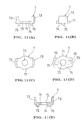
- the concave part 53 is arranged such that when the reception section B is located in a predetermined biasing angle range (hereinafter referred to as the "first biasing angle range") between the folding position and a position which is away therefrom by an angle ⁇ toward the using position side, the convex part 75 is abutted with the bottom surface 53a of the concave part 53. That is, when the reception section B is located in a position which is away by an angle ⁇ from the folding position, a place which is slightly away from the center of the convex part 75 is, as shown in FIG. 12, abutted with an intersection part between the bottom surface 53a and the end face 52.
- a predetermined biasing angle range hereinafter referred to as the "first biasing angle range”
- the second hinge member 3 is relatively turn-biased in the direction as indicated by the arrow with respect to the first hinge member 2 and thus, the reception section B is turn-biased toward the folding position. Then, the reception section B is turned to the folding position and held in that position.
- the convex part 75 When the reception section B is located in a position which is away by angle ⁇ from the folding position, the convex part 75 is located in a position which is laterally symmetric with the position shown in FIG. 12 with respect to the concave part 53, and when the reception section B is located in the using position, the convex part 75 is located in a position which is laterally symmetric with the position shown in FIG. 13 with respect to the concave part 53.
- the second biasing angle position when the reception section B is located in a predetermined biasing angle range (hereinafter referred to as the "second biasing angle position") between the position which is away by an angle ⁇ from the folding position and the using position, the biasing force of the coiled spring 8 is converted to a turn biasing force directing in a direction (the other direction) which is reverse to the direction indicated by the arrow of FIGS. 12 and 13.
- the reception section B is turned to the using position and held in the using position.
- the bottom surface 53a serving as a cam face may be an inclined planar surface or a convexly curved surface.
- a turn biasing mechanism 9 is constituted by a convex part 75 formed on the movable member 7, the bottom surface 53a of the concave part 53 formed in the fixing member 5 and the coiled spring 8.
- the angle obtained by subtracting the angle ⁇ from the angle formed between the transmission section A and the reception section B when the reception section B is located in the using position is set to be equal to the angle ⁇ . Those angles may be set to be different from each other.
- the outside diameter D is set to be larger, though slightly (for example, several ⁇ m), than the inside diameter d as expressed by D > d. Accordingly, the enlarged-diameter shaft part 62 is turnably press-fitted in the through-hole 22.
- a frictional resistance for preventing relative rotation between the first hinge member 2 and the hinge pin 6 is generated between the inner peripheral surface of the through-hole 22 and the outer peripheral surface of the enlarged-diameter shaft part 62.
- this frictional resistance acts as a turn resisting force for preventing relative rotation between the first hinge member 2 and the second hinge member 3.
- this turn resisting force is represented by F1
- the turn biasing force caused by the coiled spring 8 when the reception section B is located in the first biasing angle range is represented by F2
- the turn biasing force caused by the coiled spring 8 when the reception section B is located in the second biasing angle range is represented by F3
- the inside diameter d of the through-hole 22 and the outside diameter D of the enlarged-diameter shaft part 62 are determined such that the following expressions can be established.
- the turn biasing forces F2, F3 are actually obtained by subtracting the frictional resistance generated between the convex part 75 and the bottom surface 53a from the turn biasing force caused by the coiled spring and converted under the effect of the convex part 75 and the bottom surface 53a.
- the coiled spring 8 turn-biases the reception section B toward the folding position side or using position side with respect to the transmission section A.
- the frictional resistance acting between the inner peripheral surface of the through-hole 22 and the outer peripheral surface of the enlarged-diameter shaft part 62 prevents relative rotation of the reception section B with respect to the transmission section A. Since F1 ⁇ F2, F1 ⁇ F3 are established, the reception section B is turned to the folding position or using position by the coiled spring 8 and held in that position.
- the frictional resistance generated between the inner peripheral surface of the through-hole 22 of the first hinge member 2 and the outer peripheral surface of the enlarged-diameter shaft part 62 of the hinge pin 6 acts as a force for preventing relative rotation between the transmission section A and the reception section B, in addition to the frictional resistance generated between the convex part 75 of the movable member 7 and the end face 52 of the fixing member 5.
- the transmission section A and the reception section B can be stopped with force which is greater by a portion equal to the frictional resistance acting between the inner peripheral surface of the through-hole 22 and the outer peripheral surface of the hinge pin 6 compared with a case wherein the transmission section A and the reception section B are stopped only by the frictional resistance generated between the projection 75 and the end face 52.
- the transmission section A and the reception section B can stably be stopped.
- FIG. 14 shows a second embodiment of the present invention.
- the through-hole 22 of the first hinge member 2 is formed in a regular square configuration in section.
- the lengths of the respective sides of the through-hole 22 are set to be slightly smaller than the outside diameter of the enlarged-diameter shaft part 62.
- the enlarged-diameter shaft part 62 is press-fitted in the through-hole 22 and the outer peripheral surface of the enlarged-diameter shaft part 62 is press-contacted with the four sides of the through-hole 22.
- the reception section B is stably stopped in the stoppable range.
- FIG. 15 shows a third embodiment of the present invention.
- at least a part of the enlarged-diameter shaft part 62 fitted to the through-hole 22 is formed in a generally regular square configuration in section.
- An arcuate part 62a is formed on each of the four corner parts of that particular part of the enlarged-diameter shaft part 62.
- the interval between two arcuate parts 62a, 62a located on a diagonal line is set to be slightly larger than the inside diameter of the through-hole 22.
- the enlarged-diameter shaft part 62 is press-fitted in the through-hole 22 and the four arcuate parts 62a of the enlarged-diameter shaft part 62 are press-contacted with the inner peripheral surface of the through-hole 22.
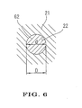
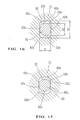
- FIGS. 16 and 17 show a fourth embodiment of the present invention.
- the through-hole 22 is formed in an elliptical configuration and it includes two parallel planar surface parts (first inner surface) 22a, 22a, and a pair of arcuate parts (second inner surface) 22b, 22b formed between the end parts of the planar surface parts 22a, 22a.
- the interval between the planar surface parts 22a, 22a is represented by W and the inside diameter of the arcuate parts 22b, 22b is represented by D1
- the interval W and the inside diameter D1 are set such that D1 > W is satisfied.
- the enlarged-diameter shaft part 62 is also formed in an elliptical configuration in section, and it includes mutually parallel two planar surface parts (outer surface) 62b, 62b and a pair of arcuate surface parts 62c, 62c formed between the end parts of the planar surface parts 62b, 62b.
- the interval between the planar surface parts 62b, 62b is set to be equal to the interval W between the planar surface parts 22a, 22a.
- the outside diameter D2 of the arcuate surfaces 62c, 62c is set to be slightly (about several ⁇ m) larger than the interval W but smaller than the inside diameter D1.
- the phase between the through-hole 22 and the enlarged-diameter shaft part 62 is determined such that when the reception section B is located in the folding position, as shown in FIG. 16, the planar surface parts 22a, 62b are mutually surface contacted, and when the reception section B is located in a position other than the folding position, as shown in FIG. 17, the arcuate surface 62c is contacted with the planar surface parts 22a.
- the phase between the through-hole 22 and the enlarged-diameter shaft part 62 may be determined such that in case the angle between the folding position and the using angle is represented by ⁇ ( ⁇ 180 degrees), the angle formed between the planar surface part 22a and the planar surface part 62b becomes (180 - ⁇ ) / 2 when the reception section B is located in the folding position.
- the phase between the through-hole 22 and the enlarged-diameter shaft part 62 when the reception section B is located in the folding position is symmetrical with the phase between the through-hole 22 and the enlarged-diameter part 62 when the reception section B is located in the using position with reference to a line bisecting the arcuate part 22b of the through-hole 22.
- the hinge device according to the present invention is used for a cellular telephone.
- the hinge device according to the present invention can likewise be applied to a notebook type personal computer, etc.
- the movable member 7 is connected to the first hinge member 2 such that the movable member 7 is non-turnable but movable.
- the movable member 7 may be connected to the second hinge member 3 such that the movable member 7 is non-turnable but movable.
- the movable member 7 is abutted with the first hinge member 2 by the coiled spring 8, and a convex part is formed on one of the abutment surfaces of the movable member 7 and the first hinge member 2, and a concave part whose bottom surface serves as a cam face is formed in the other abutment surface.
- the second hinge member 3 is constituted by the main body member 4 and the fixing member 5 which are separately formed. Instead, it is accepted that the main body member 4 and the fixing member 5 are integrally formed, and the second hinge member 3 is entirely integrated.
- the angle range between the folding position and a position which is away by an angle ⁇ from the folding position, and the angle range between a position which is away by an angle ⁇ from the folding position and the using position are referred to as the biasing angle range.
- the biasing angle range only one of the angle ranges may be referred to as the biasing angle range.
- a hinge device can be utilized as a hinge device for turnably connecting the transmission section and the reception section of a cellular telephone to each other or turnably connecting the keyboard section and the display section of a notebook type personal computer to each other.
Landscapes
- Engineering & Computer Science (AREA)
- Theoretical Computer Science (AREA)
- Computer Hardware Design (AREA)
- Physics & Mathematics (AREA)
- General Engineering & Computer Science (AREA)
- Human Computer Interaction (AREA)
- General Physics & Mathematics (AREA)
- Signal Processing (AREA)
- Mathematical Physics (AREA)
- Computer Networks & Wireless Communication (AREA)
- Pivots And Pivotal Connections (AREA)
- Telephone Set Structure (AREA)
- Hinge Accessories (AREA)
Applications Claiming Priority (3)
| Application Number | Priority Date | Filing Date | Title |
|---|---|---|---|
| JP2002158768A JP2003343543A (ja) | 2002-05-31 | 2002-05-31 | ヒンジ装置 |
| JP2002158768 | 2002-05-31 | ||
| PCT/JP2003/006364 WO2003102433A1 (en) | 2002-05-31 | 2003-05-21 | Hinge device |
Publications (2)
| Publication Number | Publication Date |
|---|---|
| EP1533532A1 true EP1533532A1 (de) | 2005-05-25 |
| EP1533532A4 EP1533532A4 (de) | 2006-06-28 |
Family
ID=29706494
Family Applications (1)
| Application Number | Title | Priority Date | Filing Date |
|---|---|---|---|
| EP03730554A Withdrawn EP1533532A4 (de) | 2002-05-31 | 2003-05-21 | Gelenkvorrichtung |
Country Status (7)
| Country | Link |
|---|---|
| US (1) | US7251859B2 (de) |
| EP (1) | EP1533532A4 (de) |
| JP (1) | JP2003343543A (de) |
| KR (1) | KR20050004259A (de) |
| CN (1) | CN100340779C (de) |
| TW (1) | TWI221888B (de) |
| WO (1) | WO2003102433A1 (de) |
Cited By (1)
| Publication number | Priority date | Publication date | Assignee | Title |
|---|---|---|---|---|
| CN1932316B (zh) * | 2005-09-16 | 2010-09-29 | 深圳富泰宏精密工业有限公司 | 多段式转轴结构 |
Families Citing this family (17)
| Publication number | Priority date | Publication date | Assignee | Title |
|---|---|---|---|---|
| JP4488490B2 (ja) * | 2004-01-09 | 2010-06-23 | スガツネ工業株式会社 | ヒンジ装置 |
| TWM264768U (en) * | 2004-06-18 | 2005-05-11 | Fih Co Ltd | Multi-segtion hinge mechanism |
| JPWO2005124168A1 (ja) * | 2004-06-22 | 2008-07-31 | 株式会社オーハシテクニカ | ヒンジ装置及びその取付け構造 |
| CN2745325Y (zh) * | 2004-11-06 | 2005-12-07 | 深圳富泰宏精密工业有限公司 | 铰链结构 |
| US7373693B2 (en) * | 2004-12-01 | 2008-05-20 | Illinois Tool Works Inc. | Hinge assembly |
| EP1908969A4 (de) * | 2005-07-08 | 2008-07-09 | Citizen Holdings Co Ltd | Scharniervorrichtung |
| US7681283B2 (en) * | 2005-07-12 | 2010-03-23 | Sugatsune Kogyo Co., Ltd. | Hinge assembly |
| US20070204437A1 (en) * | 2006-03-01 | 2007-09-06 | Hartmann Richard Jr | Folding assist handle assembly |
| US20080115325A1 (en) * | 2006-11-17 | 2008-05-22 | Shin Zu Shing Co., Ltd. | Dual-axis hinge assembly |
| US20080172836A1 (en) * | 2007-01-24 | 2008-07-24 | Shin Zu Shing Co., Ltd. | Positioning device for a laptop computer hinge |
| TW200848629A (en) * | 2007-06-11 | 2008-12-16 | Jarllytec Co Ltd | Revolving axle structure with position-locking engagement means |
| CN101338785B (zh) * | 2007-07-06 | 2010-12-01 | 深圳富泰宏精密工业有限公司 | 铰链结构及应用该铰链结构的便携式电子装置 |
| JP5134654B2 (ja) * | 2010-07-14 | 2013-01-30 | スガツネ工業株式会社 | ヒンジ装置 |
| KR101690794B1 (ko) * | 2010-10-11 | 2016-12-28 | 삼성전자주식회사 | 접이형 휴대 장치의 스냅 힌지 장치 |
| CN102840220A (zh) * | 2011-06-21 | 2012-12-26 | 鸿富锦精密工业(深圳)有限公司 | 铰链结构 |
| US11720144B2 (en) | 2021-11-29 | 2023-08-08 | Microsoft Technology Licensing, Llc | Hinged device |
| US12473763B2 (en) | 2022-08-23 | 2025-11-18 | Reell Precision Manufacturing Corporation | Detent hinge |
Family Cites Families (24)
| Publication number | Priority date | Publication date | Assignee | Title |
|---|---|---|---|---|
| US4043798A (en) * | 1974-09-20 | 1977-08-23 | Sumitomo Metal Industries Limited | Process for producing steel having improved low temperature impact characteristics |
| AU624027B2 (en) * | 1989-10-11 | 1992-05-28 | Sugatsune Industrial Co., Ltd | Door hinge |
| US5600868A (en) * | 1995-03-07 | 1997-02-11 | Santa Barbara Research Center | Deployment hinge |
| JPH10131947A (ja) * | 1996-10-28 | 1998-05-22 | Kato Electrical Mach Co Ltd | 複合トルクヒンジ |
| JP3818407B2 (ja) * | 1997-05-14 | 2006-09-06 | スガツネ工業株式会社 | 折り畳み式機器のカバーを広角度開閉保持可能としたヒンジ装置 |
| JP3732619B2 (ja) * | 1997-06-16 | 2006-01-05 | 加藤電機株式会社 | ヒンジ装置 |
| TW411069U (en) * | 1997-10-08 | 2000-11-01 | Kato Electric & Machinary Co | Hinge device |
| US6141831A (en) * | 1997-12-09 | 2000-11-07 | Cema Technologies, Inc. | Bistable hinge mechanism |
| JP3489668B2 (ja) * | 1999-05-31 | 2004-01-26 | スガツネ工業株式会社 | 折り畳み式機器の開閉保持用ヒンジ装置 |
| JP2001124051A (ja) * | 1999-10-21 | 2001-05-08 | Nifco Inc | フリーストップ装置 |
| JP2001317537A (ja) * | 2000-05-08 | 2001-11-16 | Sando Kogyosho:Kk | 小型機器用の回転抑制装置 |
| JP2001347537A (ja) * | 2000-06-08 | 2001-12-18 | Canon Inc | インサート部品、その成形方法およびプラスチック成形品 |
| JP3830745B2 (ja) * | 2000-09-29 | 2006-10-11 | スガツネ工業株式会社 | ヒンジ装置 |
| JP2001193727A (ja) | 2000-11-16 | 2001-07-17 | Sugatsune Ind Co Ltd | 折り畳み式機器の開閉保持用ヒンジ装置 |
| JP3647759B2 (ja) * | 2001-02-22 | 2005-05-18 | 株式会社ストロベリーコーポレーション | ヒンジ装置並びにヒンジ装置を用いた携帯式電子機器 |
| JP4290989B2 (ja) * | 2001-02-26 | 2009-07-08 | スガツネ工業株式会社 | ヒンジ装置 |
| JP4141651B2 (ja) * | 2001-02-28 | 2008-08-27 | スガツネ工業株式会社 | ヒンジ装置 |
| TW482229U (en) * | 2001-07-17 | 2002-04-01 | Hinge Basestrong Co Ltd | Rotating axle structure with lift and close function |
| JP2003120651A (ja) * | 2001-10-15 | 2003-04-23 | Ohashi Technica Inc | ヒンジ装置及びそれを用いた携帯電話機 |
| JP2003294026A (ja) * | 2002-04-03 | 2003-10-15 | Dcm:Kk | ヒンジ装置及びヒンジ装置を備えた携帯情報機器 |
| JP2004176780A (ja) * | 2002-11-26 | 2004-06-24 | Heiwa Tokei Mfg Co Ltd | ヒンジ装置 |
| JP2004213981A (ja) * | 2002-12-27 | 2004-07-29 | Staf Corp | スイッチ機構 |
| US7027294B2 (en) * | 2003-12-05 | 2006-04-11 | Katoh Electrical Machinery Co., Ltd. | Hinge for electronic equipment and electronic equipment using the same |
| CN103929314A (zh) * | 2013-01-12 | 2014-07-16 | 陕西天思信息科技有限公司 | 一种多模接入的新型eoc设备 |
-
2002
- 2002-05-31 JP JP2002158768A patent/JP2003343543A/ja active Pending
-
2003
- 2003-05-21 WO PCT/JP2003/006364 patent/WO2003102433A1/ja not_active Ceased
- 2003-05-21 KR KR10-2004-7019351A patent/KR20050004259A/ko not_active Ceased
- 2003-05-21 CN CNB038126540A patent/CN100340779C/zh not_active Expired - Fee Related
- 2003-05-21 US US10/516,064 patent/US7251859B2/en not_active Expired - Fee Related
- 2003-05-21 EP EP03730554A patent/EP1533532A4/de not_active Withdrawn
- 2003-05-28 TW TW092114369A patent/TWI221888B/zh not_active IP Right Cessation
Cited By (1)
| Publication number | Priority date | Publication date | Assignee | Title |
|---|---|---|---|---|
| CN1932316B (zh) * | 2005-09-16 | 2010-09-29 | 深圳富泰宏精密工业有限公司 | 多段式转轴结构 |
Also Published As
| Publication number | Publication date |
|---|---|
| TWI221888B (en) | 2004-10-11 |
| WO2003102433A1 (en) | 2003-12-11 |
| JP2003343543A (ja) | 2003-12-03 |
| TW200400328A (en) | 2004-01-01 |
| KR20050004259A (ko) | 2005-01-12 |
| HK1079269A1 (en) | 2006-03-31 |
| CN100340779C (zh) | 2007-10-03 |
| CN1659386A (zh) | 2005-08-24 |
| US7251859B2 (en) | 2007-08-07 |
| US20050160557A1 (en) | 2005-07-28 |
| EP1533532A4 (de) | 2006-06-28 |
Similar Documents
| Publication | Publication Date | Title |
|---|---|---|
| US7251859B2 (en) | Hinge device | |
| US6990711B2 (en) | Hinge device and cell phone | |
| EP1182316A1 (de) | Scharniervorrichtung | |
| US6785936B2 (en) | Hinge device | |
| US7484271B2 (en) | Device case opening/closing device, and 2-axis hinge device | |
| JP3830746B2 (ja) | ヒンジ装置 | |
| EP1365639B1 (de) | Schwenkeinrichtung | |
| US20080078058A1 (en) | Hinge assembly and foldable electronic device using the same | |
| US7047599B2 (en) | Hinge assembly | |
| EP1321684B1 (de) | Gelenk | |
| US6587676B1 (en) | Hinge assembly | |
| US7386918B2 (en) | Hinge device | |
| EP1767796A1 (de) | Zweiachsige scharniervorrichtung | |
| JP4373852B2 (ja) | ヒンジ装置 | |
| EP1445501A1 (de) | Gelenkvorrichtung und dieses gelenk verwendendes faltbares mobiltelefon | |
| JP4660892B2 (ja) | 開閉装置 | |
| JP2003003722A (ja) | 回転規制機構付きヒンジ | |
| HK1079269B (en) | Hinge device |
Legal Events
| Date | Code | Title | Description |
|---|---|---|---|
| PUAI | Public reference made under article 153(3) epc to a published international application that has entered the european phase |
Free format text: ORIGINAL CODE: 0009012 |
|
| 17P | Request for examination filed |
Effective date: 20041222 |
|
| AK | Designated contracting states |
Kind code of ref document: A1 Designated state(s): AT BE BG CH CY CZ DE DK EE ES FI FR GB GR HU IE IT LI LU MC NL PT RO SE SI SK TR |
|
| RBV | Designated contracting states (corrected) |
Designated state(s): DE FI FR GB NL |
|
| A4 | Supplementary search report drawn up and despatched |
Effective date: 20060531 |
|
| 17Q | First examination report despatched |
Effective date: 20070518 |
|
| GRAJ | Information related to disapproval of communication of intention to grant by the applicant or resumption of examination proceedings by the epo deleted |
Free format text: ORIGINAL CODE: EPIDOSDIGR1 |
|
| GRAP | Despatch of communication of intention to grant a patent |
Free format text: ORIGINAL CODE: EPIDOSNIGR1 |
|
| STAA | Information on the status of an ep patent application or granted ep patent |
Free format text: STATUS: THE APPLICATION IS DEEMED TO BE WITHDRAWN |
|
| 18D | Application deemed to be withdrawn |
Effective date: 20100127 |