EP1533528A2 - Procédé de fabrication d'un rotor pour pompes centrifuges - Google Patents
Procédé de fabrication d'un rotor pour pompes centrifuges Download PDFInfo
- Publication number
- EP1533528A2 EP1533528A2 EP04105337A EP04105337A EP1533528A2 EP 1533528 A2 EP1533528 A2 EP 1533528A2 EP 04105337 A EP04105337 A EP 04105337A EP 04105337 A EP04105337 A EP 04105337A EP 1533528 A2 EP1533528 A2 EP 1533528A2
- Authority
- EP
- European Patent Office
- Prior art keywords
- edges
- rear cover
- facing away
- cover plate
- blades
- Prior art date
- Legal status (The legal status is an assumption and is not a legal conclusion. Google has not performed a legal analysis and makes no representation as to the accuracy of the status listed.)
- Ceased
Links
Images

Classifications
-
- B—PERFORMING OPERATIONS; TRANSPORTING
- B23—MACHINE TOOLS; METAL-WORKING NOT OTHERWISE PROVIDED FOR
- B23P—METAL-WORKING NOT OTHERWISE PROVIDED FOR; COMBINED OPERATIONS; UNIVERSAL MACHINE TOOLS
- B23P15/00—Making specific metal objects by operations not covered by a single other subclass or a group in this subclass
- B23P15/006—Making specific metal objects by operations not covered by a single other subclass or a group in this subclass turbine wheels
-
- F—MECHANICAL ENGINEERING; LIGHTING; HEATING; WEAPONS; BLASTING
- F04—POSITIVE - DISPLACEMENT MACHINES FOR LIQUIDS; PUMPS FOR LIQUIDS OR ELASTIC FLUIDS
- F04D—NON-POSITIVE-DISPLACEMENT PUMPS
- F04D29/00—Details, component parts, or accessories
- F04D29/18—Rotors
- F04D29/22—Rotors specially for centrifugal pumps
- F04D29/2205—Conventional flow pattern
- F04D29/2222—Construction and assembly
-
- B—PERFORMING OPERATIONS; TRANSPORTING
- B29—WORKING OF PLASTICS; WORKING OF SUBSTANCES IN A PLASTIC STATE IN GENERAL
- B29L—INDEXING SCHEME ASSOCIATED WITH SUBCLASS B29C, RELATING TO PARTICULAR ARTICLES
- B29L2031/00—Other particular articles
- B29L2031/08—Blades for rotors, stators, fans, turbines or the like, e.g. screw propellers
- B29L2031/087—Propellers
Definitions
- Impellers for centrifugal pumps are known. In “Basics for the planning of centrifugal pump systems, Fritz Brüchler, Dennis Carter, Peter Fandray, Jan Fischer, Ralf Mann, 7. revised and expanded edition 2000, Sterling SIHI GmbH, page 44 "is based on different impeller shapes pointed. This is how you differentiate, for example, radial wheels and semi-axial wheels. Often there are wheels for Centrifugal pumps from a rear cover disc and a front shroud, between which shovels for that too promoting medium are arranged. For series production is a manufacture of such wheels, for many uses advantageously consist of plastic, through the Injection molding particularly desirable, but not what is possible. The reason lies in the relatively constructive elaborate design of the rear cover, the front cover plate and in particular the between these two arranged blades. This constructive Design complicates the extension of the injection molds The impeller thus produced, or makes it completely impossible.
- the invention is therefore based on the object, a method for producing an impeller for a centrifugal pump create, where possible, the largest possible Mass portion of the impeller as a single part in a spray - or casting process.
- the object underlying the invention is achieved by a Process for producing an impeller for a Centrifugal pump solved, in which a first part, from the rear cover plate with connection piece for the drive consists, at the side facing away from the connector Shovels are arranged at their, the rear Cover disc opposite edges at least partially with a Approach associated with part of the front Cover disc represents and the at its, the longitudinal axis running outer surface is cylindrically limited, wherein the Outer diameter D the inner diameter of the suction nozzle corresponds, in a spraying or casting process as Item is made and then a second one Part that covers the remaining part of the front cover represents and annular with an inner diameter, the corresponds to the outer diameter D, is formed on the Approach of the first part is deferred until it reaches the still freestanding areas of the rear cover disk facing away from edges of the blades and finally with the approach or the edges of the blades is connected.
- impeller are radial or semi-axial Understanding impellers for centrifugal pumps.
- the connection piece for the drive is usually in the form of a pipe socket educated.
- the blades are, at their, the rear Cover disc opposite edges at least partially with a Approach connected, with the connection in the middle area he follows. This means that the edges run outward are exposed, thus not in their outer area with connected to the approach.
- the outer diameter D corresponds the inner diameter of the suction nozzle and the Inner diameter of the second part, of course, underneath to understand that the corresponding tolerances, the on the one hand are required, the first part in the Introduce suction and on the other hand, the second part to defer the first part must be respected.
- the second part is also sprayed or cast produced.
- Both the first part and the second part Can be made of plastic or a metallic material exist, whereby the plastic for many purposes of the Impeller is the preferred material.
- the second part is designed annular, but usually a conical course, especially the outer surface of the second Part, is striven for aerodynamic reasons.
- the Connecting the first part with the second part can for example, by gluing done. It is in the Usually possible to connect to the neck or the edges or with both the neck and the edges too realize. It has turned out surprisingly that deals with the process of making an impeller for a centrifugal pump almost the whole impeller after the Spraying or casting process can be manufactured as a single part. This can usually be done in a single step respectively.
- the second part before putting off on the approach of the first Part provided with grooves, which are still free-standing Areas of the rear cover plate facing away from the edges Shovels are formed complementarily and each edge when Sliding the second part into a groove.
- grooves are still free-standing Areas of the rear cover plate facing away from the edges Shovels are formed complementarily and each edge when Sliding the second part into a groove.
- the grooves should be understood that they have a shape corresponding to the curved shape of the Correspond to edges of the blades, so that these edges too can be suitably inserted into the respective grooves.
- the first part is connected to the second part by welding.
- the first part and the second part Made of plastic are the Laser or ultrasonic welding as a welding process.
- Consist of the first part and the second part of weldable Metals or metal compounds, so joining can particularly preferably be carried out by resistance welding.
- a particularly advantageous fixed connection reached the first part with the second part, so that the Impeller for a centrifugal pump for a relatively large number suitable for applications.
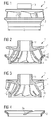
- Fig. 1 the impeller, which according to the method for Production of an impeller made for a centrifugal pump was shown in the side view.
- the impeller points a first part 1, which consists of the rear cover plate 1 " with connection piece 1a for the drive.
- This approach 1 ' forms part of the He is at his, the longitudinal axis encircling outer surface cylindrically limited, wherein the Outer diameter D the inner diameter of the suction nozzle (not shown) corresponds.
- the first part 1 will be in made by injection or casting as a single part.
- the impeller further comprises a second part 2, which the represents remaining part of the front cover plate and circular with an inside diameter corresponding to the Outer diameter D corresponds, is formed.
- the second part 2 of the procedure is the approach 1 'of the first Part 1 is postponed until it is still on freestanding areas the rear cover disc 1 "facing away from edges (not shown) of the blades 1 * is present. Then done a connection of the first part 1 with the second part 2.
- the impeller is shown in longitudinal section.
- the first part 1 is provided with blades 1 *, which at their, the Rear cover disc 1 "opposite edges 1b at least partially connected to a lug 1 '. Stick to it the outer areas of the rear cover disc 1 " facing away edges 1b exposed, so are not with the Approach 1 'connected.
- the second part 2 will be before the Sliding on the approach 1 'of the first part 1 with grooves 2 a provided to the still free-standing areas of the rear cover plate 1 "opposite edges 1b of the blades 1 * are formed complementary. So every edge 1b is at Sliding the second part 2 introduced into a groove 2a.
- the first part 1 according to FIG. 2 in longitudinal section shown. Compared to the second part (not shown), the first part 1 is the largest mass share of the impeller, in the injection or casting process as Item can be manufactured, with an extension of the Injection tools (not shown) from the finished manufactured first part 1 is easily possible.
- the second part 2 of the impeller is in longitudinal section shown in FIG. 2. It is circular with outside formed conical shape and has a Inner diameter, the outer diameter D of FIG. 1 equivalent. It goes without saying that appropriate tolerances are met, so that a Sliding the second part 2 on the first part (not shown) is possible.
- FIG. 5 is a plan view of the first part 1 of Impeller with a direct view of the approach 1 'shown. It becomes clear that the outer areas of the rear cover disc 1 "away from edges 1b, that is not connected to the approach 1 '.
- Connector 1a is usually one Pipe fittings.
- the chuck piece 1 a as annular stiffening of the rear cover disc 1 " train.
Landscapes
- Engineering & Computer Science (AREA)
- Mechanical Engineering (AREA)
- General Engineering & Computer Science (AREA)
- Structures Of Non-Positive Displacement Pumps (AREA)
Applications Claiming Priority (2)
| Application Number | Priority Date | Filing Date | Title |
|---|---|---|---|
| DE10354750 | 2003-11-21 | ||
| DE2003154750 DE10354750A1 (de) | 2003-11-21 | 2003-11-21 | Verfahren zur Herstellung eines Laufrades für eine Kreiselpumpe |
Publications (2)
| Publication Number | Publication Date |
|---|---|
| EP1533528A2 true EP1533528A2 (fr) | 2005-05-25 |
| EP1533528A3 EP1533528A3 (fr) | 2009-07-29 |
Family
ID=34428871
Family Applications (1)
| Application Number | Title | Priority Date | Filing Date |
|---|---|---|---|
| EP20040105337 Ceased EP1533528A3 (fr) | 2003-11-21 | 2004-10-27 | Procédé de fabrication d'un rotor pour pompes centrifuges |
Country Status (2)
| Country | Link |
|---|---|
| EP (1) | EP1533528A3 (fr) |
| DE (1) | DE10354750A1 (fr) |
Cited By (3)
| Publication number | Priority date | Publication date | Assignee | Title |
|---|---|---|---|---|
| EP2402112A3 (fr) * | 2010-06-29 | 2012-09-26 | Turbocam, Inc. | Procédé de production de turbine carénée à partir d'au moins deux composants |
| DE102016217110A1 (de) | 2016-09-08 | 2018-03-08 | KSB SE & Co. KGaA | Kreiselpumpe |
| CN117189661A (zh) * | 2022-05-30 | 2023-12-08 | 格兰富控股公司 | 离心泵注塑叶轮及离心泵 |
Families Citing this family (1)
| Publication number | Priority date | Publication date | Assignee | Title |
|---|---|---|---|---|
| EP2143957B2 (fr) † | 2008-07-10 | 2016-08-10 | Grundfos Management A/S | Composant d'écoulement d'une pompe |
Family Cites Families (9)
| Publication number | Priority date | Publication date | Assignee | Title |
|---|---|---|---|---|
| DE611356C (de) * | 1933-06-01 | 1935-03-26 | Giesserei & Maschinenfabrik Og | Kreiselpumpenlaufrad |
| GB537727A (en) * | 1940-04-03 | 1941-07-03 | Coventry Climax Eng Ltd | Improvements in centrifugal pumps |
| FI54186C (fi) * | 1976-05-11 | 1978-10-10 | Sarlin Ab Oy E | Loephjul |
| JPS5888497A (ja) * | 1981-11-18 | 1983-05-26 | Matsushita Electric Ind Co Ltd | ポンプ用羽根車 |
| DE3611910A1 (de) * | 1986-04-09 | 1987-10-15 | Schaeffler Waelzlager Kg | Laufrad fuer eine radialpumpe |
| JP2757511B2 (ja) * | 1989-12-25 | 1998-05-25 | 松下電器産業株式会社 | 送風機用インペラの製造方法 |
| FR2703111B1 (fr) * | 1993-03-25 | 1995-06-30 | Ozen Sa | Rotor pour pompe comportant deux pieces assemblees par soudure, obtenues par moulage par injection de materiaux thermoplastiques, et procede de fabrication d'un tel rotor . |
| DE19701297A1 (de) * | 1997-01-16 | 1998-07-23 | Wilo Gmbh | Laufrad einer Kreiselpumpe |
| DE19742023B4 (de) * | 1997-09-24 | 2006-07-13 | Beez, Günther, Dipl.-Ing. | Laufrad |
-
2003
- 2003-11-21 DE DE2003154750 patent/DE10354750A1/de not_active Withdrawn
-
2004
- 2004-10-27 EP EP20040105337 patent/EP1533528A3/fr not_active Ceased
Cited By (5)
| Publication number | Priority date | Publication date | Assignee | Title |
|---|---|---|---|---|
| EP2402112A3 (fr) * | 2010-06-29 | 2012-09-26 | Turbocam, Inc. | Procédé de production de turbine carénée à partir d'au moins deux composants |
| US8727729B2 (en) | 2010-06-29 | 2014-05-20 | Turbocam, Inc. | Method for producing a shrouded impeller from two or more components |
| DE102016217110A1 (de) | 2016-09-08 | 2018-03-08 | KSB SE & Co. KGaA | Kreiselpumpe |
| WO2018046405A1 (fr) | 2016-09-08 | 2018-03-15 | Ksb Aktiengesellschaft | Pompe centrifuge |
| CN117189661A (zh) * | 2022-05-30 | 2023-12-08 | 格兰富控股公司 | 离心泵注塑叶轮及离心泵 |
Also Published As
| Publication number | Publication date |
|---|---|
| DE10354750A1 (de) | 2005-06-23 |
| EP1533528A3 (fr) | 2009-07-29 |
Similar Documents
| Publication | Publication Date | Title |
|---|---|---|
| DE2046486C3 (de) | Schaufelrad für Lüfter | |
| EP2439056B1 (fr) | Procédé de fabrication d'une pièce décorative et une telle pièce décorative | |
| DE102005019685A1 (de) | Emblem für ein Kraftfahrzeug | |
| EP1777439A1 (fr) | Roue dentée et procédé de fabrication associée | |
| DE19701297A1 (de) | Laufrad einer Kreiselpumpe | |
| EP1636474A2 (fr) | Procede de production d'un piston monobloc pour un moteur a combustion | |
| EP1533528A2 (fr) | Procédé de fabrication d'un rotor pour pompes centrifuges | |
| DE19742023B4 (de) | Laufrad | |
| WO2009065894A1 (fr) | Roue de compresseur d'un compresseur centrifuge radial et procédé pour produire une telle roue de compresseur | |
| DE102007055616A1 (de) | Verdichterrad eines Radialverdichters und Verfahren zur Herstellung eines solchen Verdichterrades | |
| EP2369070B1 (fr) | Régulateur de rayon ou élément de sortie sanitaire analogue ainsi que procédé et outil de coulée par injection destinés à sa fabrication | |
| EP1533104B1 (fr) | Procédé de fabrication d'un rotor pour une pompe centrifuge | |
| DE10359854A1 (de) | Zylinderkopfbohrer mit Hartmetallschneiden und Kunststoffschaft | |
| EP3976337B1 (fr) | Pièce moulée par injection et procédé pour la fabrication de la pièce moulée par injection | |
| DE1909530A1 (de) | Abstreifer-Manschette | |
| DE602004008858T2 (de) | Hydraulikaggregrat für eine blockiergeschützte Fahrzeugbremsanlage und Verfahren zu dessen Herstellung | |
| DE19833314C2 (de) | Verfahren zum Herstellen eines Lenkrades | |
| DE19707557B4 (de) | Schaufelrad für eine von einem Medium durchströmte Maschine | |
| DE102007010769A1 (de) | Felge sowie Verfahren zum Herstellen einer Felge | |
| WO1996018820A1 (fr) | Fixation de rotor | |
| DE102013104534A1 (de) | Laufrad sowie Segment zu dessen Herstellung und Herstellungsverfahren für das Laufrad | |
| DE19615309B4 (de) | Verfahren, spritzgegossener Körper und Spritzgießform zur Herstellung eines spritzgegossenen Körpers | |
| WO1985001480A1 (fr) | Enjoliveur et son procede de fabrication | |
| EP4305315A1 (fr) | Fabrication d'une roue à aubes dans un procédé hybride | |
| DE1935013A1 (de) | Laufrad fuer Axial-Luefter |
Legal Events
| Date | Code | Title | Description |
|---|---|---|---|
| PUAI | Public reference made under article 153(3) epc to a published international application that has entered the european phase |
Free format text: ORIGINAL CODE: 0009012 |
|
| AK | Designated contracting states |
Kind code of ref document: A2 Designated state(s): AT BE BG CH CY CZ DE DK EE ES FI FR GB GR HU IE IT LI LU MC NL PL PT RO SE SI SK TR |
|
| AX | Request for extension of the european patent |
Extension state: AL HR LT LV MK |
|
| RAP1 | Party data changed (applicant data changed or rights of an application transferred) |
Owner name: CONTINENTAL AUTOMOTIVE GMBH |
|
| PUAL | Search report despatched |
Free format text: ORIGINAL CODE: 0009013 |
|
| AK | Designated contracting states |
Kind code of ref document: A3 Designated state(s): AT BE BG CH CY CZ DE DK EE ES FI FR GB GR HU IE IT LI LU MC NL PL PT RO SE SI SK TR |
|
| AX | Request for extension of the european patent |
Extension state: AL HR LT LV MK |
|
| 17P | Request for examination filed |
Effective date: 20100129 |
|
| AKX | Designation fees paid |
Designated state(s): DE ES FR GB IT |
|
| 17Q | First examination report despatched |
Effective date: 20100316 |
|
| STAA | Information on the status of an ep patent application or granted ep patent |
Free format text: STATUS: THE APPLICATION HAS BEEN REFUSED |
|
| 18R | Application refused |
Effective date: 20110629 |