EP1533149B1 - Attelage pour vehicules - Google Patents
Attelage pour vehicules Download PDFInfo
- Publication number
- EP1533149B1 EP1533149B1 EP04023640A EP04023640A EP1533149B1 EP 1533149 B1 EP1533149 B1 EP 1533149B1 EP 04023640 A EP04023640 A EP 04023640A EP 04023640 A EP04023640 A EP 04023640A EP 1533149 B1 EP1533149 B1 EP 1533149B1
- Authority
- EP
- European Patent Office
- Prior art keywords
- ball
- head
- bearing
- trailer coupling
- coupling according
- Prior art date
- Legal status (The legal status is an assumption and is not a legal conclusion. Google has not performed a legal analysis and makes no representation as to the accuracy of the status listed.)
- Expired - Lifetime
Links
Images


Classifications
-
- B—PERFORMING OPERATIONS; TRANSPORTING
- B60—VEHICLES IN GENERAL
- B60D—VEHICLE CONNECTIONS
- B60D1/00—Traction couplings; Hitches; Draw-gear; Towing devices
- B60D1/24—Traction couplings; Hitches; Draw-gear; Towing devices characterised by arrangements for particular functions
- B60D1/26—Traction couplings; Hitches; Draw-gear; Towing devices characterised by arrangements for particular functions for remote control, e.g. for releasing
-
- B—PERFORMING OPERATIONS; TRANSPORTING
- B60—VEHICLES IN GENERAL
- B60D—VEHICLE CONNECTIONS
- B60D1/00—Traction couplings; Hitches; Draw-gear; Towing devices
- B60D1/01—Traction couplings or hitches characterised by their type
- B60D1/06—Ball-and-socket hitches
-
- B—PERFORMING OPERATIONS; TRANSPORTING
- B60—VEHICLES IN GENERAL
- B60D—VEHICLE CONNECTIONS
- B60D1/00—Traction couplings; Hitches; Draw-gear; Towing devices
- B60D1/48—Traction couplings; Hitches; Draw-gear; Towing devices characterised by the mounting
- B60D1/54—Traction couplings; Hitches; Draw-gear; Towing devices characterised by the mounting collapsible or retractable when not in use, e.g. hide-away hitches
Definitions
- the invention relates to a towing hitch for motor vehicles, comprising a fixed vehicle, pivotally mounted via a path control and axially displaceable ball rod, which carries a coupling ball at its free end and both in its rest position and in its operating position via engageable form-fitting contours on the one hand a ball rod bearing head and on the other hand, a rotationally fixed this opposite component is fixable.
- a hitch with a rotary pivoting movement of the ball bar causing web control is from the EP 1 084 871 A2 known.
- a sleeve receiving the ball rod has a linear guide slot and with this branched branch slots. In the guide slot engages at the remote from the coupling ball end firmly connected to the ball rod guide pin. As soon as the guide pin reaches a branching slot, a rotational movement of the ball rod is superimposed on the axial movement.
- the axial adjustment is initiated by a motor which acts on a arranged in an axial bore of the ball rod, central adjusting spindle
- this known ball bar is an adjustable, the bearing sleeve or the ball rod bearing head abutment abutment, which is arranged as the ball rod bearing head on a bearing pin, which is attached via a mounting lug or mounting flange on a cross-tube connected to the vehicle.
- the bearing sleeve supporting abutment In one axial position of the bearing sleeve supporting abutment are the form-fitting contours of bearing pin and bearing sleeve so engaged that the bearing sleeve and thus the ball bar against the vehicle can not be rotated.
- the bearing sleeve In the second axial position, in which the abutment is then removed from the attachment lug, the bearing sleeve can be moved so far that the form-fitting contours are disengaged, whereupon the bearing sleeve together with ball bar arranged between the rest and the operating position can be pivoted. The respective locking position is then achieved by a renewed axial displacement of the abutment.
- trailer hitches which have for locking and releasing the ball bar a lock, which has a against a pending force element, in particular a compression spring, via an actuatable from the outside pressure or traction locking pin, the radially engageable and disengageable locking means, in particular balls , are assigned, as from the DE-U 94 08 478.5 known.
- the biasing of the compression spring takes place here by means of a handwheel, which operates a rack as a connection to the locking pin.
- the ball bar itself is formed as part of a spindle of a spindle-nut drive and axially adjustable. It has a screwed adjusting spindle, which is rotated via a spur and planetary gear by an electric motor.
- the ball rod is arranged in a guide sleeve, which is formed with a positive guide and causes after a guided axial displacement, the ball rod is then rotated in its operating position upwardly pointing ball.
- hitch has only a single, obliquely oriented pivot axis for the movement of the ball rod. This requires because of the spatial inclination of the pivot axis a large space and also a large free space for movement, which is not available for many vehicles. From the WO-A1-03 / 072375 a hitch with a mechanical motion drive is known in which the ball rod is mounted movably about two rotational axes aligned with each other at right angles.
- the invention has for its object to provide a generic, largely maintenance-free towing hitch, which allows pivoting (motor or by hand) of the ball rod arbitrary and variable pivoting movements, in particular to pivot the ball bar with the least possible movement space in a non-visible inoperative position; In addition, an automatic axial displacement of the ball rod to be made possible.
- the ball rod bearing head is arranged on a pivoting of the ball rod from the one to the other end position movements about a changing point in space causing swash bearing with a path control of Kugelstangeniagerkopfes and that the swash bearing is arranged on a hollow shaft, which is formed with a centrally integrated axially acting locking of the ball rod bearing head for engaging the positive locking contours both in the operating position and in the rest position of the ball rod. It can thus be achieved that the pivoting movements are no longer dependent on axes of rotation, as in space oblique axes of rotation.
- the ball bar After the axial or axial axial displacement of the ball bar, which requires only a small amount of axial displacement to disengage the positive locking contours, the ball bar can be moved with an almost linear movement, i. largely in each position the same distance to the rear of the vehicle or rear end sheet metal swing by hand or motor to pivot into its final position and then be locked again.
- the swash bearing is inventively arranged on a hollow shaft, which is formed centrally integrated with an axially acting locking of the ball rod bearing head for engaging the positive locking contours both in the operating position and in the rest position of the ball rod.
- the axially acting lock also allows a simultaneous automatic forced displacement of the ball bar, as soon as the blocking or locking is released in a rotary end position.
- An embodiment of the invention provides that the swash bearing has a ball head, the interposition of a bearing ring in a half-shell-like Housing of the ball rod bearing head is arranged. After triggering the locking or form-locking connection and the concomitant axial displacement or displacement of the ball-rod bearing head, this can pivot with the path control predetermined, optimized movement pattern on the ball head.
- the swash bearing has a spherical bearing ring which - optionally via a complementary spherical intermediate ring - carries the ball rod bearing head.
- the ball bar rotating around the bearing ring here can perform large wobble angles.
- the Kugeistangenlagerkopf spherical form and in a curved component for. B. a pot-like rotary part or a connecting plate, arrange.
- a required for attachment to a base support of the vehicle connection plate can thus already take up the same ball bearing head, wherein the positive locking contours, z. B. balls and calottes or teeth and counter teeth, on the one hand in the ball rod bearing head and on the other hand in the curvature of the component or in particular connecting plate are provided.
- Embodiments of the invention provide that the hollow shaft is arranged in the connecting plate or is integrally formed with this up to the ball head continuing. In the latter case, so to speak, there is a hollow ball pin.
- the lock comprises a guided in the hollow shaft, against a pending force element via an actuatable from the outside pressure or traction means locking pin and cooperating with this, arranged in radial bores of the hollow shaft, one and disengageable locking means.
- the locking pin presses the locking means, for.
- balls, pins or the like in the radial bores outwardly into the bearing ring and thus prevents axial displacement of the ball rod. If then the force element, for.
- a compression spring is biased or contracted, for example by means of a handwheel, as from the already mentioned DE-U 94 084 785 known, so that the locking pin is withdrawn, fall the previously pressed apart locking means inside. They then lie down in front of the head of the locking pin and prevent the locking pin from being able to move axially forward from its retracted position.
- the ball rod comes out of its form-locking connection and can thus swing under unlocking, under gravity with simultaneous axial displacement in an intermediate position. From this out, it can be manually or motor-driven pivot into the desired, each secured by an outer stop rotational end position and re-lock what the power element relaxation is enabled so that the locking pin advance and the locking means can push outward again into its locking position.
- the axial movement of another solenoid can lock as a backup.
- the securing lifting magnet and subsequently the main magnet are released via a controller.
- the web control is designed as a backdrop with engaging thereon followers.
- a path control with interlocking parts such as a slide and following means (pin, bolt or the like)
- sliding or sliding components can be provided on each other.
- the backdrop is formed as a radial groove in the ball head with on one ball half to the other ball half opposite direction course of the Nutbahnen and the following means are diametrically opposed to each other in a ball rod bearing head provided in the retaining ring arranged pins.
- the Nutbahnen give the ball bar on the engaging pins or the like guide elements or followers both the pivoting or tumbling around the hollow ball and the spherical bearing ring and the engagement and disengagement, i. the axial displacement by a few millimeters, exactly before.
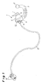
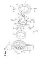
- FIG. 1 Trailer coupling 1 shown is attached via a one or more parts cross member to a vehicle (not shown).
- the hitch 1 includes in the embodiment a cranked, at its free end a coupling ball 2 supporting ball bar 3, which is arranged with its ball rod bearing head 4 here between a mounting flange 5 and an opposite with the interposition of a shim 6 connecting plate 7.
- the holder of the ball rod bearing head by means of a hollow shaft 8 and 108 (see Fig. 2 to 13 or 14) on which the ball rod is arranged with its ball rod bearing head.
- the ball rod can be closed at one end by end caps or sleeves and only a component, possibly including a gusset plate attached.
- a mounting bush which is inserted from the outside of the mounting flange 5 forth in a centered bore with respect to the hollow shaft with a hub, wherein the central bore of the outer side of the mounting flange 5 is overhanged by a flange of the mounting bush, so that through the flange 12 screwed into a collar of the hollow shaft mounting screws 14 provide for an exact positioning of the hollow shaft.
- the ball rod 3 is locked as rotatably as in their in Fig. 9 after rest in the other rotational end position shown rest position.
- a handwheel release mechanism 16 connected via a Bowden cable 17, at its in the ball rod bearing head 4 immersed end with a in the hollow shaft 8 and 108 movable back and forth locking pin 18 (see Fig. 13 and 14 ) connected is.
- the ball rod 3 via a Formschiusstress 19, which consists of balls 20 and these oppositely associated calotte 21, rotatably fixed.
- the swash bearing 23 in the FIGS. 2 to 10 shown ball bar 3 is in detail the FIG. 11 combined with FIG. 12 refer to.
- the ball head 22 of the swash bearing 23 is formed integrally with the hollow shaft 8 and arranged with the interposition of a bearing ring 27 in a half-shell-like housing of the ball bearing head 4.
- a path control 28 is provided, in the form of a link 29 in the ball head 22 as a circumferential radial groove 30 with on one ball half against the other ball half opposite direction of the Nutbahnen 31st a or 31 b (cf. FIG. 12 II and III) is incorporated.
- the path control 128 has the following means 133 or guide elements in the curved connecting plate 24, to which a set 129 with a funnel-shaped recess 129 is assigned in the spherical ball-and-socket bearing head 104.
- the receptacles 40 may be provided on their facing in the locking direction running surface with a run-on slope, which cause a selectively aligned force for axial displacement of the ball bar 3 and the ball rod bearing head 4 in the locking direction when tightening the ball bar 3 in the locked position in the rotary end positions.
- the locking pin 18, which is formed at its the balls 39 through the radial bores 37 and 38 in the receptacle 40 of the bearing ring 27 and 25 oppressive scope with a self-locking slope and / or an undercut is in this locked position by a force element in the form a compression spring 41 moves, which is arranged in the hollow shaft 8 and in the hollow shaft 108 with a chamber-like, passed through the curved connecting plate 24 extension.
- the open ends of the hollow shaft 8 and 108 are provided with an end cap 42 or the like, while at the other end 43, a Bautenzug or electrical actuation of the trigger mechanism can be connected.
- the locking pin 18 To trigger and thus unlock on the one hand the locking pin 18 and on the other hand, the I-ormschiusskonturen (balls 20 and dome 21) of the positive connection 19 between hollow ball 22 and ball rod bearing head 4 or spherical Kugelstangenlagerkopf 104 and curved in the exemplary embodiment connecting plate 24 and thus releasing the ball bar 3 for pivoting in a different rotational position, the locking pin 18 is reset by actuation of the attached in a trunk of the motor vehicle handwheel release mechanism 16 against the compression spring 41, which pretensions, reset.
- the locking means or balls 39 can thus fall from the receptacle 40 of the bearing ring 25 and 27 through the radial bores 37 and 38 of the ball head 22 and the hollow shaft 108 inwardly and put in front of the head of the locking pin 18. Simultaneously with this, the ball-rod bearing head 4 or 104 is automatically moved axially due to the weight of the ball rod 3 due to gravity, so that the form-locking connection 19 of the balls 20 and calottes 21 is released.
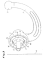
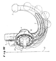
- FIGS. 2 to 9 are shown with respect to a schematically indicated vehicle rear plate 43 different phases of the targeted by the web control 28 sequence of movements during pivoting of the ball bar 3 and the ball bar bearing head 4, all of the angle data given below are only exemplary.
- FIG. 2 has the ball rod 3 in position with operating position after release for unlocking with axial displacement already lifted off the ball head 22. It is thus free to pivot in the rest position, the FIG. 3 the pivoting by 30 ° reproduces, with their reaching the guided in the Nutbahnen 31 a and 31 b of the radial groove 30 and 29 scenes pins 34 of the bolted to the ball bearing head 4 retaining ring 32 due to the web control 28, the tumbling motion of the ball rod 3 initiates.
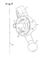
- FIG. 4 the ball rod 3 is pivoted by 60 ° and staggered by about 1.5 ° to the ball head 22 until they according to FIG. 5 at a 90 ° swivel angle and a tumbling angle of about 5 ° has reached the zenith and with the further pivoting of the ball bar 3, the wobble return movement takes place, wherein FIG. 6 at the pivoting of 120 ° shows a wobble angle of about 1.5 °, as comparable with FIG. 4 , With the in FIG. 7 shown pivoting distance of 150 ° - always based on the starting position - the web-controlled wobbling motion is completed, so that after a further pivoting of 30 ° and thus a total of 180 °, as in FIG. 8 shown, the position for locking or locking the ball rod 3 is present in the rest position of the trailer coupling.
- the distance occupied by the ball rod 3 with its cranked area in the critical section to the vehicle rear plate 43 remains approximately the same due to the tumbling motion.
- the web-controlled pivoting system with movements around a space-changing, possibly axially displaceable point can be made very narrow construction and thus takes up little space to complete.
Landscapes
- Engineering & Computer Science (AREA)
- Transportation (AREA)
- Mechanical Engineering (AREA)
- Pivots And Pivotal Connections (AREA)
- Vehicle Body Suspensions (AREA)
- Gear-Shifting Mechanisms (AREA)
- Insulation, Fastening Of Motor, Generator Windings (AREA)
- Motor Or Generator Frames (AREA)
- Glass Compositions (AREA)
- Vehicle Waterproofing, Decoration, And Sanitation Devices (AREA)
- Medicines Containing Antibodies Or Antigens For Use As Internal Diagnostic Agents (AREA)
Claims (11)
- Attelage (1) pour véhicules à moteur, comprenant un crochet (3) monté fixe sur le véhicule, pouvant pivoter et se déplacer axialement au moyen d'un guidage de mouvement (28 ; 128), portant à son extrémité libre une boule d'attelage (2) et pouvant être immobilisé en rotation aussi bien dans sa position de repos que dans sa position de travail au moyen de contours à engagement mécanique pouvant être mis en prise et faisant partie d'une tête de palier de crochet d'attelage (4 ; 104) d'une part et d'un composant faisant face à celle-ci d'autre part, caractérisé en ce que la tête de palier de crochet d'attelage (4 ; 104) est disposée sur un palier à rotule (23 ; 123), muni d'un guidage de mouvement (28; 128) pour la tête de palier de crochet d'attelage (4 ; 104), créant, lors du pivotement du crochet d'attelage (3) d'une position extrême à l'autre, des déplacements autour d'un point se modifiant dans l'espace, et en ce que le palier à rotule (23 ; 123) est disposé sur un axe creux (8 ; 108) conçu avec un verrouillage central intégré, à action axiale, de la tête de palier de crochet d'attelage (4 ; 104), afin de mettre en prise les contours à engagement mécanique (19 ; 20, 21) aussi bien en position de travail qu'en position de repos du crochet d'attelage (3).
- Attelage selon la revendication 1, caractérisé en ce que le palier à rotule (23) est pourvu d'une rotule (22) disposée dans un boîtier en forme de demi-coquille de la tête de palier de crochet d'attelage (4) au moyen d'une cage de rotule (27).
- Attelage selon la revendication 1, caractérisé en ce que le palier à rotule (123) est pourvu d'une cage de rotule (25) de forme sphérique portant la tête de palier de crochet d'attelage (104), de préférence au moyen d'une bague intermédiaire (26) de forme sphérique complémentaire.
- Attelage selon la revendication 3, caractérisé en ce que la tête de palier de crochet d'attelage (104) a une forme sphérique et est disposée dans une pièce rapportée (24) bombée.
- Attelage selon la revendication 3 ou 4, caractérisé en ce que l'axe creux (108) est disposé dans la pièce rapportée (24).
- Attelage selon la revendication 2, caractérisé en ce que l'axe creux (8) se prolonge jusque dans la rotule (22) et est réalisé d'un seul tenant avec celle-ci.
- Attelage selon l'une des revendications 1 à 6,
caractérisé en ce que le verrouillage comprend un doigt de blocage (18) guidé dans l'axe creux (8 ; 108) et pouvant être rappelé, contre l'effort exercé par un organe de poussée (41), par le biais d'un moyen de poussée ou de traction (16) actionnable de l'extérieur, et des moyens de mise en prise (39) collaborant avec le doigt de blocage (18), disposés dans des perçages radiaux (37 ; 38) de l'axe creux (8 ; 108) et pouvant être mis en prise et libérés. - Attelage selon l'une des revendications 1 à 7,
caractérisé en ce que le guidage de mouvement (28 ; 138) est réalisée sous la forme d'une coulisse (29 ; 129) dans laquelle sont engagés des éléments guidés (33, 133). - Attelage selon la revendication 8, caractérisé en ce que la coulisse (29) est réalisé sous la forme d'une gorge radiale (30) ménagée dans la rotule (22), avec un trajet des gorges (31a ; 31b) opposé sur une demi-rotule par rapport à l'autre demi-rotule et en ce que les éléments guidés (33) sont des doigts (34) disposés de manière diamétralement opposée l'un par rapport à l'autre dans une bague support (32) prévue dans la tête de palier de crochet d'attelage (4).
- Attelage selon la revendication 8 ou 9, caractérisé en ce que des évidements axiaux (35) ménagés dans la rotule (22) aux positions de pivotement extrêmes de la tête de palier de crochet d'attelage (4), dans lesquelles débouchent les gorges (31a ; 31b), sont associés aux éléments guidés (33 ; 34).
- Attelage selon la revendication 10, caractérisé en ce que le passage des gorges (31a ; 31b) aux évidements (35) a une forme d'entonnoir.
Priority Applications (1)
| Application Number | Priority Date | Filing Date | Title |
|---|---|---|---|
| EP09160049A EP2088008B8 (fr) | 2003-11-21 | 2004-10-05 | Attelage pour vehicules |
Applications Claiming Priority (2)
| Application Number | Priority Date | Filing Date | Title |
|---|---|---|---|
| DE10354753.3A DE10354753B4 (de) | 2003-11-21 | 2003-11-21 | Anhängekupplung für Kraftfahrzeuge |
| DE10354753 | 2003-11-21 |
Related Child Applications (1)
| Application Number | Title | Priority Date | Filing Date |
|---|---|---|---|
| EP09160049A Division EP2088008B8 (fr) | 2003-11-21 | 2004-10-05 | Attelage pour vehicules |
Publications (2)
| Publication Number | Publication Date |
|---|---|
| EP1533149A1 EP1533149A1 (fr) | 2005-05-25 |
| EP1533149B1 true EP1533149B1 (fr) | 2010-01-20 |
Family
ID=34428872
Family Applications (2)
| Application Number | Title | Priority Date | Filing Date |
|---|---|---|---|
| EP04023640A Expired - Lifetime EP1533149B1 (fr) | 2003-11-21 | 2004-10-05 | Attelage pour vehicules |
| EP09160049A Expired - Lifetime EP2088008B8 (fr) | 2003-11-21 | 2004-10-05 | Attelage pour vehicules |
Family Applications After (1)
| Application Number | Title | Priority Date | Filing Date |
|---|---|---|---|
| EP09160049A Expired - Lifetime EP2088008B8 (fr) | 2003-11-21 | 2004-10-05 | Attelage pour vehicules |
Country Status (3)
| Country | Link |
|---|---|
| EP (2) | EP1533149B1 (fr) |
| AT (2) | ATE465898T1 (fr) |
| DE (3) | DE10354753B4 (fr) |
Cited By (6)
| Publication number | Priority date | Publication date | Assignee | Title |
|---|---|---|---|---|
| EP2412550A1 (fr) | 2010-07-31 | 2012-02-01 | WESTFALIA - Automotive GmbH | Attelage |
| DE102010032991A1 (de) | 2010-07-31 | 2012-02-02 | Westfalia-Automotive Gmbh | Anhängekupplung |
| EP2692554A1 (fr) | 2012-08-03 | 2014-02-05 | WESTFALIA - Automotive GmbH | Attelage doté d'un dispositif de verrouillage |
| DE102013012303A1 (de) | 2012-08-03 | 2014-02-06 | Westfalia-Automotive Gmbh | Anhängekupplung mit einer Verriegelungseinrichtung |
| DE102014221742A1 (de) * | 2014-10-27 | 2016-04-28 | Zf Friedrichshafen Ag | Schwenkmodul einer Anhängerkupplung |
| EP1557300B2 (fr) † | 2004-01-22 | 2021-11-10 | ACPS Automotive GmbH | Attache remorque |
Families Citing this family (28)
| Publication number | Priority date | Publication date | Assignee | Title |
|---|---|---|---|---|
| DE102004004501B4 (de) † | 2004-01-22 | 2021-07-01 | ACPS Automotive GmbH | Anhängekupplung |
| EP1634730A1 (fr) * | 2004-09-14 | 2006-03-15 | MVG Metallverarbeitungsgesellschaft mbH | Attelage de remorque avec articulation à rotule |
| DE102005032474A1 (de) * | 2005-07-07 | 2007-01-11 | Oris Fahrzeugteile Hans Riehle Gmbh | Anhängevorrichtung |
| DE102005036185B4 (de) * | 2005-08-02 | 2018-12-13 | Volkswagen Ag | Betätigungsvorrichtung |
| DE102005047379A1 (de) * | 2005-09-28 | 2007-04-12 | Scambia Industrial Developments Aktiengesellschaft | Anhängekupplung |
| DE102006035261A1 (de) * | 2006-07-29 | 2008-01-31 | Scambia Industrial Developments Aktiengesellschaft | Anhängekupplung |
| DE102006051096B4 (de) | 2006-10-25 | 2013-09-12 | Mvg Metallverarbeitungsgesellschaft Mbh | Anhängevorrichtung |
| WO2008089145A2 (fr) | 2007-01-15 | 2008-07-24 | Phd, Inc. | Ensemble de pince à bras conducteur |
| DE102007029051A1 (de) | 2007-06-21 | 2009-01-02 | Westfalia-Automotive Gmbh | Anhängekupplung für Kraftfahrzeuge |
| DE102008018738B4 (de) * | 2008-04-14 | 2020-12-17 | THK RHYTHM AUTOMOTIVE GmbH | Fahrzeugseitige Kupplungsbaugruppe einer Anhängerkupplung |
| DE102008018739A1 (de) * | 2008-04-14 | 2009-10-15 | Trw Automotive Gmbh | Fahrzeugseitige Kupplungsbaugruppe einer Anhängerkupplung |
| DE102008047547B4 (de) | 2008-09-16 | 2014-04-03 | Westfalia-Automotive Gmbh | Anhängekupplung für Kraftfahrzeuge |
| DE102008043318A1 (de) | 2008-10-30 | 2010-05-12 | Mvg Metallverarbeitungsgesellschaft Mbh | Anhängekupplung |
| DE102009045275B4 (de) * | 2009-10-02 | 2014-01-09 | Zf Friedrichshafen Ag | Schwenkmodul für eine Anhängerkupplung |
| DE102009046931A1 (de) * | 2009-11-20 | 2011-05-26 | Zf Friedrichshafen Ag | Kugelschwenkmodul |
| DE102011078007A1 (de) * | 2011-06-22 | 2012-12-27 | Zf Friedrichshafen Ag | Anhängevorrichtung |
| DE102012008124A1 (de) † | 2012-04-25 | 2013-10-31 | Westfalia-Automotive Gmbh | Kupplungsanordnung für einen Heckträger |
| DE102013100780A1 (de) * | 2013-01-25 | 2014-07-31 | Scambia Holdings Cyprus Limited | Anhängekupplung und Lastenträgereinrichtung für eine Anhängekupplung |
| DE102013007115A1 (de) | 2013-04-21 | 2014-10-23 | Westfalia-Automotive Gmbh | Anhängekupplung |
| DE102013007123A1 (de) | 2013-04-21 | 2014-10-23 | Westfalia-Automotive Gmbh | Anhängekupplung |
| DE102014005881A1 (de) | 2013-04-21 | 2014-10-23 | Westfalia-Automotive Gmbh & Co. Kg | Anhängekupplung |
| DE102013007114A1 (de) | 2013-04-21 | 2014-10-23 | Westfalia-Automotive Gmbh | Anhängekupplung |
| DE102013007122A1 (de) | 2013-04-21 | 2014-10-23 | Westfalia-Automotive Gmbh | Anhängekupplung |
| DE102013007117A1 (de) | 2013-04-21 | 2014-10-23 | Westfalia-Automotive Gmbh | Anhängekupplung |
| DE102013007111A1 (de) | 2013-04-21 | 2014-10-23 | Westfalia-Automotive Gmbh | Anhängekupplung |
| EP2796303B1 (fr) | 2013-04-21 | 2018-05-02 | WESTFALIA - Automotive GmbH | Attelage |
| US11577561B2 (en) | 2017-12-20 | 2023-02-14 | Horizon Global (South Africa) (Pty) Ltd | Towbar with a hitch ball system |
| CN109094307B (zh) * | 2018-07-25 | 2020-06-26 | 北京汽车股份有限公司 | 拖车钩及汽车 |
Family Cites Families (13)
| Publication number | Priority date | Publication date | Assignee | Title |
|---|---|---|---|---|
| US2910310A (en) * | 1957-12-06 | 1959-10-27 | Rudolph A Mulac | Ball and socket swivel for an electric light receptacle |
| US4225260A (en) * | 1979-03-02 | 1980-09-30 | Gulf & Western Manufacturing Company | Tie rod ball joint construction |
| DE9408478U1 (de) * | 1994-05-21 | 1994-09-08 | Westfalia-Werke Knöbel GmbH & Co., 33378 Rheda-Wiedenbrück | Drehverriegelung für einen Handradantrieb von geradlinig geführten Hubzahnstangen |
| DE19654867C2 (de) * | 1995-09-13 | 1998-01-22 | Cartron Fahrzeugteile Gmbh | Schwenkbare Anhängerkupplung für Kraftfahrzeuge |
| DE19612959A1 (de) * | 1996-04-01 | 1997-10-02 | Oris Fahrzeugteile Riehle H | Anhängekupplung |
| DE19711535C2 (de) * | 1997-03-20 | 2003-07-17 | Jaeger Cartronix Gmbh | Motorisch verstellbare Anhängerkupplung für Kraftfahrzeuge |
| DE19848487A1 (de) * | 1998-10-21 | 2000-05-04 | Oris Fahrzeugteile Riehle H | Anhängekupplung |
| DE19859961C2 (de) * | 1998-12-29 | 2003-07-03 | Westfalia Automotive Gmbh & Co | Anhängerkupplung mit einem schwenkbaren Kugelhals |
| DE19944264A1 (de) | 1999-09-15 | 2001-03-22 | Jaeger Cartronix Gmbh | Anhängerkupplung mit axialem Verfahrweg |
| DE10045296A1 (de) * | 1999-10-04 | 2001-04-05 | Eberhardt Peka Fahrzeug | Anhängerkupplung für Kraftfahrzeuge |
| DE10032002A1 (de) * | 2000-06-30 | 2002-01-24 | Oris Fahrzeugteile Riehle H | Anhängevorrichtung |
| DE10160990B4 (de) * | 2001-12-10 | 2007-11-08 | Hqm Sachsenring Gmbh | Gelenk mit Gelenklagerhülse |
| ATE315490T1 (de) * | 2002-02-28 | 2006-02-15 | Kober Ag | Schwenkbare anhängevorrichtung für zugfahrzeuge |
-
2003
- 2003-11-21 DE DE10354753.3A patent/DE10354753B4/de not_active Expired - Lifetime
-
2004
- 2004-10-05 DE DE502004010669T patent/DE502004010669D1/de not_active Expired - Lifetime
- 2004-10-05 EP EP04023640A patent/EP1533149B1/fr not_active Expired - Lifetime
- 2004-10-05 AT AT09160049T patent/ATE465898T1/de not_active IP Right Cessation
- 2004-10-05 EP EP09160049A patent/EP2088008B8/fr not_active Expired - Lifetime
- 2004-10-05 AT AT04023640T patent/ATE455662T1/de not_active IP Right Cessation
- 2004-10-05 DE DE502004011113T patent/DE502004011113D1/de not_active Expired - Lifetime
Cited By (6)
| Publication number | Priority date | Publication date | Assignee | Title |
|---|---|---|---|---|
| EP1557300B2 (fr) † | 2004-01-22 | 2021-11-10 | ACPS Automotive GmbH | Attache remorque |
| EP2412550A1 (fr) | 2010-07-31 | 2012-02-01 | WESTFALIA - Automotive GmbH | Attelage |
| DE102010032991A1 (de) | 2010-07-31 | 2012-02-02 | Westfalia-Automotive Gmbh | Anhängekupplung |
| EP2692554A1 (fr) | 2012-08-03 | 2014-02-05 | WESTFALIA - Automotive GmbH | Attelage doté d'un dispositif de verrouillage |
| DE102013012303A1 (de) | 2012-08-03 | 2014-02-06 | Westfalia-Automotive Gmbh | Anhängekupplung mit einer Verriegelungseinrichtung |
| DE102014221742A1 (de) * | 2014-10-27 | 2016-04-28 | Zf Friedrichshafen Ag | Schwenkmodul einer Anhängerkupplung |
Also Published As
| Publication number | Publication date |
|---|---|
| EP2088008B1 (fr) | 2010-04-28 |
| DE502004010669D1 (de) | 2010-03-11 |
| DE10354753A1 (de) | 2005-06-30 |
| EP2088008B8 (fr) | 2010-06-16 |
| EP2088008A1 (fr) | 2009-08-12 |
| ATE465898T1 (de) | 2010-05-15 |
| EP1533149A1 (fr) | 2005-05-25 |
| DE502004011113D1 (de) | 2010-06-10 |
| ATE455662T1 (de) | 2010-02-15 |
| DE10354753B4 (de) | 2014-07-24 |
Similar Documents
| Publication | Publication Date | Title |
|---|---|---|
| EP1533149B1 (fr) | Attelage pour vehicules | |
| EP1504928B1 (fr) | Attache remorque | |
| EP0850147B1 (fr) | Dispositif d'attelage de remorque pour vehicules automobiles | |
| DE3827564C2 (de) | Schließeinrichtung für Fahrzeuge | |
| EP2017097B1 (fr) | Attelage pour véhicules automobiles | |
| EP1475253A1 (fr) | Attelage de remorque pour véhicules automobiles | |
| DE10252722B3 (de) | Anhängekupplung für Kraftfahrzeuge | |
| DE19826618C2 (de) | Anhängekupplung | |
| EP1637364B1 (fr) | Attelage de remorque | |
| EP2711207A2 (fr) | Module de basculement de sphère | |
| DE102009056397A1 (de) | Beschlagsystem für einen Fahrzeugsitz | |
| EP2711210A2 (fr) | Module de basculement de sphère | |
| EP1407901B1 (fr) | Attelage pour véhicules de traction | |
| DE202006011346U1 (de) | Schwenkbare Anhängevorrichtung für Zugfahrzeuge | |
| EP1561610B1 (fr) | Mecanisme d'attelage | |
| EP2181868B1 (fr) | Attelage | |
| WO2008049569A1 (fr) | Dispositif d'attelage | |
| DE102012025459A1 (de) | Anhängevorrichtung | |
| DE10347816B4 (de) | Anhängekupplung mit lastfreier Drehlagereinrichtung | |
| EP1614556B1 (fr) | Attelage de remorque pour véhicules automobiles | |
| EP2671739A2 (fr) | Système d'actionnement pour un attelage de véhicule automobile | |
| EP1634730A1 (fr) | Attelage de remorque avec articulation à rotule | |
| DE10340347B4 (de) | Anhängerkupplung für Kraftfahrzeuge | |
| DE20215508U1 (de) | Anhängevorrichtung für Zugfahrzeuge | |
| DE102014212598B4 (de) | Verstellbarer Fahrzeugsitz |
Legal Events
| Date | Code | Title | Description |
|---|---|---|---|
| PUAI | Public reference made under article 153(3) epc to a published international application that has entered the european phase |
Free format text: ORIGINAL CODE: 0009012 |
|
| AK | Designated contracting states |
Kind code of ref document: A1 Designated state(s): AT BE BG CH CY CZ DE DK EE ES FI FR GB GR HU IE IT LI LU MC NL PL PT RO SE SI SK TR |
|
| AX | Request for extension of the european patent |
Extension state: AL HR LT LV MK |
|
| 17P | Request for examination filed |
Effective date: 20051025 |
|
| AKX | Designation fees paid |
Designated state(s): AT BE BG CH CY CZ DE DK EE ES FI FR GB GR HU IE IT LI LU MC NL PL PT RO SE SI SK TR |
|
| 17Q | First examination report despatched |
Effective date: 20060717 |
|
| RAP1 | Party data changed (applicant data changed or rights of an application transferred) |
Owner name: WESTFALIA - AUTOMOTIVE GMBH |
|
| GRAP | Despatch of communication of intention to grant a patent |
Free format text: ORIGINAL CODE: EPIDOSNIGR1 |
|
| RTI1 | Title (correction) |
Free format text: TRAILER HITCH FOR VEHICLES |
|
| GRAS | Grant fee paid |
Free format text: ORIGINAL CODE: EPIDOSNIGR3 |
|
| GRAA | (expected) grant |
Free format text: ORIGINAL CODE: 0009210 |
|
| AK | Designated contracting states |
Kind code of ref document: B1 Designated state(s): AT BE BG CH CY CZ DE DK EE ES FI FR GB GR HU IE IT LI LU MC NL PL PT RO SE SI SK TR |
|
| REG | Reference to a national code |
Ref country code: GB Ref legal event code: FG4D Free format text: NOT ENGLISH |
|
| REG | Reference to a national code |
Ref country code: CH Ref legal event code: EP |
|
| REG | Reference to a national code |
Ref country code: IE Ref legal event code: FG4D |
|
| REF | Corresponds to: |
Ref document number: 502004010669 Country of ref document: DE Date of ref document: 20100311 Kind code of ref document: P |
|
| REG | Reference to a national code |
Ref country code: NL Ref legal event code: VDEP Effective date: 20100120 |
|
| PG25 | Lapsed in a contracting state [announced via postgrant information from national office to epo] |
Ref country code: ES Free format text: LAPSE BECAUSE OF FAILURE TO SUBMIT A TRANSLATION OF THE DESCRIPTION OR TO PAY THE FEE WITHIN THE PRESCRIBED TIME-LIMIT Effective date: 20100501 Ref country code: NL Free format text: LAPSE BECAUSE OF FAILURE TO SUBMIT A TRANSLATION OF THE DESCRIPTION OR TO PAY THE FEE WITHIN THE PRESCRIBED TIME-LIMIT Effective date: 20100120 Ref country code: PT Free format text: LAPSE BECAUSE OF FAILURE TO SUBMIT A TRANSLATION OF THE DESCRIPTION OR TO PAY THE FEE WITHIN THE PRESCRIBED TIME-LIMIT Effective date: 20100520 |
|
| REG | Reference to a national code |
Ref country code: IE Ref legal event code: FD4D |
|
| PG25 | Lapsed in a contracting state [announced via postgrant information from national office to epo] |
Ref country code: SI Free format text: LAPSE BECAUSE OF FAILURE TO SUBMIT A TRANSLATION OF THE DESCRIPTION OR TO PAY THE FEE WITHIN THE PRESCRIBED TIME-LIMIT Effective date: 20100120 Ref country code: FI Free format text: LAPSE BECAUSE OF FAILURE TO SUBMIT A TRANSLATION OF THE DESCRIPTION OR TO PAY THE FEE WITHIN THE PRESCRIBED TIME-LIMIT Effective date: 20100120 Ref country code: PL Free format text: LAPSE BECAUSE OF FAILURE TO SUBMIT A TRANSLATION OF THE DESCRIPTION OR TO PAY THE FEE WITHIN THE PRESCRIBED TIME-LIMIT Effective date: 20100120 |
|
| PG25 | Lapsed in a contracting state [announced via postgrant information from national office to epo] |
Ref country code: CY Free format text: LAPSE BECAUSE OF FAILURE TO SUBMIT A TRANSLATION OF THE DESCRIPTION OR TO PAY THE FEE WITHIN THE PRESCRIBED TIME-LIMIT Effective date: 20100120 Ref country code: SE Free format text: LAPSE BECAUSE OF FAILURE TO SUBMIT A TRANSLATION OF THE DESCRIPTION OR TO PAY THE FEE WITHIN THE PRESCRIBED TIME-LIMIT Effective date: 20100120 Ref country code: RO Free format text: LAPSE BECAUSE OF FAILURE TO SUBMIT A TRANSLATION OF THE DESCRIPTION OR TO PAY THE FEE WITHIN THE PRESCRIBED TIME-LIMIT Effective date: 20100120 Ref country code: IE Free format text: LAPSE BECAUSE OF FAILURE TO SUBMIT A TRANSLATION OF THE DESCRIPTION OR TO PAY THE FEE WITHIN THE PRESCRIBED TIME-LIMIT Effective date: 20100120 Ref country code: GR Free format text: LAPSE BECAUSE OF FAILURE TO SUBMIT A TRANSLATION OF THE DESCRIPTION OR TO PAY THE FEE WITHIN THE PRESCRIBED TIME-LIMIT Effective date: 20100421 Ref country code: EE Free format text: LAPSE BECAUSE OF FAILURE TO SUBMIT A TRANSLATION OF THE DESCRIPTION OR TO PAY THE FEE WITHIN THE PRESCRIBED TIME-LIMIT Effective date: 20100120 |
|
| PLBE | No opposition filed within time limit |
Free format text: ORIGINAL CODE: 0009261 |
|
| STAA | Information on the status of an ep patent application or granted ep patent |
Free format text: STATUS: NO OPPOSITION FILED WITHIN TIME LIMIT |
|
| PG25 | Lapsed in a contracting state [announced via postgrant information from national office to epo] |
Ref country code: SK Free format text: LAPSE BECAUSE OF FAILURE TO SUBMIT A TRANSLATION OF THE DESCRIPTION OR TO PAY THE FEE WITHIN THE PRESCRIBED TIME-LIMIT Effective date: 20100120 Ref country code: CZ Free format text: LAPSE BECAUSE OF FAILURE TO SUBMIT A TRANSLATION OF THE DESCRIPTION OR TO PAY THE FEE WITHIN THE PRESCRIBED TIME-LIMIT Effective date: 20100120 Ref country code: BG Free format text: LAPSE BECAUSE OF FAILURE TO SUBMIT A TRANSLATION OF THE DESCRIPTION OR TO PAY THE FEE WITHIN THE PRESCRIBED TIME-LIMIT Effective date: 20100420 |
|
| 26N | No opposition filed |
Effective date: 20101021 |
|
| PG25 | Lapsed in a contracting state [announced via postgrant information from national office to epo] |
Ref country code: DK Free format text: LAPSE BECAUSE OF FAILURE TO SUBMIT A TRANSLATION OF THE DESCRIPTION OR TO PAY THE FEE WITHIN THE PRESCRIBED TIME-LIMIT Effective date: 20100120 |
|
| PG25 | Lapsed in a contracting state [announced via postgrant information from national office to epo] |
Ref country code: IT Free format text: LAPSE BECAUSE OF FAILURE TO SUBMIT A TRANSLATION OF THE DESCRIPTION OR TO PAY THE FEE WITHIN THE PRESCRIBED TIME-LIMIT Effective date: 20100120 |
|
| BERE | Be: lapsed |
Owner name: WESTFALIA - AUTOMOTIVE G.M.B.H. Effective date: 20101031 |
|
| PG25 | Lapsed in a contracting state [announced via postgrant information from national office to epo] |
Ref country code: MC Free format text: LAPSE BECAUSE OF NON-PAYMENT OF DUE FEES Effective date: 20101031 |
|
| REG | Reference to a national code |
Ref country code: CH Ref legal event code: PL |
|
| GBPC | Gb: european patent ceased through non-payment of renewal fee |
Effective date: 20101005 |
|
| PG25 | Lapsed in a contracting state [announced via postgrant information from national office to epo] |
Ref country code: LI Free format text: LAPSE BECAUSE OF NON-PAYMENT OF DUE FEES Effective date: 20101031 Ref country code: CH Free format text: LAPSE BECAUSE OF NON-PAYMENT OF DUE FEES Effective date: 20101031 |
|
| PG25 | Lapsed in a contracting state [announced via postgrant information from national office to epo] |
Ref country code: BE Free format text: LAPSE BECAUSE OF NON-PAYMENT OF DUE FEES Effective date: 20101031 Ref country code: GB Free format text: LAPSE BECAUSE OF NON-PAYMENT OF DUE FEES Effective date: 20101005 |
|
| REG | Reference to a national code |
Ref country code: AT Ref legal event code: MM01 Ref document number: 455662 Country of ref document: AT Kind code of ref document: T Effective date: 20101005 |
|
| PG25 | Lapsed in a contracting state [announced via postgrant information from national office to epo] |
Ref country code: AT Free format text: LAPSE BECAUSE OF NON-PAYMENT OF DUE FEES Effective date: 20101005 |
|
| PG25 | Lapsed in a contracting state [announced via postgrant information from national office to epo] |
Ref country code: HU Free format text: LAPSE BECAUSE OF FAILURE TO SUBMIT A TRANSLATION OF THE DESCRIPTION OR TO PAY THE FEE WITHIN THE PRESCRIBED TIME-LIMIT Effective date: 20100721 Ref country code: LU Free format text: LAPSE BECAUSE OF NON-PAYMENT OF DUE FEES Effective date: 20101005 |
|
| PG25 | Lapsed in a contracting state [announced via postgrant information from national office to epo] |
Ref country code: TR Free format text: LAPSE BECAUSE OF FAILURE TO SUBMIT A TRANSLATION OF THE DESCRIPTION OR TO PAY THE FEE WITHIN THE PRESCRIBED TIME-LIMIT Effective date: 20100120 |
|
| REG | Reference to a national code |
Ref country code: FR Ref legal event code: PLFP Year of fee payment: 12 |
|
| REG | Reference to a national code |
Ref country code: FR Ref legal event code: PLFP Year of fee payment: 13 |
|
| REG | Reference to a national code |
Ref country code: FR Ref legal event code: PLFP Year of fee payment: 14 |
|
| REG | Reference to a national code |
Ref country code: FR Ref legal event code: PLFP Year of fee payment: 15 |
|
| PGFP | Annual fee paid to national office [announced via postgrant information from national office to epo] |
Ref country code: FR Payment date: 20221020 Year of fee payment: 19 |
|
| PGFP | Annual fee paid to national office [announced via postgrant information from national office to epo] |
Ref country code: DE Payment date: 20230912 Year of fee payment: 20 |
|
| PG25 | Lapsed in a contracting state [announced via postgrant information from national office to epo] |
Ref country code: FR Free format text: LAPSE BECAUSE OF NON-PAYMENT OF DUE FEES Effective date: 20231031 |
|
| REG | Reference to a national code |
Ref country code: DE Ref legal event code: R071 Ref document number: 502004010669 Country of ref document: DE |