EP2711207A2 - Module de basculement de sphère - Google Patents
Module de basculement de sphère Download PDFInfo
- Publication number
- EP2711207A2 EP2711207A2 EP13180798.4A EP13180798A EP2711207A2 EP 2711207 A2 EP2711207 A2 EP 2711207A2 EP 13180798 A EP13180798 A EP 13180798A EP 2711207 A2 EP2711207 A2 EP 2711207A2
- Authority
- EP
- European Patent Office
- Prior art keywords
- ball
- locking
- spindle
- module
- pin
- Prior art date
- Legal status (The legal status is an assumption and is not a legal conclusion. Google has not performed a legal analysis and makes no representation as to the accuracy of the status listed.)
- Withdrawn
Links
Images


Classifications
-
- B—PERFORMING OPERATIONS; TRANSPORTING
- B60—VEHICLES IN GENERAL
- B60D—VEHICLE CONNECTIONS
- B60D1/00—Traction couplings; Hitches; Draw-gear; Towing devices
- B60D1/48—Traction couplings; Hitches; Draw-gear; Towing devices characterised by the mounting
- B60D1/54—Traction couplings; Hitches; Draw-gear; Towing devices characterised by the mounting collapsible or retractable when not in use, e.g. hide-away hitches
-
- F—MECHANICAL ENGINEERING; LIGHTING; HEATING; WEAPONS; BLASTING
- F16—ENGINEERING ELEMENTS AND UNITS; GENERAL MEASURES FOR PRODUCING AND MAINTAINING EFFECTIVE FUNCTIONING OF MACHINES OR INSTALLATIONS; THERMAL INSULATION IN GENERAL
- F16C—SHAFTS; FLEXIBLE SHAFTS; ELEMENTS OR CRANKSHAFT MECHANISMS; ROTARY BODIES OTHER THAN GEARING ELEMENTS; BEARINGS
- F16C11/00—Pivots; Pivotal connections
- F16C11/04—Pivotal connections
- F16C11/10—Arrangements for locking
Definitions
- the invention relates to a ball pivot module for a trailer hitch according to the preamble of claim 1.
- a switching pin prevents after unlocking, which recoils the locking bolt by the force of a spring in the locked position.
- a ball pivoting module in particular for a trailer hitch, which has a ball pin, which ball pin comprises a ball joint and is mounted in a housing, wherein in the ball pin a recess is provided, in which a locking pin is arranged axially displaceable to a substantially vertical to actuate the locking pin movable means for locking and unlocking the ball pivot module, wherein a drive is provided for the motorized actuation of the locking pin, in particular an electric motor, wherein the drive is coupled via a compound of axially rigid elements with the locking pin.
- the ball pivoting module is characterized in that the drive and the said connection are adapted to move the locking pin within the recess by a motor to its locking position and thereby to actuate the means for locking the ball pivot module.
- the recess may be formed as a particular through hole, preferably bore koxial to the longitudinal axis of the ball stud.
- the means for locking may be formed of locking elements or locking units consisting of at least one ball or also a combination of balls, split rings and hollow or solid cylindrical members which move approximately transversely to the longitudinal axis of the ball stud in suitable tracks.
- the rigid connection comprises a first rigid element, which first rigid element is coupled to the drive, and a second rigid element, which second rigid element is coupled to the locking bolt.
- the first rigid element may be a gear and the second rigid element may be a spindle, wherein preferably the gear is arranged substantially concentrically around the spindle longitudinal axis of the spindle and cooperating with the spindle.
- a spindle, in particular threaded spindle is a round rod-shaped machine element which, together with other elements, converts a rotary movement into a translational movement, wherein a thread, e.g. a trapezoidal thread is formed.
- the spindle preferably extends within the recess of the ball pin and is non-positively and / or positively or materially coupled to the locking pin.
- the proposed drive (electric motor) transmits a rotational movement to the gearwheel directly or by means of a separate drive shaft or a drive pinion. If the gear wheel and the spindle are coupled to one another via a positive connection, then the interaction of gear wheel and spindle causes the translatory drive of the locking bolt.
- the spindle position can also be determined directly by sensors, wherein at least one first sensor is used.
- the invention is not limited to the use of a particular type of sensor.
- a button can be used to query the spindle position.
- Other usable sensors are based on inductive, capacitive or optical and thus non-contact principles of action. Especially for the determination of the spindle position and so-called. Linear sensors can be used to determine a wear of the assembly and possibly replace the ball pivot module.
- the gear has a first thread, in particular an internal thread
- the spindle has a second thread, in particular an external thread, which are in operative connection, in particular meshing engagement.
- the gear is driven by said drive or motor, preferably an electric motor, which eliminates the need for manual (manual) operation and greatly enhances user comfort.
- the spindle and the locking pin are non-positively and / or positively or materially preferably connected via a snap ring and associated latching structures, in particular a groove on the spindle or locking pin.
- a spindle end in a corresponding receptacle may be held in the locking pin, but without the invention would be limited to locking pin with a blind hole.
- the connection via a snap ring and the associated Verrast Modellen allows some movement of the spindle relative to the locking pin in a determined by the arrangement of snap ring and Verrast Modellen stroke within said recording and depending on their depth. This allows the spindle to assume a rest position during trailer operation, without having to absorb loads that are introduced via the locking pin.
- the ball pivot module additionally has a (central) pressure spring, as it is already known from the prior art.
- the spring may be arranged around the spindle within the recess of the ball stud.
- the drive via the spindle and the locking pin provides for the desired locking by the locking pin is moved in the recess as far as possible in its locking position, wherein it actuates the means for locking the ball pivot module.
- a second sensor which detects the position (rotational position) of a further gear, wherein the further gear is coupled to the housing of the ball pivot module, so that on the position of this gear and the position of the housing and consequently the position of a ball bar connected to the housing is detectable.
- the second sensor for detecting the pivot position may, for example, a button, an inductive sensor, a capacitive sensor, a Hall sensor, a magnetostrictive sensor or the like non-contact sensor, which detects the position of the gear.
- Said gear can for this purpose have certain structures to which the sensor responds, for example, projections or protrusions, recesses, permanent magnets used, optical markings or the like, depending on the sensor type used. Since the position of the further gear is coupled via the mechanism of the ball pivot module to the position of the housing, the first sensor thus indirectly detects the position of the housing. It should be emphasized that in this further gear is basically a different gear than that gear, which is used to drive the spindle and thus to effect the unlocking / locking.
- the other gear is used to effect a rotational-tilting movement of the ball rod, however, for example, corresponds to the pivoted-out operating position of the ball bar just the aforementioned locking position of the locking pin, so that the further gear can also be used to determine the locking position of the locking pin.
- the second sensor detects a first position of the further gear, which corresponds to an operating position of a trailer hook provided on the ball pivot module (ball bar), and a second position of the further gear, which corresponds to a rest position of the trailer hook.
- the trailer hook is rigidly connected to the housing of the ball pivot module. This results from the position of the housing, the position of the trailer hook.
- the position of the housing and thus also the position of the trailer hook or the ball rod can be indirectly detected via the position of the further gear.
- the first position and the second position which are preferably offset by approximately 180 ° to each other, which thus - without restriction - corresponds to half a rotation of the other gear, respectively a locking position, ie a rest position with swiveled ball rod and a Operating or safety position with swiveled out ball rod.
- a locking position ie a rest position with swiveled ball rod
- a Operating or safety position with swiveled out ball rod.
- the further gear which is preferably rotatably mounted on the ball pivot, can be used - as also described above. This can effectively prevent a false lock.
- the pivoting can go a bit beyond the first and / or second position, after the signal for reaching the rest or operating position has already been given by the first and / or second sensor. If then the ball pivot module to be locked, the locking unit can not retract completely. Now, when a turn is pivoted back, the locks audibly engage, which increases the reliability and improves the function control. Alternatively, the pivoting may even stop slightly before reaching the mentioned positions. Then the lock is activated, and the module is then pivoted further or at the same time. As a result, a tension of the system can be achieved.
- the first sensor can also be designed as a button, inductive sensor, capacitive sensor, Hall sensor or magnetostrictive or optical sensor and queries the position of the spindle. With a defined immersion depth in the ball stud a safe locking state can be detected. Only when this condition is reached is a complete interlock signaled, e.g. by an optical or acoustic signal.
- the housing is pivotally mounted around the ball stud, which housing in turn is connected to the ball bar.
- Housing and ball bar are with respect to a rotational movement about the longitudinal axis of the ball pin, which rotational movement is preferably effected by the said further gear, coupled.
- With respect to a tilting movement about a substantially vertical tilting axis is the movement of the Longitudinal axis decoupled.
- the ball joint of the ball stud for this purpose on a non-planar control surface which is in engagement with a provided on or in the housing control element, in particular with a positive guide pin, so that this system causes a positive guidance of the ball stud in which the ball pin is rotated during a movement between the operating position and the rest position about the axis of rotation and also the housing is tilted about the tilt axis.
- This configuration provides a space-saving solution for creating a pivot module, which can perform the aforementioned rotation-tilting movement.
- Fig. 1 is a perspective view of a trailer hitch 1 with a ball pivot module 2 according to one embodiment.
- the trailer hitch 1 is arranged on a cross pipe 4, on which also a longitudinal connection 3 is provided for attachment to a vehicle and cable 5 and plug 6 to supply a likewise arranged on the cross tube 4 drive 7 in the form of at least one electric motor with energy.
- a connector 32 for connecting the two components is arranged between the drive 7 and the swivel module 2.
- a pivotable ball rod 8 tilte. with a coupling ball 9 is provided on the swivel module 2.
- the drive 7 comprises, in addition to the already mentioned electric motor, which provides for the unlocking and locking of the ball bar or the swivel module, yet another electric motor, which is responsible for the pivotal movement of the trailer hitch 1. This will be discussed in more detail below.
- Fig. 2 shows two 90 ° rotated against each other sectional views of a ball pivot module 2 with locking and unlocking according to the prior art for the purpose of a better understanding of the invention.
- a central spring (compression spring) 43 and a locking pin 44 are arranged for locking and unlocking according to the prior art.
- the Locking bolt 44 is guided in the longitudinal direction of the recess 42 within this displaceable.
- a circular-cylindrical guide channel 45 is provided in a joint ball 10 of the ball pivot module 2, which is open towards the recess 42 and extends through the wall of the joint ball 10 in a guide direction extending transversely to the longitudinal direction.
- a device for locking and unlocking the pivot module which comprises a ball 61 and a guide pin 46 which is or in the guide direction within the bore 42 extending transversely to the bore or are.
- the ball 61 acts with a working surface 47 (see FIG. 3 ) of the locking pin 44, which is oriented obliquely to the longitudinal direction.
- the locking pin 44 is pressed to lock by means of the central spring 43 in the longitudinal direction by the spring 43 downwards in the direction of ball 10. Due to the inclined working surface 47 (see FIG. 3 ) thereby the ball 61 and corresponding to the guide pin 46 in the guide direction is pressed radially outward into a trough-shaped locking recess 12a in a housing 12 of the ball pivot module 2.
- the locking recess 12a is formed by a locking insert 12b fixed in the housing 12, in which a pressure pin 48 is provided, which presses by means of a compression spring 49 against the guide pin 46 in the direction of the longitudinal extent of the guide channel 45. Since the guide pin 46 engages both in the guide channel 45 and in the locking recess 12 a, the ball joint 10 is rigidly fixed in the housing 12. When the locking pin 44 moves up again and the ball 61 correspondingly radially inwardly from the guide pin 46, the locking pin 44 is in the release position, in which the guide pin 46 by the pressurized by the compression spring 49 pressure pin 48 from the Arretsammlungsaushyroidung 12a is disengaged. The ball joint 10 is then no longer locked by the guide pin 46 in the housing 12 and can move relative thereto.
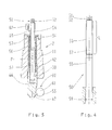
- Fig. 3 shows a section through a ball pivot module 2 for explaining an embodiment of the locking and unlocking function according to the invention.
- a spindle 50 is provided, which can move linearly in a recess 42 of the ball stud 11 up and down.
- the electric motor has an in FIG. 3 not shown shaft connected to the gear 34 so that the gear 34 performs a rotational movement about a central axis 37 corresponding to the spindle longitudinal axis 37.
- the toothed wheel 34 has a trapezoidal internal thread 57, which is not shown in detail here, and which fits into a trapezoidal external thread 56 of the spindle 50, which is likewise not shown in detail.
- the spindle 50 is connected to the locking pin 44 and locks or unlocks the locking system by pushing or pulling the locking pin 44.
- the locking pin 44 actuates a locking device 60.
- the locking device 60 acts as a substantially perpendicular to the locking pin 44 movable means for locking and unlocking and comprises a ball 61.
- a sensor 62 detects it on the basis of a lateral recess 63 of the spindle 50 whose position. Depending on the direction of rotation, the spindle 50 presses the locking pin 44 into the housing 12 or pulls it out.
- the ball 61 of the locking device 60 is analogous FIG. 2 on a working surface 47 of the locking bolt 44, which is formed as a recess in the locking bolt 44.
- the Sensor 62 detects the recess 63 of the spindle 50 or its limitations and consequently at least the switching point 54. On the position of the recess 63 relative to the sensor 62 thus the position of the spindle 50 relative to the ball pin 11 and thus the locking position can be detected.
- Fig. 4 shows a detailed view of a spindle 50, which is identical or at least similar to the spindle in Fig. 3 is constructed.
- the spindle 50 is provided at its outer periphery 55 with the already mentioned external thread 56, which extends over a length L.
- the locking device 51 is arranged on the spindle 50.
- gear 34 causes the locking device 51 that the spindle 50 performs a linear movement along the axis of rotation 37 of the gear 34 within the recess 42, as described above, depending on the direction of rotation of the gear 34th
- Fig. 5 shows a sectional view of the gear 34, which is here recognizable with the mentioned internal thread 57 is provided.
- the internal thread 57 is in positive engagement with the external thread 56 of the spindle.
- the gear 34 rotates about the axis of rotation 37 and acts as a spindle nut.
- Fig. 6 shows a detailed view of the locking bolt 44, which is provided with a cylindrical recess 58 in the manner of a blind hole, in which or which the spindle 50 is immersed.
- a latching structure 64 is formed, which cooperates with a snap ring 59.
- the spindle 50 and the locking pin 44 are relative to each other over a certain stroke range H along the axis 37 movable until the spindle end abuts the bottom of the blind hole. In this way, an optimally rigid, unyielding locking can be achieved.
- a pressure spring (not shown) can additionally be arranged within the recess 42 and around the spindle 50. Then it is possible, the spindle according to FIG. 6 after reaching optimal locking a piece far out of the locking pin 44, so that then the lock is held only or additionally by the compression spring. This results in a certain mechanical decoupling of the spindle 50 and the locking bolt 44, whereby advantageously not all forces acting on the ball rod forces also act directly on the drive train for the locking.
- Fig. 7 is a perspective view of an entire ball pivot module 2 including the components of the FIGS. 3 to 6 , As can be seen here, a tilting axis 41 of the ball pivoting module 2 is arranged offset by 90 ° relative to a driving pin 36. This makes it possible that a tilting movement about the axis 41 can be performed without the driving pin 36 tilted in a receiving device 40, also shown, since he can dip in and out of the tilting movement in this. On the elements 36 and 41 will be described below with reference to FIGS. 8A to E discussed in more detail. Furthermore, here the axis of rotation 37 can be seen, about which the ball pin 11 is rotatable. These features relating to a rotational / tilting movement of the ball pivot module or the ball rod can also be realized accordingly in the context of the present invention.
- the drive shaft 23 is formed as a two-toothed shaft and is engaged with the gear 34 '.
- the shaft 23 is part of a drive unit 33 and comprises a gear 34 ', which is formed with a partial toothing with a plurality of teeth 35. In the illustrated example, the ratio of the number of teeth is about 1:12.
- the gear 34 ' is fixedly arranged in a region without teeth of the aforementioned driving pin 36, which is specifically in Figure 8A is shown.
- the driving pin 36 is pressed into the gear 34 'and acts as a driver for the locking ring 22, which the housing 12 (see. FIG. 7 ) Closes on one side and thus rotatably connect to the housing.
- the gear 34 ' is rotatably mounted in an intermediate ring 38 which on the ball pin 11 (analog FIG. 2 ) of the ball pivot module 2 is pressed.
- a race 30 is shown, via which a seal, not shown, can be rotatably connected to the housing 12.
- the locking ring 22 is shown in more detail.
- the locking ring 22 has a receiving device 40, in which the driving pin 36 in the assembled state, which in Figure 8E is shown, is received and in which the driving pin 36 axially relative to its own longitudinal extent and radially relative to the locking ring 22 reciprocally movable when the housing 12 together with the locking ring 22 pivots about the ball pivot (axis 41, see. Fig. 7 ).
- the intermediate ring 38 is provided with a bore 39, which in FIG. 8B is shown. Through the bore 39, the output shaft 23 can be guided in the assembled state, as in Figure 8D is recognizable.
- An electric motor drives the output shaft 23 designed as a two-toothed shaft.
- the output shaft 23 drives the gear 34 ', which is rotatably mounted on the intermediate ring 38.
- the driving pin 36 is fixedly connected to the gear 34 '. By the rotation of the gear 34 'of the driving pin 36 is moved. It engages in the receiving device 40 of the closure ring 22, whereby a rotational movement of the housing 12 and thus the ball bar 8 (see FIG. 1 ) is produced.
- the closure ring 22 carries out together with the joint ball 10 of the ball pin 11 from a rotational movement. The additional tilting movement of the housing or the ball rod arises from the rotational movement through the Wirverbindg.
- Fig. 9 shows a perspective view of the gear 34 'according to the FIGS. 8A to E ,
- the gear 34 ' has a partial toothing 35.
- a circumferential semi-circular elevation 65 is arranged on an upper side of the gear 34 '.
- the ends of the elevation 65 provide landmarks for detection of the position of the gear 34 'with a sensor (not shown) as described above.
- the starting point P1 of the increase 65 corresponds to a first position, in particular, the operating position of the ball rod 8
- the end point P2 of the increase 65 corresponds to a second position, in particular the rest position of the ball rod 8.
- a corresponding sensor signal can thus be used to display these positions.
- the invention is in principle not limited to a specific sensor type.
Landscapes
- Engineering & Computer Science (AREA)
- Transportation (AREA)
- Mechanical Engineering (AREA)
- Pivots And Pivotal Connections (AREA)
Applications Claiming Priority (1)
| Application Number | Priority Date | Filing Date | Title |
|---|---|---|---|
| DE102012216798.6A DE102012216798A1 (de) | 2012-09-19 | 2012-09-19 | Kugelschwenkmodul |
Publications (2)
| Publication Number | Publication Date |
|---|---|
| EP2711207A2 true EP2711207A2 (fr) | 2014-03-26 |
| EP2711207A3 EP2711207A3 (fr) | 2014-12-10 |
Family
ID=49000830
Family Applications (1)
| Application Number | Title | Priority Date | Filing Date |
|---|---|---|---|
| EP13180798.4A Withdrawn EP2711207A3 (fr) | 2012-09-19 | 2013-08-19 | Module de basculement de sphère |
Country Status (2)
| Country | Link |
|---|---|
| EP (1) | EP2711207A3 (fr) |
| DE (1) | DE102012216798A1 (fr) |
Cited By (9)
| Publication number | Priority date | Publication date | Assignee | Title |
|---|---|---|---|---|
| CN109334363A (zh) * | 2018-11-27 | 2019-02-15 | 天津航天机电设备研究所 | 一种具有包络特性的旋转叶片式对接机构 |
| CN110588260A (zh) * | 2019-08-27 | 2019-12-20 | 江苏大学 | 一种防松拖挂式房车的连接球头及连接系统 |
| US10670479B2 (en) | 2018-02-27 | 2020-06-02 | Methode Electronics, Inc. | Towing systems and methods using magnetic field sensing |
| US10696109B2 (en) | 2017-03-22 | 2020-06-30 | Methode Electronics Malta Ltd. | Magnetolastic based sensor assembly |
| CN111927937A (zh) * | 2020-08-12 | 2020-11-13 | 内蒙古第一机械集团股份有限公司 | 一种具有擒纵伸缩功能的球笼式传动结构 |
| US11084342B2 (en) | 2018-02-27 | 2021-08-10 | Methode Electronics, Inc. | Towing systems and methods using magnetic field sensing |
| US11135882B2 (en) | 2018-02-27 | 2021-10-05 | Methode Electronics, Inc. | Towing systems and methods using magnetic field sensing |
| US11221262B2 (en) | 2018-02-27 | 2022-01-11 | Methode Electronics, Inc. | Towing systems and methods using magnetic field sensing |
| US11491832B2 (en) | 2018-02-27 | 2022-11-08 | Methode Electronics, Inc. | Towing systems and methods using magnetic field sensing |
Families Citing this family (3)
| Publication number | Priority date | Publication date | Assignee | Title |
|---|---|---|---|---|
| DE102017102504A1 (de) | 2017-02-08 | 2018-08-09 | Bosal Acps Holding 2 B.V. | Anhängekupplung |
| DE102017102505A1 (de) * | 2017-02-08 | 2018-08-09 | Bosal Acps Holding 2 B.V. | Anhängekupplung |
| CN111050503B (zh) * | 2019-12-19 | 2024-03-08 | 珠海格力电器股份有限公司 | 具有防护效果的检测结构及天井机 |
Citations (2)
| Publication number | Priority date | Publication date | Assignee | Title |
|---|---|---|---|---|
| DE102007029051A1 (de) | 2007-06-21 | 2009-01-02 | Westfalia-Automotive Gmbh | Anhängekupplung für Kraftfahrzeuge |
| DE102008002207A1 (de) | 2008-06-04 | 2009-12-10 | Zf Friedrichshafen Ag | Kugelgelenk |
Family Cites Families (11)
| Publication number | Priority date | Publication date | Assignee | Title |
|---|---|---|---|---|
| DE19711535C2 (de) * | 1997-03-20 | 2003-07-17 | Jaeger Cartronix Gmbh | Motorisch verstellbare Anhängerkupplung für Kraftfahrzeuge |
| DE19902355A1 (de) * | 1999-01-21 | 2000-08-03 | Oris Fahrzeugteile Riehle H | Anhängekupplung |
| DE10336445B4 (de) * | 2003-08-08 | 2006-04-20 | Westfalia-Automotive Gmbh & Co. Kg | Anhängerkupplung für Kraftfahrzeuge |
| DE202005006751U1 (de) * | 2005-04-26 | 2005-07-07 | Jaeger Cartronix Gmbh | Antrieb für eine Anhängerkupplung |
| DE102006058734B4 (de) * | 2006-12-13 | 2016-01-21 | Westfalia-Automotive Gmbh | Vorrichtung zum motorischen Entriegeln horizontal abnehmbarer Anhängerkupplungen |
| DE102008034851A1 (de) * | 2008-06-06 | 2009-12-17 | Westfalia-Automotive Gmbh | Anhängekupplung |
| DE102009045275B4 (de) * | 2009-10-02 | 2014-01-09 | Zf Friedrichshafen Ag | Schwenkmodul für eine Anhängerkupplung |
| DE102009045276A1 (de) * | 2009-10-02 | 2011-04-28 | Zf Friedrichshafen Ag | Kugelgelenk |
| DE202009014826U1 (de) * | 2009-11-03 | 2011-03-17 | Westfalia-Automotive Gmbh | Verbindungseinrichtung für eine Anhängekupplung oder einen Lastenträger |
| DE102010032991A1 (de) * | 2010-07-31 | 2012-02-02 | Westfalia-Automotive Gmbh | Anhängekupplung |
| DE202011103345U1 (de) * | 2011-03-23 | 2012-06-25 | Westfalia-Automotive Gmbh | Steuergerät für eine Anhängekupplung und Anhängekupplung mit einem Steuergerät |
-
2012
- 2012-09-19 DE DE102012216798.6A patent/DE102012216798A1/de not_active Withdrawn
-
2013
- 2013-08-19 EP EP13180798.4A patent/EP2711207A3/fr not_active Withdrawn
Patent Citations (2)
| Publication number | Priority date | Publication date | Assignee | Title |
|---|---|---|---|---|
| DE102007029051A1 (de) | 2007-06-21 | 2009-01-02 | Westfalia-Automotive Gmbh | Anhängekupplung für Kraftfahrzeuge |
| DE102008002207A1 (de) | 2008-06-04 | 2009-12-10 | Zf Friedrichshafen Ag | Kugelgelenk |
Cited By (13)
| Publication number | Priority date | Publication date | Assignee | Title |
|---|---|---|---|---|
| US10696109B2 (en) | 2017-03-22 | 2020-06-30 | Methode Electronics Malta Ltd. | Magnetolastic based sensor assembly |
| US10940726B2 (en) | 2017-03-22 | 2021-03-09 | Methode Electronics Malta Ltd. | Magnetoelastic based sensor assembly |
| US11084342B2 (en) | 2018-02-27 | 2021-08-10 | Methode Electronics, Inc. | Towing systems and methods using magnetic field sensing |
| US10670479B2 (en) | 2018-02-27 | 2020-06-02 | Methode Electronics, Inc. | Towing systems and methods using magnetic field sensing |
| US11135882B2 (en) | 2018-02-27 | 2021-10-05 | Methode Electronics, Inc. | Towing systems and methods using magnetic field sensing |
| US11221262B2 (en) | 2018-02-27 | 2022-01-11 | Methode Electronics, Inc. | Towing systems and methods using magnetic field sensing |
| US11491832B2 (en) | 2018-02-27 | 2022-11-08 | Methode Electronics, Inc. | Towing systems and methods using magnetic field sensing |
| CN109334363A (zh) * | 2018-11-27 | 2019-02-15 | 天津航天机电设备研究所 | 一种具有包络特性的旋转叶片式对接机构 |
| CN109334363B (zh) * | 2018-11-27 | 2023-12-19 | 天津航天机电设备研究所 | 一种具有包络特性的旋转叶片式对接机构 |
| CN110588260A (zh) * | 2019-08-27 | 2019-12-20 | 江苏大学 | 一种防松拖挂式房车的连接球头及连接系统 |
| CN110588260B (zh) * | 2019-08-27 | 2022-11-18 | 江苏大学 | 一种防松拖挂式房车的连接球头及连接系统 |
| CN111927937A (zh) * | 2020-08-12 | 2020-11-13 | 内蒙古第一机械集团股份有限公司 | 一种具有擒纵伸缩功能的球笼式传动结构 |
| CN111927937B (zh) * | 2020-08-12 | 2023-02-17 | 内蒙古第一机械集团股份有限公司 | 一种具有擒纵伸缩功能的球笼式传动结构 |
Also Published As
| Publication number | Publication date |
|---|---|
| DE102012216798A1 (de) | 2014-03-20 |
| EP2711207A3 (fr) | 2014-12-10 |
| DE102012216798A8 (de) | 2014-05-08 |
Similar Documents
| Publication | Publication Date | Title |
|---|---|---|
| EP2711207A2 (fr) | Module de basculement de sphère | |
| EP1533149B1 (fr) | Attelage pour vehicules | |
| DE102012010402B3 (de) | Beschlag für einen Fahrzeugsitz und Fahrzeugsitz | |
| EP3247853B1 (fr) | Serrure de véhicule automobile | |
| EP2567835B2 (fr) | Attelage | |
| EP1475253A1 (fr) | Attelage de remorque pour véhicules automobiles | |
| DE102010018243B4 (de) | Schließzylinderanordnung | |
| DE10252722B3 (de) | Anhängekupplung für Kraftfahrzeuge | |
| EP3835093B1 (fr) | Crochet d'attelage | |
| EP3066282A1 (fr) | Moyen de fermeture d'une porte ou d'un ouvrant | |
| EP2711210B1 (fr) | Module de basculement de sphère | |
| DE102020201703A1 (de) | Lenksäule für ein Kraftfahrzeug | |
| DE202007007314U1 (de) | Anhängerkupplung für Kraftfahrzeuge, insbesondere Personenkraftfahrzeuge | |
| DE19651562A1 (de) | Anhängekupplung | |
| DE102012110484B4 (de) | Elektromechanische Kupplung für ein Panikschloss | |
| EP1614556B1 (fr) | Attelage de remorque pour véhicules automobiles | |
| EP3196393A1 (fr) | Porte battante comprenant un dispositif de verrouillage à arc-boutement | |
| EP1407901A1 (fr) | Attelage pour véhicules de traction | |
| DE102018106922A1 (de) | Schließvorrichtung für eine Tankklappe | |
| EP2829422B1 (fr) | Système d'attelage pour véhicules automobiles | |
| DE202017105539U1 (de) | Führungsschiene und Entriegelungsvorrichtung für einen Höhenversteller eines Gurtumlenkers in einem Kraftfahrzeug und höhenverstellbare Gurtumlenkvorrichtung | |
| EP2671739A2 (fr) | Système d'actionnement pour un attelage de véhicule automobile | |
| DE102014008005A1 (de) | Zuziehvorrichtung für Kraftfahrzeugtüren | |
| DE20215508U1 (de) | Anhängevorrichtung für Zugfahrzeuge | |
| DE102010030828A1 (de) | Anhängevorrichtung für ein Fahrzeug |
Legal Events
| Date | Code | Title | Description |
|---|---|---|---|
| PUAI | Public reference made under article 153(3) epc to a published international application that has entered the european phase |
Free format text: ORIGINAL CODE: 0009012 |
|
| AK | Designated contracting states |
Kind code of ref document: A2 Designated state(s): AL AT BE BG CH CY CZ DE DK EE ES FI FR GB GR HR HU IE IS IT LI LT LU LV MC MK MT NL NO PL PT RO RS SE SI SK SM TR |
|
| AX | Request for extension of the european patent |
Extension state: BA ME |
|
| PUAL | Search report despatched |
Free format text: ORIGINAL CODE: 0009013 |
|
| AK | Designated contracting states |
Kind code of ref document: A3 Designated state(s): AL AT BE BG CH CY CZ DE DK EE ES FI FR GB GR HR HU IE IS IT LI LT LU LV MC MK MT NL NO PL PT RO RS SE SI SK SM TR |
|
| AX | Request for extension of the european patent |
Extension state: BA ME |
|
| RIC1 | Information provided on ipc code assigned before grant |
Ipc: B60D 1/26 20060101AFI20141106BHEP Ipc: B60D 1/54 20060101ALI20141106BHEP |
|
| STAA | Information on the status of an ep patent application or granted ep patent |
Free format text: STATUS: THE APPLICATION IS DEEMED TO BE WITHDRAWN |
|
| 18D | Application deemed to be withdrawn |
Effective date: 20150611 |