EP1475253A1 - Attelage de remorque pour véhicules automobiles - Google Patents
Attelage de remorque pour véhicules automobiles Download PDFInfo
- Publication number
- EP1475253A1 EP1475253A1 EP04006028A EP04006028A EP1475253A1 EP 1475253 A1 EP1475253 A1 EP 1475253A1 EP 04006028 A EP04006028 A EP 04006028A EP 04006028 A EP04006028 A EP 04006028A EP 1475253 A1 EP1475253 A1 EP 1475253A1
- Authority
- EP
- European Patent Office
- Prior art keywords
- ball rod
- trailer coupling
- coupling according
- locking
- mounting flange
- Prior art date
- Legal status (The legal status is an assumption and is not a legal conclusion. Google has not performed a legal analysis and makes no representation as to the accuracy of the status listed.)
- Granted
Links
- 230000008878 coupling Effects 0.000 title claims description 41
- 238000010168 coupling process Methods 0.000 title claims description 41
- 238000005859 coupling reaction Methods 0.000 title claims description 41
- 238000006073 displacement reaction Methods 0.000 claims description 7
- 230000007246 mechanism Effects 0.000 claims description 4
- 229910052751 metal Inorganic materials 0.000 claims description 3
- 239000002184 metal Substances 0.000 claims description 3
- 230000006835 compression Effects 0.000 description 3
- 238000007906 compression Methods 0.000 description 3
- 230000000903 blocking effect Effects 0.000 description 2
- 230000005484 gravity Effects 0.000 description 2
- 238000000034 method Methods 0.000 description 2
- 230000008569 process Effects 0.000 description 2
- 230000002411 adverse Effects 0.000 description 1
- 229910052782 aluminium Inorganic materials 0.000 description 1
- XAGFODPZIPBFFR-UHFFFAOYSA-N aluminium Chemical compound [Al] XAGFODPZIPBFFR-UHFFFAOYSA-N 0.000 description 1
- 210000000988 bone and bone Anatomy 0.000 description 1
- 230000003993 interaction Effects 0.000 description 1
- 230000001960 triggered effect Effects 0.000 description 1
- 239000013585 weight reducing agent Substances 0.000 description 1
Images


Classifications
-
- B—PERFORMING OPERATIONS; TRANSPORTING
- B60—VEHICLES IN GENERAL
- B60D—VEHICLE CONNECTIONS
- B60D1/00—Traction couplings; Hitches; Draw-gear; Towing devices
- B60D1/01—Traction couplings or hitches characterised by their type
- B60D1/06—Ball-and-socket hitches, e.g. constructional details, auxiliary devices, their arrangement on the vehicle
-
- B—PERFORMING OPERATIONS; TRANSPORTING
- B60—VEHICLES IN GENERAL
- B60D—VEHICLE CONNECTIONS
- B60D1/00—Traction couplings; Hitches; Draw-gear; Towing devices
- B60D1/24—Traction couplings; Hitches; Draw-gear; Towing devices characterised by arrangements for particular functions
- B60D1/26—Traction couplings; Hitches; Draw-gear; Towing devices characterised by arrangements for particular functions for remote control, e.g. for releasing
-
- B—PERFORMING OPERATIONS; TRANSPORTING
- B60—VEHICLES IN GENERAL
- B60D—VEHICLE CONNECTIONS
- B60D1/00—Traction couplings; Hitches; Draw-gear; Towing devices
- B60D1/48—Traction couplings; Hitches; Draw-gear; Towing devices characterised by the mounting
- B60D1/54—Traction couplings; Hitches; Draw-gear; Towing devices characterised by the mounting collapsible or retractable when not in use, e.g. hide-away hitches
Definitions
- the invention relates to a trailer coupling for motor vehicles, comprising a fixed, swivel and axially displaceable ball rod, which carries a coupling ball at its free end and both in its Rest position as well as in their operating position via interlocking contours that can be brought into engagement on the one hand a ball rod bearing head and on the other hand one of these opposite mounting flange is rotatably fixed, the ball rod bearing head with a lock for the positive locking contours both in the Operating position and in the rest position of the ball rod is formed.
- a trailer coupling of this type has become known from DE 198 59 961 A1.
- the ball rod consisting of a ball neck and coupling ball as well as a bearing sleeve or ball rod bearing head, is both in the rest position, in which the ball rod is roughly transverse to the vehicle's longitudinal direction under the bumper is, as well as in the operating position, in which the ball rod is essentially located in the longitudinal direction of the vehicle, by means of the interlocking connections fixed in rotation.
- the form-fitting connections in the form of a toothing as well as counter teeth engage in the rotary end positions of the ball rod bearing head each other.
- An adjustable, the abutment supporting the bearing sleeve or the ball rod bearing head, which is arranged on a bearing pin like the ball rod bearing head via a mounting bracket or mounting flange on one with the vehicle connected cross tube is attached.
- the bearing sleeve supporting abutment In one axial position of the bearing sleeve supporting abutment are the form-fitting contours of bearing bolts and Bearing sleeve in engagement with each other so that the bearing sleeve and thus the ball rod cannot be rotated relative to the vehicle.
- the invention has for its object a generic trailer coupling to create a simple and safe adjustment and setting of the Ball rod in the rotary end positions enabled.
- the locking one against an existing force element via an externally operable pressure or Traction device resettable locking pin includes two parallel to each other provided radial planes are assigned locking means acting in opposite directions.
- the rear flange facing the mounting flange can be used Level in the rotary end positions of the ball rod reach their locking because the locking means pull the ball rod bearing head into this plane.
- the locking means of the front radial plane in this operating state for the Locking the form-locking contours ineffective are the locking means of the front radial plane in this operating state for the Locking the form-locking contours ineffective.
- a preferred embodiment of the invention provides that the ball rod bearing head is arranged on a hollow shaft which receives the locking pin centrally.
- a self-contained, achieve a largely maintenance-free system.
- the axial locking achieved in interaction with the two-level locking means leads to one simultaneous, automatic axial displacement of the ball rod as soon as the blocking is released in a rotary end position.
- the latching means are designed as balls and in radial bores the hollow shaft is arranged limited engaging and disengaging.
- the front end of the locking bolt is advantageous formed with a constriction section, the two ends with inclined surfaces on the one hand in the rear locking pin body and on the other hand the Lock bolt head passes.
- the diameter is reduced of the locking pin due to the constriction section the required Free space so that in this position the locking balls of the front level are turned inwards can fall.
- the caft element e.g. B. a compression spring, biased or contracted is, for example by means of a handwheel, as from DE-U 94 08 478.5 known, over which a rack a Bowden cable as a connection actuated to the locking pin so that the locking pin is withdrawn, the fall previously pushed apart balls of the rear level inwards, too here the constriction section in turn creates the necessary free space, while the balls of the front level from the locking pin now outwards be moved and with the force component imposed on them in the release direction support pushing the ball rod.
- a compression spring biased or contracted is, for example by means of a handwheel, as from DE-U 94 08 478.5 known, over which a rack a Bowden cable as a connection actuated to the locking pin so that the locking pin is withdrawn, the fall previously pushed apart balls of the rear level inwards, too here the constriction section in turn creates the necessary free space, while the balls of the front level from the locking pin now outwards be moved and with
- Ball rod or ball bearing head released from the mounting flange By withdrawing the locking pin from its positive connection Ball rod or ball bearing head released from the mounting flange can thus after unlocking under the force of gravity with simultaneous axial Swivel the displacement into an intermediate position. From there you can Ball rod manually or motor-operated in the desired, each by one Swivel and lock the outer stop secured rotary end position for what the force element allows relaxation, so that the locking pin advances and the locking balls of the rear radial plane reverse to the above Can push the drain back out into its locked position while the locking balls of the front level fall inwards again.
- mechanical Handwheel release is e.g. also a motorized trigger drive or the use of electric or lifting magnets possible, their axial movement can block another solenoid as a fuse. When actuating one The safety stroke magnet is first executed via a control and then the main magnet is released.
- the balls are in the ball rod bearing head with opposite bevels in the two radial planes trained recordings, e.g. an annular groove or groove, which is advantageous in one Have the bearing ring provided in the ball rod bearing head assigned.
- the Taper of the balls of the rear radial plane aligned with the mounting flange favors the automatic tightening of the ball rod bearing head during the locking process in the positive connection with the mounting flange, while conversely, the run-up slope of the front radial plane balls supports the triggering.
- a proposal of the invention is between that of the mounting flange distal end of the hollow shaft and a connecting plate provided there arranged a shim.
- the shim enables adjustment when installing the ball rod.
- Both the mounting flange as well the connecting plate, both for attaching the trailer coupling to one Cross member of the motor vehicle can be used as a simple laser or Stamped parts are manufactured. If the ball rod in the simplest case without that Connection plate and only connected to the cross member via the mounting flange is, the hollow shaft can be closed with a stopper or a cap; a This design does not require a shim.
- Cultivation variants of the invention provide that the connecting plate and / or the Mounting flange on a middle part of a multi-part cross member or off-center is or are attached to the cross member. Despite an off-center attachment of the In the operating position, the coupling rod is located in the center of the longitudinal direction of the vehicle.
- the ball rod can be pivoted assign the participating socket holder. This can be directly on the ball neck or on the ball rod bearing head itself or alternatively on the right or left of it are located.
- One for power supply for an advantageous motorized turning and Swivel drive of the ball rod serving, not directly on the ball rod provided socket holder can in this case during the pivoting movement appropriately attached driver cams from its rest position to the operating position to be brought.
- the retrieval can be done via a spring.
- At least some components of the trailer coupling according to the invention are made of light metal, e.g. made of aluminum or the like achieve a weight reduction.
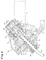
- a trailer coupling shown in FIGS. 1 and 2 is one or multi-part cross member attached to a vehicle (not shown).
- the trailer coupling comprises a cranked coupling ball at its free end 2 bearing ball rod 3, with its ball bearing head 4 between one Mounting flange 5 and in this embodiment with an interposition a shim 6 opposite connecting plate 7 is arranged is.
- the ball rod bearing head 4 is held by means of a Hollow shaft 8 (see FIGS. 3 to 5) on which the ball rod with its ball rod bearing head 4 is stored.
- a mounting bushing 9 is fitted from the outside of the mounting flange, the end part of the hub and with a bore 10 in alignment with the central Bore 11 of the hollow shaft 8 and a through hole of the mounting flange 5 is arranged trending.
- the mounting socket 9 could alternatively also be integrally formed with the hollow shaft 8, for. B. only as a hub extension of the collar 13 of the hollow shaft 8.
- the bore of the mounting flange 5 is overhanged by a flange 12 of the mounting bush 9.
- Through the flange 12 in provide a collar 13 of the hollow shaft 8 screwed fastening screws 14 for the exact positioning of the hollow shaft 8, which is furthermore due to Centering pins 15 is supported, and at the same time prevent displacement of the Hollow shaft 8.
- the hitch with its mounting flange 5 on one or multi-part cross member attached to a motor vehicle, not shown connected is.
- Fig. 1 shows that in the operating position and Fig. 2 that pivoted into the rest position Ball rod 3 of the trailer coupling 1.
- the Ball rod 3 locked non-rotatably (will be described below).
- a handwheel trigger mechanism 16 via a with a screw sleeve 17a connected to the hub of the mounting bush 9 Bowden cable 17, the end that dips into the ball rod ply head 4 with a locking pin 18 which can be moved back and forth in the hollow shaft 8 (cf. the 3 to 5) is connected.
- FIG. 3 is in the rotary end positions (operating or rest position) the ball rod 3 via a positive connection 19, which here in the mounting flange 5 arranged balls 20 and this in the end face of the Ball rod bearing head 4 there are oppositely assigned domes 21 (see FIG. 5), fixed in rotation.
- To lock these rotary end positions are for the locking pin 18 in a rear radial plane I in radial bores 22a, these are only partially recognizable in Fig. 3 because of the offset cutting plane Hollow shaft 8 a plurality of locking means in the form of balls 23a provided by the rear locking pin body 18a are pressed out and in one assigned to them in a bearing ring 24 of the ball rod bearing head 4 Recording 25a, formed for example as an annular groove or groove.
- the receptacle 25a is on its running surface facing the mounting flange 5 provided with a chamfer 26a (see also FIGS. 4 and 5), which in the the rotational end positions locked position of the ball rod 3 a targeted Force for the axial displacement of the ball rod 3 or the ball rod bearing head 4 in the direction of the mounting flange 5.
- the locking pin 18, which on its the balls 23a through the radial bores 22b into the receptacle 25a of the bearing ring 24, pressing its rear circumference Locking pin body 18a with a self-locking bevel 27 and / or an undercut is formed in this blocking position by a Force element in the form of a compression spring 28 moves in behind the locking pin the bores 11 and 10 of the hollow shaft 8, mounting flange 5 and mounting bush 9 is arranged.
- the locking pin 18 are in a second, front radial plane II in radial bores 22b of the hollow shaft 8 circumferentially distributed further locking means in Form of balls 23b and a receptacle 25b, again formed, for example assigned as an annular groove or groove.
- This front receptacle 25b is with a run-up slope 26b is formed, the one opposite to the run-up slope 26a of the front radial plane I aligned force, namely away from Mounting flange 5 causes.
- Towards the front is the trailer coupling 1 closed by a cap 29 screwed onto the free end of the hollow shaft 8.
- the locking pin 18 is actuated by actuating e.g. in one Trunk of a motor vehicle attached handwheel release mechanism 16 against the spring 28 (not shown in FIGS. 4 and 5 for the sake of simplicity), which prestresses, deferred; this retracted position of the locking pin 18 shows FIG. 4.
- actuating e.g. in one Trunk of a motor vehicle attached handwheel release mechanism 16 against the spring 28 (not shown in FIGS. 4 and 5 for the sake of simplicity), which prestresses, deferred; this retracted position of the locking pin 18 shows FIG. 4.
Applications Claiming Priority (2)
| Application Number | Priority Date | Filing Date | Title |
|---|---|---|---|
| DE10320302A DE10320302A1 (de) | 2003-05-07 | 2003-05-07 | Anhängekupplung für Kraftfahrzeuge |
| DE10320302 | 2003-05-07 |
Publications (2)
| Publication Number | Publication Date |
|---|---|
| EP1475253A1 true EP1475253A1 (fr) | 2004-11-10 |
| EP1475253B1 EP1475253B1 (fr) | 2008-04-23 |
Family
ID=32981260
Family Applications (1)
| Application Number | Title | Priority Date | Filing Date |
|---|---|---|---|
| EP04006028A Expired - Lifetime EP1475253B1 (fr) | 2003-05-07 | 2004-03-13 | Attelage de remorque pour véhicules automobiles |
Country Status (3)
| Country | Link |
|---|---|
| EP (1) | EP1475253B1 (fr) |
| AT (1) | ATE393041T1 (fr) |
| DE (2) | DE10320302A1 (fr) |
Cited By (11)
| Publication number | Priority date | Publication date | Assignee | Title |
|---|---|---|---|---|
| EP1826033A1 (fr) * | 2006-02-27 | 2007-08-29 | WESTFALIA - Automotive GmbH | Dispositif d'attelage pour véhicules automobiles |
| EP1985473A1 (fr) | 2007-04-25 | 2008-10-29 | WESTFALIA - Automotive GmbH | Attelage doté d'un dispositif d'actionnement |
| EP2130696A1 (fr) | 2008-06-06 | 2009-12-09 | WESTFALIA - Automotive GmbH | Attelage doté d'un capteur |
| EP2149460A1 (fr) | 2008-08-01 | 2010-02-03 | WESTFALIA - Automotive GmbH | Attelage |
| EP2277724A2 (fr) | 2009-07-20 | 2011-01-26 | WESTFALIA - Automotive GmbH | Attelage |
| DE202009014826U1 (de) | 2009-11-03 | 2011-03-17 | Westfalia-Automotive Gmbh | Verbindungseinrichtung für eine Anhängekupplung oder einen Lastenträger |
| EP1886847B2 (fr) † | 2006-07-29 | 2016-06-15 | Scambia Holdings Cyprus Limited | Attelage |
| EP1491369B1 (fr) | 2003-06-26 | 2019-01-16 | Bosal ACPS Holding 2 B.V. | Attelage pour vehicules |
| EP3357717B1 (fr) | 2011-11-03 | 2019-12-04 | WESTFALIA - Automotive GmbH | Attelage doté d'un dispositif d'évaluation |
| WO2020069977A1 (fr) | 2018-10-04 | 2020-04-09 | Westfalia-Automotive Gmbh | Attelage de remorque |
| DE102019106223A1 (de) * | 2018-12-12 | 2020-06-18 | Westfalia-Automotive Gmbh | Anhängekupplung sowie Verfahren zu deren Herstellung |
Families Citing this family (24)
| Publication number | Priority date | Publication date | Assignee | Title |
|---|---|---|---|---|
| DE10336445B4 (de) * | 2003-08-08 | 2006-04-20 | Westfalia-Automotive Gmbh & Co. Kg | Anhängerkupplung für Kraftfahrzeuge |
| DE10340347B4 (de) | 2003-09-02 | 2020-02-13 | Westfalia-Automotive Gmbh | Anhängerkupplung für Kraftfahrzeuge |
| DE10362419B3 (de) * | 2003-09-02 | 2021-04-22 | Westfalia-Automotive Gmbh | Anhängerkupplung für Kraftfahrzeuge |
| DE102004004503B4 (de) | 2004-01-22 | 2022-01-20 | ACPS Automotive GmbH | Anhängekupplung |
| DE102004033041A1 (de) | 2004-07-07 | 2006-02-02 | Westfalia-Automotive Gmbh & Co. Kg | Anhängekupplung für Kraftfahrzeuge |
| DE102005032474A1 (de) | 2005-07-07 | 2007-01-11 | Oris Fahrzeugteile Hans Riehle Gmbh | Anhängevorrichtung |
| DE102005047379A1 (de) * | 2005-09-28 | 2007-04-12 | Scambia Industrial Developments Aktiengesellschaft | Anhängekupplung |
| DE102007003773A1 (de) * | 2007-01-19 | 2008-07-24 | Westfalia-Automotive Gmbh | Anhängevorrichtung für ein Zugfahrzeug |
| DE102006045979A1 (de) | 2006-09-27 | 2008-04-03 | Fac Frank Abels Consulting & Technology Gesellschaft Mbh | Anhängerkupplung |
| DE102007003774A1 (de) * | 2007-01-19 | 2008-07-24 | Westfalia-Automotive Gmbh | Anhängevorrichtung mit einer Verriegelungseinrichtung mit Betätigungsring |
| DE102007041582A1 (de) * | 2007-09-01 | 2009-03-05 | Westfalia-Automotive Gmbh | Anhängekupplung |
| DE102011053506A1 (de) | 2011-09-12 | 2013-03-14 | Scambia Holdings Cyprus Ltd. | Anhängekupplung |
| DE102012011069A1 (de) | 2012-06-04 | 2013-12-05 | Westfalia-Automotive Gmbh | Betätigungssystem für eine Anhängekupplung eines Kraftfahrzeugs |
| DE102012011053A1 (de) | 2012-06-04 | 2013-12-05 | Westfalia-Automotive Gmbh | Antriebseinrichtung für einen Kugelhals einer Anhängekupplung |
| DE102012011070A1 (de) | 2012-06-04 | 2013-12-05 | Westfalia-Automotive Gmbh | Betätigungssystem für eine Anhängekupplung eines Kraftfahrzeugs |
| DE102012011054A1 (de) | 2012-06-04 | 2013-12-05 | Westfalia-Automotive Gmbh | Entriegelungseinrichtung für eine Anhängekupplung eines Kraftfahrzeugs |
| DE102012011071A1 (de) | 2012-06-04 | 2013-12-05 | Westfalia-Automotive Gmbh | Anhängekupplung für ein Kraftfahrzeug |
| DE102012024235B3 (de) * | 2012-12-12 | 2014-05-22 | Westfalia-Automotive Gmbh | Steuereinrichtung für einen schwenkbeweglichen Kugelhals |
| EP3379222B1 (fr) | 2017-03-22 | 2020-12-30 | Methode Electronics Malta Ltd. | Ensemble de capteur à base magnétoélastique |
| US11084342B2 (en) | 2018-02-27 | 2021-08-10 | Methode Electronics, Inc. | Towing systems and methods using magnetic field sensing |
| DE18907724T1 (de) | 2018-02-27 | 2021-03-25 | Methode Electronics, Inc. | Schleppsysteme und Verfahren mit Verwendung von Magnetfeldmessung |
| US11221262B2 (en) | 2018-02-27 | 2022-01-11 | Methode Electronics, Inc. | Towing systems and methods using magnetic field sensing |
| US11491832B2 (en) | 2018-02-27 | 2022-11-08 | Methode Electronics, Inc. | Towing systems and methods using magnetic field sensing |
| US11135882B2 (en) | 2018-02-27 | 2021-10-05 | Methode Electronics, Inc. | Towing systems and methods using magnetic field sensing |
Citations (9)
| Publication number | Priority date | Publication date | Assignee | Title |
|---|---|---|---|---|
| WO1997004972A1 (fr) * | 1995-08-02 | 1997-02-13 | Oris Fahrzeugteile Hans Riehle Gmbh | Dispositif d'attelage |
| DE19701273A1 (de) * | 1996-01-24 | 1997-07-31 | Westfalia Werke Knoebel | Kupplungskugelträger für Fahrzeuganhängerkupplungen |
| DE19858978A1 (de) * | 1998-12-19 | 2000-06-29 | Daimler Chrysler Ag | Schwenkbare Anhängerkupplung für Kraftfahrzeuge |
| DE19859961A1 (de) | 1998-12-29 | 2000-07-13 | Westfalia Werke Gmbh & Co | Anhängerkupplung mit einem schwenkbaren Kugelhals |
| EP1024036A1 (fr) * | 1999-01-21 | 2000-08-02 | ORIS FAHRZEUGTEILE HANS RIEHLE GmbH | Attelage de remorque |
| EP1142732A2 (fr) * | 2000-04-05 | 2001-10-10 | ORIS FAHRZEUGTEILE HANS RIEHLE GmbH | Attelage de remorque |
| DE10032002A1 (de) * | 2000-06-30 | 2002-01-24 | Oris Fahrzeugteile Riehle H | Anhängevorrichtung |
| EP1182062A2 (fr) * | 1998-10-21 | 2002-02-27 | ORIS FAHRZEUGTEILE HANS RIEHLE GmbH | Attelage de remorque |
| EP1288026A1 (fr) * | 2001-09-03 | 2003-03-05 | ORIS FAHRZEUGTEILE HANS RIEHLE GmbH | Attelage de remorque |
-
2003
- 2003-05-07 DE DE10320302A patent/DE10320302A1/de not_active Withdrawn
-
2004
- 2004-03-13 AT AT04006028T patent/ATE393041T1/de not_active IP Right Cessation
- 2004-03-13 DE DE502004006879T patent/DE502004006879D1/de not_active Expired - Lifetime
- 2004-03-13 EP EP04006028A patent/EP1475253B1/fr not_active Expired - Lifetime
Patent Citations (9)
| Publication number | Priority date | Publication date | Assignee | Title |
|---|---|---|---|---|
| WO1997004972A1 (fr) * | 1995-08-02 | 1997-02-13 | Oris Fahrzeugteile Hans Riehle Gmbh | Dispositif d'attelage |
| DE19701273A1 (de) * | 1996-01-24 | 1997-07-31 | Westfalia Werke Knoebel | Kupplungskugelträger für Fahrzeuganhängerkupplungen |
| EP1182062A2 (fr) * | 1998-10-21 | 2002-02-27 | ORIS FAHRZEUGTEILE HANS RIEHLE GmbH | Attelage de remorque |
| DE19858978A1 (de) * | 1998-12-19 | 2000-06-29 | Daimler Chrysler Ag | Schwenkbare Anhängerkupplung für Kraftfahrzeuge |
| DE19859961A1 (de) | 1998-12-29 | 2000-07-13 | Westfalia Werke Gmbh & Co | Anhängerkupplung mit einem schwenkbaren Kugelhals |
| EP1024036A1 (fr) * | 1999-01-21 | 2000-08-02 | ORIS FAHRZEUGTEILE HANS RIEHLE GmbH | Attelage de remorque |
| EP1142732A2 (fr) * | 2000-04-05 | 2001-10-10 | ORIS FAHRZEUGTEILE HANS RIEHLE GmbH | Attelage de remorque |
| DE10032002A1 (de) * | 2000-06-30 | 2002-01-24 | Oris Fahrzeugteile Riehle H | Anhängevorrichtung |
| EP1288026A1 (fr) * | 2001-09-03 | 2003-03-05 | ORIS FAHRZEUGTEILE HANS RIEHLE GmbH | Attelage de remorque |
Cited By (19)
| Publication number | Priority date | Publication date | Assignee | Title |
|---|---|---|---|---|
| EP1491369B1 (fr) | 2003-06-26 | 2019-01-16 | Bosal ACPS Holding 2 B.V. | Attelage pour vehicules |
| EP1970224A1 (fr) | 2006-02-27 | 2008-09-17 | WESTFALIA - Automotive GmbH | Attelage pour véhicules automobiles |
| EP1826033A1 (fr) * | 2006-02-27 | 2007-08-29 | WESTFALIA - Automotive GmbH | Dispositif d'attelage pour véhicules automobiles |
| EP1886847B2 (fr) † | 2006-07-29 | 2016-06-15 | Scambia Holdings Cyprus Limited | Attelage |
| EP1985473A1 (fr) | 2007-04-25 | 2008-10-29 | WESTFALIA - Automotive GmbH | Attelage doté d'un dispositif d'actionnement |
| DE102008034850A1 (de) | 2008-06-06 | 2009-12-17 | Westfalia-Automotive Gmbh | Anhängekupplung mit einem Sensor |
| EP2130696A1 (fr) | 2008-06-06 | 2009-12-09 | WESTFALIA - Automotive GmbH | Attelage doté d'un capteur |
| EP2149460A1 (fr) | 2008-08-01 | 2010-02-03 | WESTFALIA - Automotive GmbH | Attelage |
| DE102008035987A1 (de) | 2008-08-01 | 2010-02-04 | Westfalia-Automotive Gmbh | Anhängekupplung |
| EP2277724A2 (fr) | 2009-07-20 | 2011-01-26 | WESTFALIA - Automotive GmbH | Attelage |
| DE102009033911A1 (de) | 2009-07-20 | 2011-01-27 | Westfalia-Automotive Gmbh | Anhängekupplung |
| DE202009014826U1 (de) | 2009-11-03 | 2011-03-17 | Westfalia-Automotive Gmbh | Verbindungseinrichtung für eine Anhängekupplung oder einen Lastenträger |
| DE102010049384A1 (de) | 2009-11-03 | 2011-05-05 | Westfalia-Automotive Gmbh | Verbindungseinrichtung für eine Anhängekupplung oder einen Lastenträger |
| EP2316673A1 (fr) | 2009-11-03 | 2011-05-04 | WESTFALIA - Automotive GmbH | Dispositif de liaison pour un attelage ou un support de charge |
| EP3357717B1 (fr) | 2011-11-03 | 2019-12-04 | WESTFALIA - Automotive GmbH | Attelage doté d'un dispositif d'évaluation |
| EP3357717B2 (fr) † | 2011-11-03 | 2023-11-22 | WESTFALIA - Automotive GmbH | Attelage doté d'un dispositif d'évaluation |
| WO2020069977A1 (fr) | 2018-10-04 | 2020-04-09 | Westfalia-Automotive Gmbh | Attelage de remorque |
| DE102018124549A1 (de) * | 2018-10-04 | 2020-04-09 | Westfalia-Automotive Gmbh | Anhängekupplung |
| DE102019106223A1 (de) * | 2018-12-12 | 2020-06-18 | Westfalia-Automotive Gmbh | Anhängekupplung sowie Verfahren zu deren Herstellung |
Also Published As
| Publication number | Publication date |
|---|---|
| DE10320302A1 (de) | 2004-12-09 |
| DE502004006879D1 (de) | 2008-06-05 |
| EP1475253B1 (fr) | 2008-04-23 |
| ATE393041T1 (de) | 2008-05-15 |
Similar Documents
| Publication | Publication Date | Title |
|---|---|---|
| EP1475253A1 (fr) | Attelage de remorque pour véhicules automobiles | |
| EP1504928B1 (fr) | Attache remorque | |
| EP1428697B1 (fr) | Dipositif d'attelage | |
| EP1533149B1 (fr) | Attelage pour vehicules | |
| EP2567836B2 (fr) | Attelage | |
| EP1757466B1 (fr) | Attelage pour véhicules | |
| EP1561610B1 (fr) | Mecanisme d'attelage | |
| EP3135574B1 (fr) | Couplage | |
| DE102013008652A1 (de) | Vorrichtung zur Sturz- und/oder Spurverstellung eines Fahrzeugrades | |
| DE3831807C2 (fr) | ||
| DE102007043984A1 (de) | Elektromotorischer Linearantrieb | |
| DE19945255A1 (de) | Radlagerung, insbesondere für nichtangetriebene Fahrzeugachsen | |
| EP1491369B1 (fr) | Attelage pour vehicules | |
| EP1614556B1 (fr) | Attelage de remorque pour véhicules automobiles | |
| EP1634730A1 (fr) | Attelage de remorque avec articulation à rotule | |
| DE3619756C2 (fr) | ||
| EP2829422B1 (fr) | Système d'attelage pour véhicules automobiles | |
| DE102005061254B4 (de) | Fahrzeugsitz | |
| DE102004039253B4 (de) | Haltevorrichtung für einen Bowdenzug sowie Fahrzeugsitz | |
| DE3441558C2 (fr) | ||
| DE10340347B4 (de) | Anhängerkupplung für Kraftfahrzeuge | |
| EP1621371B1 (fr) | Attelage de remorque pour véhicules automobiles | |
| DE60302337T2 (de) | Entriegelungsvorrichtung für verriegelungseinrichtung für einen radbolzen | |
| DE1605465C (de) | Feststellvorrichtung fur an verfahrbaren Gegenstanden anzu bringende Lenkrollen | |
| DE1580028C3 (de) | Steckbolzen für eine Anhängerkupplung, insbesondere für landwirtschaftlich nutzbare Fahrzeuge |
Legal Events
| Date | Code | Title | Description |
|---|---|---|---|
| PUAI | Public reference made under article 153(3) epc to a published international application that has entered the european phase |
Free format text: ORIGINAL CODE: 0009012 |
|
| AK | Designated contracting states |
Kind code of ref document: A1 Designated state(s): AT BE BG CH CY CZ DE DK EE ES FI FR GB GR HU IE IT LI LU MC NL PL PT RO SE SI SK TR |
|
| AX | Request for extension of the european patent |
Extension state: AL LT LV MK |
|
| 17P | Request for examination filed |
Effective date: 20050429 |
|
| AKX | Designation fees paid |
Designated state(s): AT BE BG CH CY CZ DE DK EE ES FI FR GB GR HU IE IT LI LU MC NL PL PT RO SE SI SK TR |
|
| RAP1 | Party data changed (applicant data changed or rights of an application transferred) |
Owner name: WESTFALIA - AUTOMOTIVE GMBH |
|
| 17Q | First examination report despatched |
Effective date: 20061121 |
|
| GRAP | Despatch of communication of intention to grant a patent |
Free format text: ORIGINAL CODE: EPIDOSNIGR1 |
|
| GRAS | Grant fee paid |
Free format text: ORIGINAL CODE: EPIDOSNIGR3 |
|
| GRAA | (expected) grant |
Free format text: ORIGINAL CODE: 0009210 |
|
| AK | Designated contracting states |
Kind code of ref document: B1 Designated state(s): AT BE BG CH CY CZ DE DK EE ES FI FR GB GR HU IE IT LI LU MC NL PL PT RO SE SI SK TR |
|
| REG | Reference to a national code |
Ref country code: GB Ref legal event code: FG4D Free format text: NOT ENGLISH |
|
| REG | Reference to a national code |
Ref country code: CH Ref legal event code: EP |
|
| REF | Corresponds to: |
Ref document number: 502004006879 Country of ref document: DE Date of ref document: 20080605 Kind code of ref document: P |
|
| REG | Reference to a national code |
Ref country code: IE Ref legal event code: FG4D Free format text: LANGUAGE OF EP DOCUMENT: GERMAN |
|
| PG25 | Lapsed in a contracting state [announced via postgrant information from national office to epo] |
Ref country code: SI Free format text: LAPSE BECAUSE OF FAILURE TO SUBMIT A TRANSLATION OF THE DESCRIPTION OR TO PAY THE FEE WITHIN THE PRESCRIBED TIME-LIMIT Effective date: 20080423 |
|
| NLV1 | Nl: lapsed or annulled due to failure to fulfill the requirements of art. 29p and 29m of the patents act | ||
| PG25 | Lapsed in a contracting state [announced via postgrant information from national office to epo] |
Ref country code: PT Free format text: LAPSE BECAUSE OF FAILURE TO SUBMIT A TRANSLATION OF THE DESCRIPTION OR TO PAY THE FEE WITHIN THE PRESCRIBED TIME-LIMIT Effective date: 20080923 Ref country code: ES Free format text: LAPSE BECAUSE OF FAILURE TO SUBMIT A TRANSLATION OF THE DESCRIPTION OR TO PAY THE FEE WITHIN THE PRESCRIBED TIME-LIMIT Effective date: 20080803 Ref country code: NL Free format text: LAPSE BECAUSE OF FAILURE TO SUBMIT A TRANSLATION OF THE DESCRIPTION OR TO PAY THE FEE WITHIN THE PRESCRIBED TIME-LIMIT Effective date: 20080423 Ref country code: BG Free format text: LAPSE BECAUSE OF FAILURE TO SUBMIT A TRANSLATION OF THE DESCRIPTION OR TO PAY THE FEE WITHIN THE PRESCRIBED TIME-LIMIT Effective date: 20080723 Ref country code: FI Free format text: LAPSE BECAUSE OF FAILURE TO SUBMIT A TRANSLATION OF THE DESCRIPTION OR TO PAY THE FEE WITHIN THE PRESCRIBED TIME-LIMIT Effective date: 20080423 |
|
| PG25 | Lapsed in a contracting state [announced via postgrant information from national office to epo] |
Ref country code: PL Free format text: LAPSE BECAUSE OF FAILURE TO SUBMIT A TRANSLATION OF THE DESCRIPTION OR TO PAY THE FEE WITHIN THE PRESCRIBED TIME-LIMIT Effective date: 20080423 |
|
| REG | Reference to a national code |
Ref country code: IE Ref legal event code: FD4D |
|
| ET | Fr: translation filed | ||
| PG25 | Lapsed in a contracting state [announced via postgrant information from national office to epo] |
Ref country code: IE Free format text: LAPSE BECAUSE OF FAILURE TO SUBMIT A TRANSLATION OF THE DESCRIPTION OR TO PAY THE FEE WITHIN THE PRESCRIBED TIME-LIMIT Effective date: 20080423 Ref country code: CZ Free format text: LAPSE BECAUSE OF FAILURE TO SUBMIT A TRANSLATION OF THE DESCRIPTION OR TO PAY THE FEE WITHIN THE PRESCRIBED TIME-LIMIT Effective date: 20080423 Ref country code: DK Free format text: LAPSE BECAUSE OF FAILURE TO SUBMIT A TRANSLATION OF THE DESCRIPTION OR TO PAY THE FEE WITHIN THE PRESCRIBED TIME-LIMIT Effective date: 20080423 Ref country code: SE Free format text: LAPSE BECAUSE OF FAILURE TO SUBMIT A TRANSLATION OF THE DESCRIPTION OR TO PAY THE FEE WITHIN THE PRESCRIBED TIME-LIMIT Effective date: 20080723 |
|
| PG25 | Lapsed in a contracting state [announced via postgrant information from national office to epo] |
Ref country code: RO Free format text: LAPSE BECAUSE OF FAILURE TO SUBMIT A TRANSLATION OF THE DESCRIPTION OR TO PAY THE FEE WITHIN THE PRESCRIBED TIME-LIMIT Effective date: 20080423 Ref country code: SK Free format text: LAPSE BECAUSE OF FAILURE TO SUBMIT A TRANSLATION OF THE DESCRIPTION OR TO PAY THE FEE WITHIN THE PRESCRIBED TIME-LIMIT Effective date: 20080423 |
|
| PLBE | No opposition filed within time limit |
Free format text: ORIGINAL CODE: 0009261 |
|
| STAA | Information on the status of an ep patent application or granted ep patent |
Free format text: STATUS: NO OPPOSITION FILED WITHIN TIME LIMIT |
|
| 26N | No opposition filed |
Effective date: 20090126 |
|
| PG25 | Lapsed in a contracting state [announced via postgrant information from national office to epo] |
Ref country code: EE Free format text: LAPSE BECAUSE OF FAILURE TO SUBMIT A TRANSLATION OF THE DESCRIPTION OR TO PAY THE FEE WITHIN THE PRESCRIBED TIME-LIMIT Effective date: 20080423 |
|
| PG25 | Lapsed in a contracting state [announced via postgrant information from national office to epo] |
Ref country code: IT Free format text: LAPSE BECAUSE OF FAILURE TO SUBMIT A TRANSLATION OF THE DESCRIPTION OR TO PAY THE FEE WITHIN THE PRESCRIBED TIME-LIMIT Effective date: 20080423 |
|
| BERE | Be: lapsed |
Owner name: WESTFALIA - AUTOMOTIVE G.M.B.H. Effective date: 20090331 |
|
| PG25 | Lapsed in a contracting state [announced via postgrant information from national office to epo] |
Ref country code: MC Free format text: LAPSE BECAUSE OF NON-PAYMENT OF DUE FEES Effective date: 20090331 |
|
| REG | Reference to a national code |
Ref country code: CH Ref legal event code: PL |
|
| GBPC | Gb: european patent ceased through non-payment of renewal fee |
Effective date: 20090313 |
|
| PG25 | Lapsed in a contracting state [announced via postgrant information from national office to epo] |
Ref country code: LI Free format text: LAPSE BECAUSE OF NON-PAYMENT OF DUE FEES Effective date: 20090331 Ref country code: CH Free format text: LAPSE BECAUSE OF NON-PAYMENT OF DUE FEES Effective date: 20090331 |
|
| PG25 | Lapsed in a contracting state [announced via postgrant information from national office to epo] |
Ref country code: BE Free format text: LAPSE BECAUSE OF NON-PAYMENT OF DUE FEES Effective date: 20090331 |
|
| PG25 | Lapsed in a contracting state [announced via postgrant information from national office to epo] |
Ref country code: GB Free format text: LAPSE BECAUSE OF NON-PAYMENT OF DUE FEES Effective date: 20090313 |
|
| PG25 | Lapsed in a contracting state [announced via postgrant information from national office to epo] |
Ref country code: AT Free format text: LAPSE BECAUSE OF NON-PAYMENT OF DUE FEES Effective date: 20090313 |
|
| PG25 | Lapsed in a contracting state [announced via postgrant information from national office to epo] |
Ref country code: GR Free format text: LAPSE BECAUSE OF FAILURE TO SUBMIT A TRANSLATION OF THE DESCRIPTION OR TO PAY THE FEE WITHIN THE PRESCRIBED TIME-LIMIT Effective date: 20080724 |
|
| PG25 | Lapsed in a contracting state [announced via postgrant information from national office to epo] |
Ref country code: LU Free format text: LAPSE BECAUSE OF NON-PAYMENT OF DUE FEES Effective date: 20090313 |
|
| PG25 | Lapsed in a contracting state [announced via postgrant information from national office to epo] |
Ref country code: HU Free format text: LAPSE BECAUSE OF FAILURE TO SUBMIT A TRANSLATION OF THE DESCRIPTION OR TO PAY THE FEE WITHIN THE PRESCRIBED TIME-LIMIT Effective date: 20081024 |
|
| PG25 | Lapsed in a contracting state [announced via postgrant information from national office to epo] |
Ref country code: TR Free format text: LAPSE BECAUSE OF FAILURE TO SUBMIT A TRANSLATION OF THE DESCRIPTION OR TO PAY THE FEE WITHIN THE PRESCRIBED TIME-LIMIT Effective date: 20080423 |
|
| PG25 | Lapsed in a contracting state [announced via postgrant information from national office to epo] |
Ref country code: CY Free format text: LAPSE BECAUSE OF FAILURE TO SUBMIT A TRANSLATION OF THE DESCRIPTION OR TO PAY THE FEE WITHIN THE PRESCRIBED TIME-LIMIT Effective date: 20080423 |
|
| REG | Reference to a national code |
Ref country code: FR Ref legal event code: PLFP Year of fee payment: 13 |
|
| REG | Reference to a national code |
Ref country code: FR Ref legal event code: PLFP Year of fee payment: 14 |
|
| REG | Reference to a national code |
Ref country code: FR Ref legal event code: PLFP Year of fee payment: 15 |
|
| PGFP | Annual fee paid to national office [announced via postgrant information from national office to epo] |
Ref country code: FR Payment date: 20230320 Year of fee payment: 20 |
|
| PGFP | Annual fee paid to national office [announced via postgrant information from national office to epo] |
Ref country code: DE Payment date: 20230109 Year of fee payment: 20 |
|
| REG | Reference to a national code |
Ref country code: DE Ref legal event code: R071 Ref document number: 502004006879 Country of ref document: DE |