EP2711207A2 - Spherical swivel module - Google Patents
Spherical swivel module Download PDFInfo
- Publication number
- EP2711207A2 EP2711207A2 EP13180798.4A EP13180798A EP2711207A2 EP 2711207 A2 EP2711207 A2 EP 2711207A2 EP 13180798 A EP13180798 A EP 13180798A EP 2711207 A2 EP2711207 A2 EP 2711207A2
- Authority
- EP
- European Patent Office
- Prior art keywords
- ball
- locking
- spindle
- module
- pin
- Prior art date
- Legal status (The legal status is an assumption and is not a legal conclusion. Google has not performed a legal analysis and makes no representation as to the accuracy of the status listed.)
- Withdrawn
Links
Images


Classifications
-
- B—PERFORMING OPERATIONS; TRANSPORTING
- B60—VEHICLES IN GENERAL
- B60D—VEHICLE CONNECTIONS
- B60D1/00—Traction couplings; Hitches; Draw-gear; Towing devices
- B60D1/48—Traction couplings; Hitches; Draw-gear; Towing devices characterised by the mounting
- B60D1/54—Traction couplings; Hitches; Draw-gear; Towing devices characterised by the mounting collapsible or retractable when not in use, e.g. hide-away hitches
-
- F—MECHANICAL ENGINEERING; LIGHTING; HEATING; WEAPONS; BLASTING
- F16—ENGINEERING ELEMENTS AND UNITS; GENERAL MEASURES FOR PRODUCING AND MAINTAINING EFFECTIVE FUNCTIONING OF MACHINES OR INSTALLATIONS; THERMAL INSULATION IN GENERAL
- F16C—SHAFTS; FLEXIBLE SHAFTS; ELEMENTS OR CRANKSHAFT MECHANISMS; ROTARY BODIES OTHER THAN GEARING ELEMENTS; BEARINGS
- F16C11/00—Pivots; Pivotal connections
- F16C11/04—Pivotal connections
- F16C11/10—Arrangements for locking
Definitions
- the invention relates to a ball pivot module for a trailer hitch according to the preamble of claim 1.
- a switching pin prevents after unlocking, which recoils the locking bolt by the force of a spring in the locked position.
- a ball pivoting module in particular for a trailer hitch, which has a ball pin, which ball pin comprises a ball joint and is mounted in a housing, wherein in the ball pin a recess is provided, in which a locking pin is arranged axially displaceable to a substantially vertical to actuate the locking pin movable means for locking and unlocking the ball pivot module, wherein a drive is provided for the motorized actuation of the locking pin, in particular an electric motor, wherein the drive is coupled via a compound of axially rigid elements with the locking pin.
- the ball pivoting module is characterized in that the drive and the said connection are adapted to move the locking pin within the recess by a motor to its locking position and thereby to actuate the means for locking the ball pivot module.
- the recess may be formed as a particular through hole, preferably bore koxial to the longitudinal axis of the ball stud.
- the means for locking may be formed of locking elements or locking units consisting of at least one ball or also a combination of balls, split rings and hollow or solid cylindrical members which move approximately transversely to the longitudinal axis of the ball stud in suitable tracks.
- the rigid connection comprises a first rigid element, which first rigid element is coupled to the drive, and a second rigid element, which second rigid element is coupled to the locking bolt.
- the first rigid element may be a gear and the second rigid element may be a spindle, wherein preferably the gear is arranged substantially concentrically around the spindle longitudinal axis of the spindle and cooperating with the spindle.
- a spindle, in particular threaded spindle is a round rod-shaped machine element which, together with other elements, converts a rotary movement into a translational movement, wherein a thread, e.g. a trapezoidal thread is formed.
- the spindle preferably extends within the recess of the ball pin and is non-positively and / or positively or materially coupled to the locking pin.
- the proposed drive (electric motor) transmits a rotational movement to the gearwheel directly or by means of a separate drive shaft or a drive pinion. If the gear wheel and the spindle are coupled to one another via a positive connection, then the interaction of gear wheel and spindle causes the translatory drive of the locking bolt.
- the spindle position can also be determined directly by sensors, wherein at least one first sensor is used.
- the invention is not limited to the use of a particular type of sensor.
- a button can be used to query the spindle position.
- Other usable sensors are based on inductive, capacitive or optical and thus non-contact principles of action. Especially for the determination of the spindle position and so-called. Linear sensors can be used to determine a wear of the assembly and possibly replace the ball pivot module.
- the gear has a first thread, in particular an internal thread
- the spindle has a second thread, in particular an external thread, which are in operative connection, in particular meshing engagement.
- the gear is driven by said drive or motor, preferably an electric motor, which eliminates the need for manual (manual) operation and greatly enhances user comfort.
- the spindle and the locking pin are non-positively and / or positively or materially preferably connected via a snap ring and associated latching structures, in particular a groove on the spindle or locking pin.
- a spindle end in a corresponding receptacle may be held in the locking pin, but without the invention would be limited to locking pin with a blind hole.
- the connection via a snap ring and the associated Verrast Modellen allows some movement of the spindle relative to the locking pin in a determined by the arrangement of snap ring and Verrast Modellen stroke within said recording and depending on their depth. This allows the spindle to assume a rest position during trailer operation, without having to absorb loads that are introduced via the locking pin.
- the ball pivot module additionally has a (central) pressure spring, as it is already known from the prior art.
- the spring may be arranged around the spindle within the recess of the ball stud.
- the drive via the spindle and the locking pin provides for the desired locking by the locking pin is moved in the recess as far as possible in its locking position, wherein it actuates the means for locking the ball pivot module.
- a second sensor which detects the position (rotational position) of a further gear, wherein the further gear is coupled to the housing of the ball pivot module, so that on the position of this gear and the position of the housing and consequently the position of a ball bar connected to the housing is detectable.
- the second sensor for detecting the pivot position may, for example, a button, an inductive sensor, a capacitive sensor, a Hall sensor, a magnetostrictive sensor or the like non-contact sensor, which detects the position of the gear.
- Said gear can for this purpose have certain structures to which the sensor responds, for example, projections or protrusions, recesses, permanent magnets used, optical markings or the like, depending on the sensor type used. Since the position of the further gear is coupled via the mechanism of the ball pivot module to the position of the housing, the first sensor thus indirectly detects the position of the housing. It should be emphasized that in this further gear is basically a different gear than that gear, which is used to drive the spindle and thus to effect the unlocking / locking.
- the other gear is used to effect a rotational-tilting movement of the ball rod, however, for example, corresponds to the pivoted-out operating position of the ball bar just the aforementioned locking position of the locking pin, so that the further gear can also be used to determine the locking position of the locking pin.
- the second sensor detects a first position of the further gear, which corresponds to an operating position of a trailer hook provided on the ball pivot module (ball bar), and a second position of the further gear, which corresponds to a rest position of the trailer hook.
- the trailer hook is rigidly connected to the housing of the ball pivot module. This results from the position of the housing, the position of the trailer hook.
- the position of the housing and thus also the position of the trailer hook or the ball rod can be indirectly detected via the position of the further gear.
- the first position and the second position which are preferably offset by approximately 180 ° to each other, which thus - without restriction - corresponds to half a rotation of the other gear, respectively a locking position, ie a rest position with swiveled ball rod and a Operating or safety position with swiveled out ball rod.
- a locking position ie a rest position with swiveled ball rod
- a Operating or safety position with swiveled out ball rod.
- the further gear which is preferably rotatably mounted on the ball pivot, can be used - as also described above. This can effectively prevent a false lock.
- the pivoting can go a bit beyond the first and / or second position, after the signal for reaching the rest or operating position has already been given by the first and / or second sensor. If then the ball pivot module to be locked, the locking unit can not retract completely. Now, when a turn is pivoted back, the locks audibly engage, which increases the reliability and improves the function control. Alternatively, the pivoting may even stop slightly before reaching the mentioned positions. Then the lock is activated, and the module is then pivoted further or at the same time. As a result, a tension of the system can be achieved.
- the first sensor can also be designed as a button, inductive sensor, capacitive sensor, Hall sensor or magnetostrictive or optical sensor and queries the position of the spindle. With a defined immersion depth in the ball stud a safe locking state can be detected. Only when this condition is reached is a complete interlock signaled, e.g. by an optical or acoustic signal.
- the housing is pivotally mounted around the ball stud, which housing in turn is connected to the ball bar.
- Housing and ball bar are with respect to a rotational movement about the longitudinal axis of the ball pin, which rotational movement is preferably effected by the said further gear, coupled.
- With respect to a tilting movement about a substantially vertical tilting axis is the movement of the Longitudinal axis decoupled.
- the ball joint of the ball stud for this purpose on a non-planar control surface which is in engagement with a provided on or in the housing control element, in particular with a positive guide pin, so that this system causes a positive guidance of the ball stud in which the ball pin is rotated during a movement between the operating position and the rest position about the axis of rotation and also the housing is tilted about the tilt axis.
- This configuration provides a space-saving solution for creating a pivot module, which can perform the aforementioned rotation-tilting movement.
- Fig. 1 is a perspective view of a trailer hitch 1 with a ball pivot module 2 according to one embodiment.
- the trailer hitch 1 is arranged on a cross pipe 4, on which also a longitudinal connection 3 is provided for attachment to a vehicle and cable 5 and plug 6 to supply a likewise arranged on the cross tube 4 drive 7 in the form of at least one electric motor with energy.
- a connector 32 for connecting the two components is arranged between the drive 7 and the swivel module 2.
- a pivotable ball rod 8 tilte. with a coupling ball 9 is provided on the swivel module 2.
- the drive 7 comprises, in addition to the already mentioned electric motor, which provides for the unlocking and locking of the ball bar or the swivel module, yet another electric motor, which is responsible for the pivotal movement of the trailer hitch 1. This will be discussed in more detail below.
- Fig. 2 shows two 90 ° rotated against each other sectional views of a ball pivot module 2 with locking and unlocking according to the prior art for the purpose of a better understanding of the invention.
- a central spring (compression spring) 43 and a locking pin 44 are arranged for locking and unlocking according to the prior art.
- the Locking bolt 44 is guided in the longitudinal direction of the recess 42 within this displaceable.
- a circular-cylindrical guide channel 45 is provided in a joint ball 10 of the ball pivot module 2, which is open towards the recess 42 and extends through the wall of the joint ball 10 in a guide direction extending transversely to the longitudinal direction.
- a device for locking and unlocking the pivot module which comprises a ball 61 and a guide pin 46 which is or in the guide direction within the bore 42 extending transversely to the bore or are.
- the ball 61 acts with a working surface 47 (see FIG. 3 ) of the locking pin 44, which is oriented obliquely to the longitudinal direction.
- the locking pin 44 is pressed to lock by means of the central spring 43 in the longitudinal direction by the spring 43 downwards in the direction of ball 10. Due to the inclined working surface 47 (see FIG. 3 ) thereby the ball 61 and corresponding to the guide pin 46 in the guide direction is pressed radially outward into a trough-shaped locking recess 12a in a housing 12 of the ball pivot module 2.
- the locking recess 12a is formed by a locking insert 12b fixed in the housing 12, in which a pressure pin 48 is provided, which presses by means of a compression spring 49 against the guide pin 46 in the direction of the longitudinal extent of the guide channel 45. Since the guide pin 46 engages both in the guide channel 45 and in the locking recess 12 a, the ball joint 10 is rigidly fixed in the housing 12. When the locking pin 44 moves up again and the ball 61 correspondingly radially inwardly from the guide pin 46, the locking pin 44 is in the release position, in which the guide pin 46 by the pressurized by the compression spring 49 pressure pin 48 from the Arretsammlungsaushyroidung 12a is disengaged. The ball joint 10 is then no longer locked by the guide pin 46 in the housing 12 and can move relative thereto.
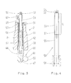
- Fig. 3 shows a section through a ball pivot module 2 for explaining an embodiment of the locking and unlocking function according to the invention.
- a spindle 50 is provided, which can move linearly in a recess 42 of the ball stud 11 up and down.
- the electric motor has an in FIG. 3 not shown shaft connected to the gear 34 so that the gear 34 performs a rotational movement about a central axis 37 corresponding to the spindle longitudinal axis 37.
- the toothed wheel 34 has a trapezoidal internal thread 57, which is not shown in detail here, and which fits into a trapezoidal external thread 56 of the spindle 50, which is likewise not shown in detail.
- the spindle 50 is connected to the locking pin 44 and locks or unlocks the locking system by pushing or pulling the locking pin 44.
- the locking pin 44 actuates a locking device 60.
- the locking device 60 acts as a substantially perpendicular to the locking pin 44 movable means for locking and unlocking and comprises a ball 61.
- a sensor 62 detects it on the basis of a lateral recess 63 of the spindle 50 whose position. Depending on the direction of rotation, the spindle 50 presses the locking pin 44 into the housing 12 or pulls it out.
- the ball 61 of the locking device 60 is analogous FIG. 2 on a working surface 47 of the locking bolt 44, which is formed as a recess in the locking bolt 44.
- the Sensor 62 detects the recess 63 of the spindle 50 or its limitations and consequently at least the switching point 54. On the position of the recess 63 relative to the sensor 62 thus the position of the spindle 50 relative to the ball pin 11 and thus the locking position can be detected.
- Fig. 4 shows a detailed view of a spindle 50, which is identical or at least similar to the spindle in Fig. 3 is constructed.
- the spindle 50 is provided at its outer periphery 55 with the already mentioned external thread 56, which extends over a length L.
- the locking device 51 is arranged on the spindle 50.
- gear 34 causes the locking device 51 that the spindle 50 performs a linear movement along the axis of rotation 37 of the gear 34 within the recess 42, as described above, depending on the direction of rotation of the gear 34th
- Fig. 5 shows a sectional view of the gear 34, which is here recognizable with the mentioned internal thread 57 is provided.
- the internal thread 57 is in positive engagement with the external thread 56 of the spindle.
- the gear 34 rotates about the axis of rotation 37 and acts as a spindle nut.
- Fig. 6 shows a detailed view of the locking bolt 44, which is provided with a cylindrical recess 58 in the manner of a blind hole, in which or which the spindle 50 is immersed.
- a latching structure 64 is formed, which cooperates with a snap ring 59.
- the spindle 50 and the locking pin 44 are relative to each other over a certain stroke range H along the axis 37 movable until the spindle end abuts the bottom of the blind hole. In this way, an optimally rigid, unyielding locking can be achieved.
- a pressure spring (not shown) can additionally be arranged within the recess 42 and around the spindle 50. Then it is possible, the spindle according to FIG. 6 after reaching optimal locking a piece far out of the locking pin 44, so that then the lock is held only or additionally by the compression spring. This results in a certain mechanical decoupling of the spindle 50 and the locking bolt 44, whereby advantageously not all forces acting on the ball rod forces also act directly on the drive train for the locking.
- Fig. 7 is a perspective view of an entire ball pivot module 2 including the components of the FIGS. 3 to 6 , As can be seen here, a tilting axis 41 of the ball pivoting module 2 is arranged offset by 90 ° relative to a driving pin 36. This makes it possible that a tilting movement about the axis 41 can be performed without the driving pin 36 tilted in a receiving device 40, also shown, since he can dip in and out of the tilting movement in this. On the elements 36 and 41 will be described below with reference to FIGS. 8A to E discussed in more detail. Furthermore, here the axis of rotation 37 can be seen, about which the ball pin 11 is rotatable. These features relating to a rotational / tilting movement of the ball pivot module or the ball rod can also be realized accordingly in the context of the present invention.
- the drive shaft 23 is formed as a two-toothed shaft and is engaged with the gear 34 '.
- the shaft 23 is part of a drive unit 33 and comprises a gear 34 ', which is formed with a partial toothing with a plurality of teeth 35. In the illustrated example, the ratio of the number of teeth is about 1:12.
- the gear 34 ' is fixedly arranged in a region without teeth of the aforementioned driving pin 36, which is specifically in Figure 8A is shown.
- the driving pin 36 is pressed into the gear 34 'and acts as a driver for the locking ring 22, which the housing 12 (see. FIG. 7 ) Closes on one side and thus rotatably connect to the housing.
- the gear 34 ' is rotatably mounted in an intermediate ring 38 which on the ball pin 11 (analog FIG. 2 ) of the ball pivot module 2 is pressed.
- a race 30 is shown, via which a seal, not shown, can be rotatably connected to the housing 12.
- the locking ring 22 is shown in more detail.
- the locking ring 22 has a receiving device 40, in which the driving pin 36 in the assembled state, which in Figure 8E is shown, is received and in which the driving pin 36 axially relative to its own longitudinal extent and radially relative to the locking ring 22 reciprocally movable when the housing 12 together with the locking ring 22 pivots about the ball pivot (axis 41, see. Fig. 7 ).
- the intermediate ring 38 is provided with a bore 39, which in FIG. 8B is shown. Through the bore 39, the output shaft 23 can be guided in the assembled state, as in Figure 8D is recognizable.
- An electric motor drives the output shaft 23 designed as a two-toothed shaft.
- the output shaft 23 drives the gear 34 ', which is rotatably mounted on the intermediate ring 38.
- the driving pin 36 is fixedly connected to the gear 34 '. By the rotation of the gear 34 'of the driving pin 36 is moved. It engages in the receiving device 40 of the closure ring 22, whereby a rotational movement of the housing 12 and thus the ball bar 8 (see FIG. 1 ) is produced.
- the closure ring 22 carries out together with the joint ball 10 of the ball pin 11 from a rotational movement. The additional tilting movement of the housing or the ball rod arises from the rotational movement through the Wirverbindg.
- Fig. 9 shows a perspective view of the gear 34 'according to the FIGS. 8A to E ,
- the gear 34 ' has a partial toothing 35.
- a circumferential semi-circular elevation 65 is arranged on an upper side of the gear 34 '.
- the ends of the elevation 65 provide landmarks for detection of the position of the gear 34 'with a sensor (not shown) as described above.
- the starting point P1 of the increase 65 corresponds to a first position, in particular, the operating position of the ball rod 8
- the end point P2 of the increase 65 corresponds to a second position, in particular the rest position of the ball rod 8.
- a corresponding sensor signal can thus be used to display these positions.
- the invention is in principle not limited to a specific sensor type.
Abstract
Description
Die Erfindung betrifft ein Kugelschwenkmodul für eine Anhängerkupplung gemäß dem Oberbegriff des Anspruchs 1.The invention relates to a ball pivot module for a trailer hitch according to the preamble of claim 1.
Im Stand der Technik sind viele Ankopplungsvarianten für Anhängerkupplungen bekannt, um sie an einem Fahrzeug zu befestigen. Sie reichen von einfachen, starren Verbindungen über abnehmbare Steck- oder mechanische Schwenksysteme bis hin zu vollelektrisch schwenkbaren Anhängerkupplungen. Letztere heben sich dadurch ab, dass keinerlei Betätigungsaufwand durch den Anwender direkt an der Anhängerkupplung erfolgen muss, um ein Ein- und Ausschwenken oder Verriegeln der Anhängerkupplung zu bewirken.In the prior art, many coupling variants for trailer hitches are known to attach to a vehicle. They range from simple, rigid connections via removable plug-in or mechanical swivel systems to all-electric swiveling towbars. The latter are distinguished by the fact that no operating effort by the user must be made directly to the trailer hitch to cause a swinging in or out or locking the trailer hitch.
Bekannt sind weiterhin Anhängerkupplungen mit einem Schwenkmodul, welches eine überlagerte Dreh- und Kippbewegung ermöglicht. Ein derartiges Schwenkmodul ist beispielsweise in
Für die Arretierung des Kugelgelenks bei Anhängerkupplungen ist es bekannt, Verriegelungselemente vorzusehen, die waagerecht nach außen verschoben werden und somit eine Kugel eines Kugelzapfens des Kugelgelenks an einem Kugelgelenkgehäuse arretieren. Hierzu wird ein Sperrbolzen durch Kraftbeaufschlagung mittels einer Zentralfeder in eine Verriegelungsposition gedrückt. Der Sperrbolzen weist an seiner Unterseite bzw. an seinem einen Ende ein abgeschrägtes Ende auf, so dass eine senkrechte Bewegung des Sperrbolzens in die Verrieglungsposition in eine waagerechte Bewegung der Verriegelungselemente überführt wird. Dies ist in der beigefügten
Neben hohen Anforderungen an die Fertigungstoleranzen und einem schwer einstellbaren Schaltpunkt sind die Anzahl an zusätzlichen Einzelteilen, deren Verbauung und Fertigung sehr kostenintensiv. Bei der Verriegelung über die Zentralfeder ergibt sich zudem keine sichere Kontrolle über das erfolgte Verriegeln. Außerdem erlaubt die Entriegelung durch eine nur mittelbare Betätigung des Sperrbolzens über ein Entriegelungselement, wie zum Beispiel ein Seil oder einen Bowdenzug, nur eine ungenaue Handhabung. Hier ist es wünschenswert, eine automatische Ver- und Entriegelung vorzusehen, so dass die Handhabung der Anhängerkupplung für einen Benutzer vereinfacht und eine Kontrolle des Verriegelungszustandes ermöglicht wird.In addition to high demands on the manufacturing tolerances and a hard-to-set switching point, the number of additional items, their installation and production are very costly. When locking via the central spring also gives no safe control of the successful locking. In addition, the unlocking by an only indirect actuation of the locking bolt via an unlocking element, such as a rope or a Bowden cable, only an inaccurate handling. Here it is desirable to provide an automatic locking and unlocking, so that the handling of the trailer hitch simplified for a user and control of the locking state is made possible.
Aus der
Daher ist es eine Aufgabe der vorliegenden Erfindung, ein Kugelschwenkmodul für eine Anhängerkupplung bereitzustellen, das die obigen Nachteile vermeidet und eine automatisierte Verriegelung eines Kugelschwenkmoduls sicherstellt.Therefore, it is an object of the present invention to provide a ball pivot module for a trailer hitch that avoids the above disadvantages and ensures automated locking of a ball pivot module.
Diese Aufgabe wird durch ein Kugelschwenkmodul mit den Merkmalen gemäß Anspruch 1 gelöst. Bevorzugte Ausführungsformen der Erfindung sind in den abhängigen Ansprüchen definiert.This object is achieved by a ball pivot module with the features of claim 1. Preferred embodiments of the invention are defined in the dependent claims.
Bereitgestellt wird ein Kugelschwenkmodul, insbesondere für eine Anhängerkupplung, welches einen Kugelzapfen aufweist, welcher Kugelzapfen eine Gelenkkugel umfasst und in einem Gehäuse gelagert ist, wobei in dem Kugelzapfen eine Ausnehmung vorgesehen ist, in welcher ein Sperrbolzen axial verschiebbar angeordnet ist, um eine im Wesentlichen senkrecht zu dem Sperrbolzen bewegbare Einrichtung zum Verriegeln und Entriegeln des Kugelschwenkmoduls zu betätigen, wobei zum motorischen Betätigen des Sperrbolzens ein Antrieb vorgesehen ist, insbesondere ein Elektromotor, wobei der Antrieb über eine Verbindung aus axial starren Elementen mit dem Sperrbolzen gekoppelt ist. Das Kugelschwenkmodul zeichnet sich dadurch aus, dass der Antrieb und die genannte Verbindung dazu ausgebildet sind, den Sperrbolzen innerhalb der Ausnehmung motorisch in seine Verriegelungsstellung zu verschieben und dabei die Einrichtung zum Verriegeln des Kugelschwenkmoduls zu betätigen. Die Ausnehmung kann als ein insbesondere durchgehendes Loch, vorzugsweise Bohrung koxial zur Längsachse des Kugelzapfens ausgebildet sein. Die Einrichtung zum Verriegeln kann aus Verriegelungselementen oder Verriegelungseinheiten bestehend aus wenigstens einer Kugel oder auch aus einer Kombination von Kugeln, geteilten Ringen und hohlen oder massiven zylinderförmigen Bauteilen gebildet sein, die sich annähernd quer zur Längsachse des Kugelzapfens in geeigneten Bahnen bewegen.Provided is a ball pivoting module, in particular for a trailer hitch, which has a ball pin, which ball pin comprises a ball joint and is mounted in a housing, wherein in the ball pin a recess is provided, in which a locking pin is arranged axially displaceable to a substantially vertical to actuate the locking pin movable means for locking and unlocking the ball pivot module, wherein a drive is provided for the motorized actuation of the locking pin, in particular an electric motor, wherein the drive is coupled via a compound of axially rigid elements with the locking pin. The ball pivoting module is characterized in that the drive and the said connection are adapted to move the locking pin within the recess by a motor to its locking position and thereby to actuate the means for locking the ball pivot module. The recess may be formed as a particular through hole, preferably bore koxial to the longitudinal axis of the ball stud. The means for locking may be formed of locking elements or locking units consisting of at least one ball or also a combination of balls, split rings and hollow or solid cylindrical members which move approximately transversely to the longitudinal axis of the ball stud in suitable tracks.
Einerseits kann durch diese Konfiguration auf bestimmte Bauteile, die nach dem Stand der Technik notwendig waren, um eine Verriegelung oder eine Entriegelung zu bewirken, wie beispielsweise die Zentralfeder oder aber ein Bowdenzug zum manuellen (von Hand betätigten) Ziehen und/oder Drücken, und andere damit verbundene Komponenten des aus dem Stand der Technik bekannten Mechanismus, weitgehend oder auch ganz verzichtet werden, da jetzt eine einfache starre, mechanische Struktur vorgesehen ist, die einerseits den Sperrbolzen innerhalb der Ausnehmung motorisch in seine Verriegelungsstellung verschiebt und dabei andererseits zumindest indirekt auch die Einrichtung zum Verriegeln des Kugelschwenkmoduls betätigt. Außerdem bietet die mögliche automatische Verriegelung und Entriegelung mittels des Antriebs dem Benutzer einen großen Bedienungskomfort.On the one hand, with this configuration certain components known in the art may be required to effect locking or unlocking, such as the central spring or a Bowden cable for manual (manual) pulling and / or pushing, and others associated components of the known from the prior art mechanism, largely or completely dispensed with, since now a simple rigid mechanical structure is provided, on the one hand moves the locking pin within the recess motor in its locking position and on the other hand, at least indirectly, the device operated to lock the ball pivot module. In addition, the possible automatic locking and unlocking by means of the drive offers the user great ease of use.
Gemäß einer bevorzugten Ausführungsform umfasst die starre Verbindung ein erstes starres Element, welches erste starre Element mit dem Antrieb gekoppelt ist, und ein zweites starres Element, welches zweite starre Element mit dem Sperrbolzen gekoppelt ist. Beispielsweise kann das erste starre Element ein Zahnrad und das zweite starre Element eine Spindel sein, wobei vorzugsweise das Zahnrad im Wesentlichen konzentrisch um die Spindellängsachse der Spindel herum angeordnet und mit der Spindel zusammenwirkend ausgebildet ist. Eine Spindel, insbesondere Gewindespindel, ist ein rundstabförmiges Maschinenelement, das zusammen mit anderen Elementen eine drehende Bewegung in eine translatorische Bewegung umwandelt, wobei an der Spindel ein Gewinde, z.B. ein Trapezgewinde, ausgebildet ist. Die Spindel verläuft vorzugsweise innerhalb der Ausnehmung des Kugelzapfens und ist mit dem Sperrbolzen kraft- und/oder formschlüssig oder auch stoffschlüssig gekoppelt. Der vorgesehene Antrieb (Elektromotor) überträgt unmittelbar oder mittels einer separaten Antriebswelle bzw. eines Antriebsritzels eine Drehbewegung auf das Zahnrad. Wenn das Zahnrad und die Spindel über einen Formschluss miteinander gekoppelt sind, so bewirkt das Zusammenwirken von Zahnrad und Spindel den translatorischen Antrieb des Sperrbolzens. Da der Antrieb und der Sperrbolzen somit lediglich über starre Elemente miteinander verbunden und keine flexiblen Elemente, wie beispielsweise ein Bowdenzug oder dergleichen, vorhanden sind, kann insbesondere durch Detektion einer Drehstellung des Zahnrads oder der Anzahl der Umdrehungen des Antriebsmotors auch die genaue Position des Sperrbolzens und damit eine Entriegelungs- oder Verriegelungsstellung des Kugelschwenkmoduls detektiert werden.According to a preferred embodiment, the rigid connection comprises a first rigid element, which first rigid element is coupled to the drive, and a second rigid element, which second rigid element is coupled to the locking bolt. For example, the first rigid element may be a gear and the second rigid element may be a spindle, wherein preferably the gear is arranged substantially concentrically around the spindle longitudinal axis of the spindle and cooperating with the spindle. A spindle, in particular threaded spindle, is a round rod-shaped machine element which, together with other elements, converts a rotary movement into a translational movement, wherein a thread, e.g. a trapezoidal thread is formed. The spindle preferably extends within the recess of the ball pin and is non-positively and / or positively or materially coupled to the locking pin. The proposed drive (electric motor) transmits a rotational movement to the gearwheel directly or by means of a separate drive shaft or a drive pinion. If the gear wheel and the spindle are coupled to one another via a positive connection, then the interaction of gear wheel and spindle causes the translatory drive of the locking bolt. Since the drive and the locking pin thus connected only via rigid elements and no flexible elements, such as a Bowden cable or the like, are present, in particular by detecting a rotational position of the gear or the number of revolutions of the drive motor, the exact position of the locking pin and so that an unlocking or locking position of the ball pivot module can be detected.
Zusätzlich oder alternativ kann die Spindelposition auch direkt sensorisch ermittelt werden, wobei wenigstens ein erster Sensor zum Einsatz kommt. In allen diesen Fällen ist die Erfindung nicht auf die Verwendung einer bestimmten Sensorart beschränkt. Beispielsweise kann für die Abfrage der Spindelposition ein Taster eingesetzt werden. Andere verwendbare Sensoren beruhen auf induktiven, kapazitiven oder optischen und somit berührungslosen Wirkprinzipien. Gerade für die Ermittlung der Spindelposition können auch sog. Linearsensoren eingesetzt werden, um einen Verschleiß der Anordnung zu bestimmen und ggf. das Kugelschwenkmodul auszutauschen.Additionally or alternatively, the spindle position can also be determined directly by sensors, wherein at least one first sensor is used. In all these cases, the invention is not limited to the use of a particular type of sensor. For example, a button can be used to query the spindle position. Other usable sensors are based on inductive, capacitive or optical and thus non-contact principles of action. Especially for the determination of the spindle position and so-called. Linear sensors can be used to determine a wear of the assembly and possibly replace the ball pivot module.
Gemäß noch einer weiteren bevorzugten Ausführungsform weist das Zahnrad ein erstes Gewinde, insbesondere ein Innengewinde, und die Spindel ein zweites Gewinde, insbesondere ein Außengewinde, auf, welche miteinander in Wirkverbindung, insbesondere kämmenden Eingriff stehen. Wenn nun ein Drehfreiheitsgrad der Spindel, beispielsweise mittels einer Arretiereinrichtung, insbesondere mittels eines Zylinderstifts, der in eine Aufnahme an der Spindel eingreift, blockiert wird, bewegt sich aufgrund der Drehbewegung des am Kugelzapfen ortsfest gehaltenen Zahnrads die Spindel linear innerhalb des Kugelzapfens aufwärts bzw. abwärts, je nach Drehrichtung. Die lineare Bewegung der Spindel wird auf den Sperrbolzen übertragen. Somit verriegelt bzw. entriegelt das Verriegelungssystem Bewegen des Sperrbolzens in die jeweilige Richtung durch Einwirken der starren Elemente Zahnrad und Spindel. Die Vorteile gegenüber einem flexiblen Element, zum Beispiel einem Bowdenzug, sind eine besser definierte Bewegung, die bereits erwähnte genauere Positionserkennung der Spindel und eine einfache Sperrbolzenrückhaltung durch Selbsthemmung und/oder alternativ durch entsprechende andauernde Aktivierung des Antriebs (Blockierung des Antriebs mittels Motorstrom). Zudem ist ein kraftbeaufschlagtes Nachdrücken des Sperrbolzens in die Verriegelungsposition möglich, indem mittels des Antriebs über die Spindel eine linear wirkende Kraft auf den Sperrbolzen ausgeübt wird. Hierdurch kann die oben genannte Einrichtung zum Verriegeln fest in die Verriegelungspositionen gedrückt werden. Dies verringert die Elastizität des Gesamtsystems und ermöglicht eine höhere Verriegelungskraft, als dies allein durch Vorsehen einer Feder gemäß dem Stand der Technik möglich wäre. Dieses ist insbesondere notwendig, wenn bei dem Kugelschwenkmodul die Anhängelasten bzw. -kräfte von der Kugelstange über die Verriegelungselemente an die Karosserie geleitet werden sollen.According to yet another preferred embodiment, the gear has a first thread, in particular an internal thread, and the spindle has a second thread, in particular an external thread, which are in operative connection, in particular meshing engagement. Now, if a rotational degree of freedom of the spindle, for example by means of a locking device, in particular by means of a cylindrical pin which engages in a receptacle on the spindle is blocked, moves due to the rotational movement of the ball pin fixedly held gear, the spindle linearly within the ball stud upwards or downwards , depending on the direction of rotation. The linear movement of the spindle is transmitted to the locking pin. Thus, the locking system locks and unlocks the locking pin in the respective direction by the action of the rigid elements gear and spindle. The advantages over a flexible element, such as a Bowden cable, a better defined movement, the already mentioned more accurate position detection of the spindle and a simple locking pin retention by self-locking and / or alternatively by appropriate continuous activation of the drive (blocking the drive by means of motor current). In addition, a force-loaded forcing the locking pin in the locking position is possible by a linearly acting force is exerted on the locking pin by means of the drive via the spindle. As a result, the above-mentioned means for locking can be pressed firmly into the locking positions. This reduces the elasticity of the overall system and allows a higher locking force than would be possible solely by providing a spring according to the prior art. This is particularly necessary if the tow loads or forces are to be passed from the ball bar on the locking elements to the body at the ball pivot module.
Vorzugsweise wird das Zahnrad durch den genannten Antrieb bzw. Motor, vorzugsweise einen Elektromotor, angetrieben, was eine manuelle (von Hand) Bedienung gänzlich überflüssig macht und den Komfort für den Benutzer erheblich steigert.Preferably, the gear is driven by said drive or motor, preferably an electric motor, which eliminates the need for manual (manual) operation and greatly enhances user comfort.
Gemäß noch einer weiteren bevorzugten Ausführungsform sind die Spindel und der Sperrbolzen kraft- und/oder formschlüssig oder stoffschlüssig vorzugsweise über einen Sprengring und zugehörige Verraststrukturen, insbesondere einer Nut an Spindel beziehungsweise Sperrbolzen miteinander verbunden. Dabei kann ein Spindelende in einer entsprechenden Aufnahme (Sackloch) in dem Sperrbolzen gehalten sein, ohne dass die Erfindung allerdings auf Sperrbolzen mit einem Sackloch beschränkt wäre. Die Verbindung über einen Sprengring und die zugehörigen Verraststrukturen ermöglicht eine gewisse Bewegung der Spindel relativ zum Sperrbolzen in einem durch die Anordnung von Sprengring und Verraststrukturen bestimmten Hubbereich innerhalb der genannten Aufnahme und abhängig von deren Tiefe. Dadurch kann die Spindel während des Anhängerbetriebs eine Ruheposition einnehmen, ohne Belastungen, die über den Sperrbolzen eingeleitet werden, aufnehmen zu müssen.According to yet another preferred embodiment, the spindle and the locking pin are non-positively and / or positively or materially preferably connected via a snap ring and associated latching structures, in particular a groove on the spindle or locking pin. In this case, a spindle end in a corresponding receptacle (blind hole) may be held in the locking pin, but without the invention would be limited to locking pin with a blind hole. The connection via a snap ring and the associated Verraststrukturen allows some movement of the spindle relative to the locking pin in a determined by the arrangement of snap ring and Verraststrukturen stroke within said recording and depending on their depth. This allows the spindle to assume a rest position during trailer operation, without having to absorb loads that are introduced via the locking pin.
In diesem Zusammenhang kann im Zuge einer Weiterbildung der Erfindung vorgesehen sein, dass das Kugelschwenkmodul zusätzlich noch eine (zentrale) Druckfeder aufweist, wie sie an sich bereits aus dem Stand der Technik bekannt ist. Die Feder kann um die Spindel herum innerhalb der Ausnehmung des Kugelzapfens angeordnet sein. Im Betrieb sorgt zunächst der Antrieb über die Spindel und den Sperrbolzen für die gewünschte Verriegelung, indem der Sperrbolzen in der Ausnehmung möglichst weit in seine Verriegelungsposition bewegt wird, wobei er die Einrichtung zum Verriegeln des Kugelschwenkmoduls betätigt. Bei einer solchen Ausgestaltung ist es möglich, anschließend die Spindel etwas zurückzuziehen, so dass nur noch die Feder den Sperrbolzen in die Verriegelungsposition drückt, wobei Spindel und Sperrbolzen in gewisser Weise entkoppelt sind.In this connection, it may be provided in the course of a development of the invention that the ball pivot module additionally has a (central) pressure spring, as it is already known from the prior art. The spring may be arranged around the spindle within the recess of the ball stud. In operation, first the drive via the spindle and the locking pin provides for the desired locking by the locking pin is moved in the recess as far as possible in its locking position, wherein it actuates the means for locking the ball pivot module. In such an embodiment, it is possible to then slightly withdraw the spindle, so that only the spring presses the locking pin in the locking position, wherein spindle and locking pin are decoupled in a certain way.
Vorteilhaft ist auch, wenn bei einer entsprechenden Weiterbildung ein zweiter Sensor vorgesehen ist, welcher die Position (Drehstellung) eines weiteren Zahnrads detektiert, wobei das weitere Zahnrad mit dem Gehäuse des Kugelschwenkmoduls gekoppelt ist, so dass über die Position dieses Zahnrads auch die Position des Gehäuses und folglich die Stellung einer mit dem Gehäuse verbundenen Kugelstange detektierbar ist. Der zweite Sensor zur Erfassung der Schwenkposition kann beispielsweise ein Taster, ein Induktivsensor, ein Kapazitivsensor, ein Hallsensor, ein magnetostriktiver Sensor oder dergleichen berührungsloser Sensor sein, welcher die Position des Zahnrads erfasst. Das genannte Zahnrad kann zu diesem Zweck bestimmte Strukturen aufweisen, auf welche der Sensor anspricht, beispielsweise Erhöhungen oder Vorsprünge, Ausnehmungen, eingesetzte Permanentmagneten, optische Markierungen oder dgl., je nach verwendetem Sensortyp. Da die Position des weiteren Zahnrads über die Mechanik des Kugelschwenkmoduls an die Position des Gehäuses gekoppelt ist, detektiert der erste Sensor somit mittelbar auch die Position des Gehäuses. Es sei betont, dass es sich bei diesem weiteren Zahnrad grundsätzlich um ein anderes Zahnrad als dasjenige Zahnrad handelt, welches zum Antreiben der Spindel und damit zum Bewirken der Ent-/Verriegelung Verwendung findet. Das weitere Zahnrad dient zum Bewirken einer Dreh-Kipp-Bewegung der Kugelstange, allerdings entspricht beispielsweise die ausgeschwenkte Betriebsposition der Kugelstange gerade der angesprochenen Verriegelungsstellung des Sperrbolzens, so dass das weitere Zahnrad auch zur Ermittlung der Verriegelungsstellung des Sperrbolzens heranziehbar ist.It is also advantageous if in a corresponding development, a second sensor is provided which detects the position (rotational position) of a further gear, wherein the further gear is coupled to the housing of the ball pivot module, so that on the position of this gear and the position of the housing and consequently the position of a ball bar connected to the housing is detectable. The second sensor for detecting the pivot position may, for example, a button, an inductive sensor, a capacitive sensor, a Hall sensor, a magnetostrictive sensor or the like non-contact sensor, which detects the position of the gear. Said gear can for this purpose have certain structures to which the sensor responds, for example, projections or protrusions, recesses, permanent magnets used, optical markings or the like, depending on the sensor type used. Since the position of the further gear is coupled via the mechanism of the ball pivot module to the position of the housing, the first sensor thus indirectly detects the position of the housing. It should be emphasized that in this further gear is basically a different gear than that gear, which is used to drive the spindle and thus to effect the unlocking / locking. The other gear is used to effect a rotational-tilting movement of the ball rod, however, for example, corresponds to the pivoted-out operating position of the ball bar just the aforementioned locking position of the locking pin, so that the further gear can also be used to determine the locking position of the locking pin.
Vorzugsweise detektiert der zweite Sensor eine erste Position des weiteren Zahnrads, welche einer Betriebsposition eines an dem Kugelschwenkmodul vorgesehenen Anhängerhakens (Kugelstange) entspricht, und eine zweite Position des weiteren Zahnrads, welche einer Ruheposition des Anhängerhakens entspricht. Der Anhängerhaken ist starr mit dem Gehäuse des Kugelschwenkmoduls verbunden. Damit ergibt sich aus der Position des Gehäuses die Position des Anhängerhakens. Wie oben beschrieben, kann über die Position des weiteren Zahnrads mittelbar die Position des Gehäuses und somit auch die Position des Anhängerhakens bzw. der Kugelstange detektiert werden.Preferably, the second sensor detects a first position of the further gear, which corresponds to an operating position of a trailer hook provided on the ball pivot module (ball bar), and a second position of the further gear, which corresponds to a rest position of the trailer hook. The trailer hook is rigidly connected to the housing of the ball pivot module. This results from the position of the housing, the position of the trailer hook. As described above, the position of the housing and thus also the position of the trailer hook or the ball rod can be indirectly detected via the position of the further gear.
Gemäß einer weiteren bevorzugten Ausführungsform signalisieren die erste Position und die zweite Position, welche vorzugsweise um etwa 180° zueinander versetzt sind, was also - ohne Beschränkung - einer halben Drehung des weiteren Zahnrads entspricht, jeweils eine Verriegelungsposition, d.h. eine Ruheposition mit eingeschwenkter Kugelstange und eine Betriebs- bzw. Sicherungsposition mit ausgeschwenkter Kugelstange. Wenn insbesondere diese letztere Position erreicht ist, stoppt die Schwenkung des Schwenkmoduls, d.h. der separate Antrieb für das weitere Zahnrad, und der Motor/Antrieb für die Verriegelung wird aktiviert, wie oben beschrieben. Zur Positionserkennung kann hierbei das weitere Zahnrad, welches vorzugsweise auf dem Kugelzapfen drehbar gelagert ist, verwendet werden - wie ebenfalls oben beschrieben. Dadurch kann effektiv eine Scheinverriegelung verhindert werden.According to a further preferred embodiment, the first position and the second position, which are preferably offset by approximately 180 ° to each other, which thus - without restriction - corresponds to half a rotation of the other gear, respectively a locking position, ie a rest position with swiveled ball rod and a Operating or safety position with swiveled out ball rod. In particular, when this latter position is reached, stops the pivoting of the swivel module, ie the separate drive for the other Gear, and the motor / drive for the lock is activated, as described above. For position detection in this case the further gear, which is preferably rotatably mounted on the ball pivot, can be used - as also described above. This can effectively prevent a false lock.
In einer alternativen vorzugsweisen Ausführungsform kann die Schwenkung ein Stück über die erste und/oder zweite Position hinaus fahren, nachdem durch den ersten und/oder zweiten Sensor bereits das Signal für das Erreichen der Ruhe- oder Betriebsposition gegeben worden ist. Wenn dann das Kugelschwenkmodul verriegelt werden soll, kann die Verriegelungseinheit nicht vollständig einfahren. Wenn jetzt wiederum ein Stück zurückgeschwenkt wird, rasten die Verriegelungen hörbar ein, was die Funktionssicherheit erhöht und die Funktionskontrolle verbessert. Alternativ kann die Schwenkung sogar etwas vor dem Erreichen der genannten Positionen stehen bleiben. Dann wird die Verriegelung aktiviert, und das Modul wird anschließend oder zeitgleich weiter verschwenkt. Dadurch kann eine Verspannung des Systems erreicht werden.In an alternative preferred embodiment, the pivoting can go a bit beyond the first and / or second position, after the signal for reaching the rest or operating position has already been given by the first and / or second sensor. If then the ball pivot module to be locked, the locking unit can not retract completely. Now, when a turn is pivoted back, the locks audibly engage, which increases the reliability and improves the function control. Alternatively, the pivoting may even stop slightly before reaching the mentioned positions. Then the lock is activated, and the module is then pivoted further or at the same time. As a result, a tension of the system can be achieved.
Vorteilhaft ist darüber hinaus, wenn noch ein weiterer Sensor (der erste Sensor) vorgesehen ist, welcher unmittelbar die Position der Spindel detektiert. Auch dieser Sensor kann als Taster, Induktivsensor, Kapazitivsensor, Hallsensor oder magnetostriktiver oder optischer Sensor ausgeführt sein und fragt die Position der Spindel ab. Bei einer definierten Eintauchtiefe in den Kugelzapfen kann dadurch ein sicherer Verriegelungszustand erkannt werden. Erst wenn dieser Zustand erreicht ist, wird ein vollständiges Verriegeln signalisiert, z.B. durch ein optisches oder akustisches Signal.It is also advantageous if another sensor (the first sensor) is provided which directly detects the position of the spindle. This sensor can also be designed as a button, inductive sensor, capacitive sensor, Hall sensor or magnetostrictive or optical sensor and queries the position of the spindle. With a defined immersion depth in the ball stud a safe locking state can be detected. Only when this condition is reached is a complete interlock signaled, e.g. by an optical or acoustic signal.
Gemäß einer bevorzugten Ausführungsform ist das Gehäuse schwenkbar um den Kugelzapfen herum gelagert, welches Gehäuse seinerseits mit der Kugelstange verbunden ist. Gehäuse und Kugelstange sind bezüglich einer Drehbewegung um die Längsachse des Kugelzapfens, welche Drehbewegung vorzugsweise durch das erwähnte weitere Zahnrad bewirkbar ist, gekoppelt. Hinsichtlich einer Kippbewegung um eine dazu im Wesentlichen senkrechte Kippachse ist die Bewegung von der Längsachse entkoppelt. Durch Ausführen einer aus einer Drehung von Kugelstange mit Gehäuse und einer Kippung zusammengesetzten bzw. bereichsweise überlagerten Dreh-Kipp-Bewegung wird erzielt, dass ein kleinerer Schwenkraum benötigt wird, um die Anhängerkupplung bzw. die Kugelstange zwischen einer ausgeschwenkten Betriebsposition und einer eingeschwenkten Ruheposition zu bewegen.According to a preferred embodiment, the housing is pivotally mounted around the ball stud, which housing in turn is connected to the ball bar. Housing and ball bar are with respect to a rotational movement about the longitudinal axis of the ball pin, which rotational movement is preferably effected by the said further gear, coupled. With respect to a tilting movement about a substantially vertical tilting axis is the movement of the Longitudinal axis decoupled. By carrying out a rotation-tilting movement composed of a rotation of a ball bar with a housing and a tilt, it is achieved that a smaller pivot space is required in order to move the trailer coupling or the ball bar between a pivoted-out operating position and a pivoted-in rest position ,
Gemäß noch einer bevorzugten Ausführungsform weist die Gelenkkugel des Kugelzapfens zu diesem Zweck eine nicht ebene Regelfläche auf, die mit einem an bzw. in dem Gehäuse vorgesehenen Regelelement, insbesondere mit einem Zwangsführungsstift, in Anlage steht, so dass diese Anlage eine Zwangsführung des Kugelzapfens bewirkt, bei welcher der Kugelzapfen bei einer Bewegung zwischen der Betriebsposition und der Ruheposition um die Drehachse gedreht und zudem das Gehäuse um die Kippachse verkippt wird. Diese Konfiguration bietet eine bauraumsparende Lösung zur Schaffung eines Schwenkmoduls, welches die bereits erwähnte Dreh-Kipp-Bewegung ausführen kann.According to yet a preferred embodiment, the ball joint of the ball stud for this purpose on a non-planar control surface which is in engagement with a provided on or in the housing control element, in particular with a positive guide pin, so that this system causes a positive guidance of the ball stud in which the ball pin is rotated during a movement between the operating position and the rest position about the axis of rotation and also the housing is tilted about the tilt axis. This configuration provides a space-saving solution for creating a pivot module, which can perform the aforementioned rotation-tilting movement.
Im Nachfolgenden werden Ausführungsformen der Erfindung unter Bezugnahme auf die beigefügte Zeichnung näher beschrieben. Es zeigen:
-
Fig. 1 eine Ansicht einer vollständigen Anhängerkupplung mit dem Schwenkmodul gemäß einer Ausführungsform; -
Fig. 2 zwei Schnittansichten eines Kugelschwenkmoduls mit Verriegelung und Entriegelung gemäß Stand der Technik; -
Fig. 3 einen Schnitt durch Teile eines Kugelschwenkmoduls gemäß einer Ausführungsform zur Erläuterung der Ver- und Entriegelungsfunktion; -
Fig. 4 eine detaillierte Ansicht der Spindel eines Kugelschwenkmoduls gemäß einer Ausführungsform; -
Fig. 5 eine detaillierte Ansicht des Antriebszahnrads für die Spindel eines Kugelschwenkmoduls gemäß einer Ausführungsform; -
Fig. 6 eine detaillierte Ansicht der Spindel und des Sperrbolzens eines Kugelschwenkmoduls gemäß einer Ausführungsform; -
Fig. 7 eine perspektivische Ansicht eines Kugelschwenkmoduls gemäß einer Ausführungsform; -
Fig. 8A - 8E Ansichten von Bauteilen einer Antriebseinheit für eine Dreh-KippBewegung des inFigur 7 -
Fig. 9 eine Darstellung einer Ausführung des Antriebszahnrads für die Dreh-Kipp-Bewegung aus denFiguren 8A - 8E .
-
Fig. 1 a view of a complete trailer hitch with the swivel module according to an embodiment; -
Fig. 2 two sectional views of a ball pivot module with locking and unlocking according to the prior art; -
Fig. 3 a section through parts of a ball pivot module according to an embodiment for explaining the locking and unlocking function; -
Fig. 4 a detailed view of the spindle of a ball pivot module according to an embodiment; -
Fig. 5 a detailed view of the drive gear for the spindle of a ball pivot module according to an embodiment; -
Fig. 6 a detailed view of the spindle and the locking pin of a ball pivot module according to an embodiment; -
Fig. 7 a perspective view of a ball pivot module according to an embodiment; -
Figs. 8A-8E Views of components of a drive unit for a tilt and turn movement of the inFIG. 7 shown ball pivot module; and -
Fig. 9 a representation of an embodiment of the drive gear for the turn-tilt movement of theFigures 8A-8E ,
Abweichend von der Darstellung in den
Nachfolgend wird ergänzend auf die
Ein hier nicht dargestellter Elektromotor treibt die als Zweizahnwelle ausgebildete Abtriebswelle 23 an. Die Abtriebswelle 23 treibt das Zahnrad 34' an, welches auf dem Zwischenring 38 drehbar gelagert ist. Der Mitnehmerstift 36 ist fest mit dem Zahnrad 34' verbunden. Durch die Drehung des Zahnrads 34' wird der Mitnehmerstift 36 mitbewegt. Er greift in die Aufnahmeeinrichtung 40 des Verschlussrings 22 ein, wodurch eine Rotationsbewegung des Gehäuses 12 und somit der Kugelstange 8 (siehe
- 11
- Anhängerkupplungtrailer hitch
- 22
- Schwenkmodulswivel module
- 33
- Längsanbindunglongitudinal connection
- 44
- Querrohrcross tube
- 55
- Kabelelectric wire
- 66
- Steckerplug
- 77
- Antriebdrive
- 88th
- Kugelstangeball bar
- 99
- Kupplungskugeltow
- 1010
- Gelenkkugeljoint ball
- 1111
- Kugelzapfenball pin
- 1212
- Gehäusecasing
- 12a12a
- Arretierungsausnehmungsecuring recess
- 12b12b
- ArretierungseinsatzArretierungseinsatz
- 1515
- Regelflächeruled surface
- 1616
- ZwangsführungsstiftForced guide pin
- 2222
- Verschlussringlock ring
- 2323
- Abtriebswelleoutput shaft
- 3030
- Laufringrace
- 3232
- VerbinderInterconnects
- 3333
- Antriebseinheitdrive unit
- 3434
- Zahnradgear
- 34'34 '
- Zahnradgear
- 3535
- Zähneteeth
- 3636
- MitnehmerstiftCarrier pin
- 3737
- Drehachse, (Spindel-) LängsachseRotary axis, (spindle) longitudinal axis
- 3838
- Zwischenringintermediate ring
- 3939
- Bohrungdrilling
- 4040
- Aufnahmeeinrichtungrecording device
- 4141
- Kippachsetilt axis
- 4242
- Ausnehmungrecess
- 4343
- ZentralfederRear shock
- 4444
- Sperrbolzenlocking pin
- 4545
- Führungskanalguide channel
- 4646
- Führungsstiftguide pin
- 4747
- Arbeitsflächeworking surface
- 4848
- Druckstiftpushpin
- 4949
- Druckfedercompression spring
- 5050
- Spindelspindle
- 5151
- Arretiereinrichtunglocking
- 5252
- Zylinderstiftstraight pin
- 5353
- Sicherungsrillesecuring groove
- 5454
- Schaltpunktswitching point
- 5555
- äußerer Umfangouter circumference
- 5656
- Außengewindeexternal thread
- 5757
- Innengewindeinner thread
- 5858
- Ausnehmungrecess
- 5959
- Sprengringsnap ring
- 6060
- Einrichtung zum Verriegeln und Entriegeln des KugelschwenkmodulsDevice for locking and unlocking the ball pivot module
- 6161
- KugelBullet
- 6262
- Sensorsensor
- 6363
- Ausnehmungrecess
- 6464
- RaststrukturRest structure
- 6565
- Erhöhungincrease
- PP
- Doppelpfeildouble arrow
- HH
- HubbereichStroke range
- P1P1
- erste Positionfirst position
- P2P2
- zweite Positionsecond position
- LL
- Längelength
Claims (15)
Applications Claiming Priority (1)
| Application Number | Priority Date | Filing Date | Title |
|---|---|---|---|
| DE102012216798.6A DE102012216798A1 (en) | 2012-09-19 | 2012-09-19 | Ball swivel module |
Publications (2)
| Publication Number | Publication Date |
|---|---|
| EP2711207A2 true EP2711207A2 (en) | 2014-03-26 |
| EP2711207A3 EP2711207A3 (en) | 2014-12-10 |
Family
ID=49000830
Family Applications (1)
| Application Number | Title | Priority Date | Filing Date |
|---|---|---|---|
| EP13180798.4A Withdrawn EP2711207A3 (en) | 2012-09-19 | 2013-08-19 | Spherical swivel module |
Country Status (2)
| Country | Link |
|---|---|
| EP (1) | EP2711207A3 (en) |
| DE (1) | DE102012216798A1 (en) |
Cited By (9)
| Publication number | Priority date | Publication date | Assignee | Title |
|---|---|---|---|---|
| CN109334363A (en) * | 2018-11-27 | 2019-02-15 | 天津航天机电设备研究所 | A kind of orbiting vane docking mechanism with envelope trait |
| CN110588260A (en) * | 2019-08-27 | 2019-12-20 | 江苏大学 | Connecting ball head and connecting system of anti-loosening pulling type motor home |
| US10670479B2 (en) | 2018-02-27 | 2020-06-02 | Methode Electronics, Inc. | Towing systems and methods using magnetic field sensing |
| US10696109B2 (en) | 2017-03-22 | 2020-06-30 | Methode Electronics Malta Ltd. | Magnetolastic based sensor assembly |
| CN111927937A (en) * | 2020-08-12 | 2020-11-13 | 内蒙古第一机械集团股份有限公司 | Ball cage type transmission structure with escape and extension function |
| US11084342B2 (en) | 2018-02-27 | 2021-08-10 | Methode Electronics, Inc. | Towing systems and methods using magnetic field sensing |
| US11135882B2 (en) | 2018-02-27 | 2021-10-05 | Methode Electronics, Inc. | Towing systems and methods using magnetic field sensing |
| US11221262B2 (en) | 2018-02-27 | 2022-01-11 | Methode Electronics, Inc. | Towing systems and methods using magnetic field sensing |
| US11491832B2 (en) | 2018-02-27 | 2022-11-08 | Methode Electronics, Inc. | Towing systems and methods using magnetic field sensing |
Families Citing this family (3)
| Publication number | Priority date | Publication date | Assignee | Title |
|---|---|---|---|---|
| DE102017102505A1 (en) | 2017-02-08 | 2018-08-09 | Bosal Acps Holding 2 B.V. | Towing |
| DE102017102504A1 (en) | 2017-02-08 | 2018-08-09 | Bosal Acps Holding 2 B.V. | Towing |
| CN111050503B (en) * | 2019-12-19 | 2024-03-08 | 珠海格力电器股份有限公司 | Detection structure with protection effect and courtyard machine |
Citations (2)
| Publication number | Priority date | Publication date | Assignee | Title |
|---|---|---|---|---|
| DE102007029051A1 (en) | 2007-06-21 | 2009-01-02 | Westfalia-Automotive Gmbh | Towing hitch for motor vehicles |
| DE102008002207A1 (en) | 2008-06-04 | 2009-12-10 | Zf Friedrichshafen Ag | ball joint |
Family Cites Families (11)
| Publication number | Priority date | Publication date | Assignee | Title |
|---|---|---|---|---|
| DE19711535C2 (en) * | 1997-03-20 | 2003-07-17 | Jaeger Cartronix Gmbh | Motorized trailer hitch for motor vehicles |
| DE19902355A1 (en) * | 1999-01-21 | 2000-08-03 | Oris Fahrzeugteile Riehle H | Trailer coupling |
| DE10336445B4 (en) * | 2003-08-08 | 2006-04-20 | Westfalia-Automotive Gmbh & Co. Kg | Towbar for motor vehicles |
| DE202005006751U1 (en) * | 2005-04-26 | 2005-07-07 | Jaeger Cartronix Gmbh | Drive for a trailer hitch |
| DE102006058734B4 (en) * | 2006-12-13 | 2016-01-21 | Westfalia-Automotive Gmbh | Device for unlocking horizontally removable trailer hitches |
| DE102008034851A1 (en) * | 2008-06-06 | 2009-12-17 | Westfalia-Automotive Gmbh | Towing |
| DE102009045276A1 (en) * | 2009-10-02 | 2011-04-28 | Zf Friedrichshafen Ag | Ball joint for use as e.g. roller bearing of trailer ball head of trailer vehicle, has joint head supported at wall, and opening formed in circular shape, where external diameter of joint head possess appropriate diameter in area of opening |
| DE102009045275B4 (en) * | 2009-10-02 | 2014-01-09 | Zf Friedrichshafen Ag | Swivel module for a trailer hitch |
| DE202009014826U1 (en) * | 2009-11-03 | 2011-03-17 | Westfalia-Automotive Gmbh | Connecting device for a trailer hitch or a load carrier |
| DE102010032991A1 (en) * | 2010-07-31 | 2012-02-02 | Westfalia-Automotive Gmbh | Trailer coupling for motor vehicle, has bearing, which has vehicle bearing part and coupling arm-bearing part that is mounted at vehicle bearing part between custom position and non-usage position |
| DE202011103345U1 (en) * | 2011-03-23 | 2012-06-25 | Westfalia-Automotive Gmbh | Control unit for a trailer hitch and trailer hitch with a control unit |
-
2012
- 2012-09-19 DE DE102012216798.6A patent/DE102012216798A1/en not_active Withdrawn
-
2013
- 2013-08-19 EP EP13180798.4A patent/EP2711207A3/en not_active Withdrawn
Patent Citations (2)
| Publication number | Priority date | Publication date | Assignee | Title |
|---|---|---|---|---|
| DE102007029051A1 (en) | 2007-06-21 | 2009-01-02 | Westfalia-Automotive Gmbh | Towing hitch for motor vehicles |
| DE102008002207A1 (en) | 2008-06-04 | 2009-12-10 | Zf Friedrichshafen Ag | ball joint |
Cited By (13)
| Publication number | Priority date | Publication date | Assignee | Title |
|---|---|---|---|---|
| US10696109B2 (en) | 2017-03-22 | 2020-06-30 | Methode Electronics Malta Ltd. | Magnetolastic based sensor assembly |
| US10940726B2 (en) | 2017-03-22 | 2021-03-09 | Methode Electronics Malta Ltd. | Magnetoelastic based sensor assembly |
| US11084342B2 (en) | 2018-02-27 | 2021-08-10 | Methode Electronics, Inc. | Towing systems and methods using magnetic field sensing |
| US10670479B2 (en) | 2018-02-27 | 2020-06-02 | Methode Electronics, Inc. | Towing systems and methods using magnetic field sensing |
| US11135882B2 (en) | 2018-02-27 | 2021-10-05 | Methode Electronics, Inc. | Towing systems and methods using magnetic field sensing |
| US11221262B2 (en) | 2018-02-27 | 2022-01-11 | Methode Electronics, Inc. | Towing systems and methods using magnetic field sensing |
| US11491832B2 (en) | 2018-02-27 | 2022-11-08 | Methode Electronics, Inc. | Towing systems and methods using magnetic field sensing |
| CN109334363A (en) * | 2018-11-27 | 2019-02-15 | 天津航天机电设备研究所 | A kind of orbiting vane docking mechanism with envelope trait |
| CN109334363B (en) * | 2018-11-27 | 2023-12-19 | 天津航天机电设备研究所 | Rotating blade type butt joint mechanism with enveloping characteristic |
| CN110588260A (en) * | 2019-08-27 | 2019-12-20 | 江苏大学 | Connecting ball head and connecting system of anti-loosening pulling type motor home |
| CN110588260B (en) * | 2019-08-27 | 2022-11-18 | 江苏大学 | Connecting ball head and connecting system of anti-loosening pulling type motor home |
| CN111927937A (en) * | 2020-08-12 | 2020-11-13 | 内蒙古第一机械集团股份有限公司 | Ball cage type transmission structure with escape and extension function |
| CN111927937B (en) * | 2020-08-12 | 2023-02-17 | 内蒙古第一机械集团股份有限公司 | Ball cage type transmission structure with escape and extension function |
Also Published As
| Publication number | Publication date |
|---|---|
| EP2711207A3 (en) | 2014-12-10 |
| DE102012216798A8 (en) | 2014-05-08 |
| DE102012216798A1 (en) | 2014-03-20 |
Similar Documents
| Publication | Publication Date | Title |
|---|---|---|
| EP2711207A2 (en) | Spherical swivel module | |
| EP1533149B1 (en) | Trailer hitch for vehicles | |
| DE102012010402B3 (en) | Fitting for a vehicle seat and vehicle seat | |
| EP3247853B1 (en) | Motor vehicle lock | |
| EP2567835B2 (en) | Tow bar | |
| EP1475253A1 (en) | Trailer coupling for motor vehicles | |
| DE10252722B3 (en) | Trailer coupling for motor vehicles has tow bar bearing head with centrally integrated locking mechanism, located on hollow shaft fastened to mounted flange | |
| DE102010018243B4 (en) | Lock cylinder arrangement | |
| EP3835093B1 (en) | Trailer coupling | |
| EP3066282A1 (en) | Locking device for a door or flap | |
| EP2711210B1 (en) | Spherical swivel module | |
| DE102020201703A1 (en) | Steering column for a motor vehicle | |
| DE202007007314U1 (en) | Trailer coupling for motor vehicles, in particular passenger vehicles | |
| DE19651562A1 (en) | Vehicle towbar for towing trailer or caravan | |
| DE102012110484B4 (en) | Electromechanical coupling for a panic lock | |
| EP1614556B1 (en) | Trailer coupling for motor vehicles | |
| EP3196393A1 (en) | Internal pivoting door assembly with over dead point locking device | |
| EP1407901A1 (en) | Towing hitch for towing vehicles | |
| DE102018106922A1 (en) | Closing device for a fuel filler flap | |
| EP2829422B1 (en) | Trailer coupling system for motor vehicles | |
| DE202017105539U1 (en) | Guide rail and unlocking device for a height adjuster of a Gurtumlenkers in a motor vehicle and height-adjustable Gurtumlenkvorrichtung | |
| EP2671739A2 (en) | Actuation system for a trailer coupling of a motor vehicle | |
| DE102014008005A1 (en) | Cinching device for motor vehicle doors | |
| DE20215508U1 (en) | Towing device for towing vehicles comprises a tow bar movably mounted about two axes of rotation, and a mechanical drive having a mechanism for generating a superimposed movement of the tow bar about both axes | |
| DE102010030828A1 (en) | Towing bracket for motor car, has coupling rod whose free end is provided with ball head, and guide unit firmly connected with vehicle bodywork, where guide unit and bearing portion are screwed together by turning screw thread pair |
Legal Events
| Date | Code | Title | Description |
|---|---|---|---|
| PUAI | Public reference made under article 153(3) epc to a published international application that has entered the european phase |
Free format text: ORIGINAL CODE: 0009012 |
|
| AK | Designated contracting states |
Kind code of ref document: A2 Designated state(s): AL AT BE BG CH CY CZ DE DK EE ES FI FR GB GR HR HU IE IS IT LI LT LU LV MC MK MT NL NO PL PT RO RS SE SI SK SM TR |
|
| AX | Request for extension of the european patent |
Extension state: BA ME |
|
| PUAL | Search report despatched |
Free format text: ORIGINAL CODE: 0009013 |
|
| AK | Designated contracting states |
Kind code of ref document: A3 Designated state(s): AL AT BE BG CH CY CZ DE DK EE ES FI FR GB GR HR HU IE IS IT LI LT LU LV MC MK MT NL NO PL PT RO RS SE SI SK SM TR |
|
| AX | Request for extension of the european patent |
Extension state: BA ME |
|
| RIC1 | Information provided on ipc code assigned before grant |
Ipc: B60D 1/26 20060101AFI20141106BHEP Ipc: B60D 1/54 20060101ALI20141106BHEP |
|
| STAA | Information on the status of an ep patent application or granted ep patent |
Free format text: STATUS: THE APPLICATION IS DEEMED TO BE WITHDRAWN |
|
| 18D | Application deemed to be withdrawn |
Effective date: 20150611 |