EP1533136A1 - Loose-leaf binder with locking mechanism - Google Patents
Loose-leaf binder with locking mechanism Download PDFInfo
- Publication number
- EP1533136A1 EP1533136A1 EP04291884A EP04291884A EP1533136A1 EP 1533136 A1 EP1533136 A1 EP 1533136A1 EP 04291884 A EP04291884 A EP 04291884A EP 04291884 A EP04291884 A EP 04291884A EP 1533136 A1 EP1533136 A1 EP 1533136A1
- Authority
- EP
- European Patent Office
- Prior art keywords
- actuating member
- binder
- engaging projection
- binder rings
- elastic
- Prior art date
- Legal status (The legal status is an assumption and is not a legal conclusion. Google has not performed a legal analysis and makes no representation as to the accuracy of the status listed.)
- Withdrawn
Links
- 239000011230 binding agent Substances 0.000 title claims abstract description 101
- 230000000452 restraining effect Effects 0.000 claims description 3
- 230000035939 shock Effects 0.000 description 3
- 230000015572 biosynthetic process Effects 0.000 description 1
- 238000010276 construction Methods 0.000 description 1
- 230000000694 effects Effects 0.000 description 1
- 239000002184 metal Substances 0.000 description 1
- 238000000034 method Methods 0.000 description 1
- 229920003002 synthetic resin Polymers 0.000 description 1
- 239000000057 synthetic resin Substances 0.000 description 1
Images


Classifications
-
- B—PERFORMING OPERATIONS; TRANSPORTING
- B42—BOOKBINDING; ALBUMS; FILES; SPECIAL PRINTED MATTER
- B42F—SHEETS TEMPORARILY ATTACHED TOGETHER; FILING APPLIANCES; FILE CARDS; INDEXING
- B42F13/00—Filing appliances with means for engaging perforations or slots
- B42F13/16—Filing appliances with means for engaging perforations or slots with claws or rings
- B42F13/20—Filing appliances with means for engaging perforations or slots with claws or rings pivotable about an axis or axes parallel to binding edges
- B42F13/22—Filing appliances with means for engaging perforations or slots with claws or rings pivotable about an axis or axes parallel to binding edges in two sections engaging each other when closed
- B42F13/26—Filing appliances with means for engaging perforations or slots with claws or rings pivotable about an axis or axes parallel to binding edges in two sections engaging each other when closed and locked when so engaged, e.g. snap-action
Definitions
- the present invention relates to a loose-leaf binder of a type in which binder rings are elastically opened and closed by actuating members, and more particularly, it relates to a loose-leaf binder with a lock to eliminate an accidental detachment of leaves owing to unintentional opening of binder rings during transportation, exhibition and storage.
- the disclosed loose-leaf binder includes a first and a second base plate 1 and 2 abutting against each other on their inner sides and each having a plurality of semicircular binder rings 3 and 4 adapted to abut against each other, an elastic metal sheath 7 restraining outer edges of both the base plates 1 and 2 to permit the binder rings 3 and 4 to open and close by elastic upward and downward movements of the base plates 1 and 2, and a first and a second actuating member 10 and 11 each mounted at one end of the base plate 1 and 2 to intersect each other and having a finger hooking portion 17 and 16.
- the first actuating member 10 fixed to the first base plate 1 includes an engaging projection 15, while the second actuating member 11 is pivotally connected to a shaft 14 at the corner of the lower end of the second base plate 2 and has an engaging portion 18' which can be engaged with and released from the engaging projection 15 by the pivotal movement of the second actuating member 11 in its locking and unlocking directions, respectively.
- the second actuating member 11 is pivotally moved from a state of Figure 4 to a state of Figure 1 to engage the engaging projection 15 with the engaging portion.
- the binder rings unintentionally open and the leaves are dislodged therefrom owing to vibration or shock exerted in operations such as transportation, reshipment or exhibition of the loose-leaf binders in which the leaves are bound.
- the finger hooking portions 16 and 17 of both the actuating members 10 and 11 are pushed in opposite directions by fingers to move both the base plates 1 and 2 from their lower positions to their upper positions, whereby the engaging portion 18' can be disengaged from the engaging projection 15 only by a push operation with the fingers when the binder rings 3 and 4 are opened. Therefore, the above binder is excellent in operability.
- the present invention provides a loose-leaf binder comprising a first base plate and a second base plate abutting against each other on their inner sides and each having a plurality of semicircular binder rings capable of abutting against each other, an elastic sheath for restraining outer edges of both the base plates to permit the binder rings to be opened and closed by elastic upward and downward movements of both the base plates, a second actuating member extending obliquely upwards from one end of the second base plate toward the first base plate and having at the upper end a second finger hooking portion, a first actuating member extending obliquely upwards from one end of the first base plate and intersecting the second actuating member, and a locking member interposed between the first actuating member and the second actuating member to lock the first and second actuating members when the binder rings are closed, wherein the locking member is a member integrally comprising a pivoted portion pivotally mounted in the first actuating member, an engaging projection which engages with an
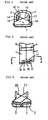
- An enlarged view of the binder with the locking mechanism according to the invention (a) a front elevational view, (b) a plan view and (c) a right side view
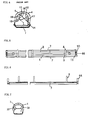
- a view illustrating the first base plate provided with part of the locking mechanism according to the invention (a) a front elevational view, (b) a plan view and (c) a right side view
- a view illustrating the second base plate provided with another part of the locking mechanism according to the invention (a) a front elevational view, (b) a plan view and (c) a right side view
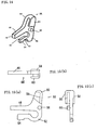
- a view illustrating the structure of the locking member according to the invention (a) a front elevational view, (b) a plan view and (c) a right side view
- the engaging recess of the second actuating member comprises a first surface provided at a location for preventing the movement of the second actuating member, and a second surface on which the engaging projection engages under the influence of the elastic portion, whereby under a condition where the binder rings are closed, the forward end of the engaging projection engages with the first surface to prevent the movement of the first actuating member against an external force in a direction to open the binder rings, and when both the actuating members are pushed in opposite directions, the engaging projection is pivotally moved about the pivoted portion to be disengaged from the engaging recess.
- the engaging projection and the elastic portion extend substantially parallel to each other from the pivoted portion.
- the elastic portion has an arcuate proximal end separated from the engaging projection.
- the locking member for binder rings above described according to the invention is a member integrally comprising a pivoted portion pivotally mounted in the first actuating member, an engaging projection which engages with an engaging recess of the second actuating member to prevent a movement of the second actuating member, an elastic portion abutting against an upper surface of the first base plate to urge the engaging projection to the engaging recess, and a first finger hooking portion provided at a location opposite to the second finger hooking portion.
- the pivoted portion of the locking member is pivotally mounted on a shaft provided on the inner surface of the first actuating member.
- the pivoted portion may be formed by a shaft which may be pivoted in a shaft hole formed in the first actuating member.
- the first and second base plates are elastically moved downwards about their outer edges supported by the elastic sheath, whereby the right and left binder rings abut against each other and they are hence closed, while the engaging projection of the locking member becomes aligned with and below the engaging recess of the first actuating member so as to be fitted in the engaging recess with the aid of the elastic force of the elastic portion, thereby achieving the automatic locking.
- the engaging projection is elastically biased described above, no unlocking occurs even if being subjected to any shock during transportation or the like.
- both the finger hooking portions are pushed in opposite directions, whereby the engaging projection is disengaged from the engaging recess of the second actuating member against the elastic force of the elastic portion. Then, both the finger hooking portions are continuously pushed, whereby the first and second actuating members are pushed in opposite directions, so that both the base plates are upwards pushed to elastically move to upward positions, thereby opening the binder rings. It is very convenient that the locking and unlocking are automatically effected in accordance with the normal opening and closing operations in this manner.
- the engaging recess of the second actuating member comprises a first surface provided at a position for preventing the movement of the second actuating member and a second surface on which the engaging projection engages under the influence of the elastic portion, whereby under a condition that the binder rings are closed, the forward end of the engaging projection engages with the first surface to prevent the movement of the first actuating member against an external force in a direction to open the binder rings, and when both the actuating members are pushed in opposite directions, the engaging projection is pivotally moved about the pivoted portion to be disengaged from the engaging recess.
- the elastic force is applied at right angles to the extending direction of the engaging projection, whereby the required elastic action above described can be obtained.
- the elastic portion has an arcuate proximal end which swells in a direction away from the engaging projection, whereby the portion forming the elastic portion is elongated to distribute exerted stresses over a wide range, resulting in a prolongation of the lifetime of the locking member.
- Figure 5 is a plan view of a loose-leaf binder with a locking member according to the invention.
- Figures 6 and 7 are left and right side views of the loose-leaf binder shown in Figure 5, respectively.
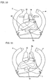
- Figures 8 and 11 are enlarged front elevations of one end of the loose-leaf binder with the locking member under a closed and an opened condition, respectively.
- an elastic sheath 7 is provided which restrains the outer edges and allows the binder rings 3 and 4 to be opened and closed by elastic upward and downward movements of the base plates 1 and 2.
- the downward movements of the base plates 1 and 2 are limited by an abutment of the binder rings 3 and 4 against each other, which is the closed state of the binder rings 3 and 4 as shown in Figure 8(a).
- the upward movements of the base plates 1 and 2 about their outer edges as pivot shafts are limited by a plurality of stopper member 18' and 19 provided alternately on bottom surfaces of the base plates 1 and 2 along inner abutment edges of their bottoms as shown in Figures 11, 12 (a) and 13 (a), which is the opened state of the binder rings 3 and 4.
- the first and second base plates 1 and 2 are provided at both ends with first and second actuating members 10 and 11 fixed thereat by integral formation, respectively, which extend at right angles to longitudinal directions (axial directions) of the first and second base plates 1 and 2 and intersecting each other. Further, the base plates are each formed along the outer edge with a ridge 21 and 22 on which the elastic sheath is fitted and assembled as shown in Figure 8(a).
- a locking mechanism according to the invention will be explained herein with reference to Figures 8 to 15.
- a locking member may be provided only at one end of the binder, or locking members may be provided one at each end of the binder and since they have a similar or symmetrical structure, the locking member at one end only will be explained.
- Figures 8 to 11 illustrate the binder with the locking mechanism according to the invention among which Figures 9 and 10 are views for explaining the consecutive operations of the mechanism.
- Figure 12 illustrates the structure of the one end of the first base plate provided with part of the locking mechanism, and (a) is a front view, (b) a plan view and (c) a right side view, respectively.
- Figure 13 illustrates the structure of the one end of the second base plate provided with another part of the locking mechanism, and (a) is a front view, (b) a plan view and (c) a right side view, respectively.
- Figure 14 is a perspective view of the locking member.
- Figure 15 illustrates the structure of the locking member, and (a) is a front view, (b) a plan view and (c) a right side view, respectively.
- the first actuating member 10 is formed at its upper end with an actuating protrusion 34, and the second actuating member 11 forms at its upper end a finger hooking portion 20.
- the locking member 44 forms a finger hooking portion 58 at upper outside portion.
- the first and second actuating members 10 and 11 are closely arranged to be shifted in the longitudinal direction of the base plates 1 and 2 to form a clearance therebetween in which the locking member 44 is arranged. When the finger hooking portions 20 and 58 are pushed in opposite directions, the second locking member 11 is first unlocked as described later.
- the actuating protrusion 34 is also pushed by the finger hooking portion 58, whereby the first and second base plates 1 and 2 are elastically upwards moved to open the binder rings 3 and 4.
- the base plates 1 and 2 are moved downwards to bind leaves, at which instant the second actuating member 11 is automatically locked.
- the first actuating member 10 is formed with a shaft hole 32 in the proximity of the right hand edge viewed in Figure 12 (a) for receiving the shaft 58 of locking member 44. Further, the first actuating member 10 is provided at its upper end with an actuating protrusion 34 to which a force of the finger is applied through the finger hooking portion 58 of the locking member 44. Adjacent the first actuating member 10, the first base plate 1 is formed with holding surface 36 against which the abutment portion 54 of an elastic portion of the locking member 44 abuts.
- the second actuating member 11 includes an engaging recess 38 having a first surface 40 and a second surface 42.
- the first surface 40 is adapted to anchor the forward end of an engaging projection 46 of the locking member 44 to prevent the binder rings from opening, while the second surface 42 is adapted to contact the side surface of the engaging projection 46 biased by an elastic portion 52 to maintain the locked condition.
- the locking member 44 includes a shaft 56 adapted to be fitted in the shaft hole 32 provided in the first actuating member 10 and is able to pivotally move about the shaft 56.
- the locking member 44 is substantially a plate-shaped member integrally formed of a strong synthetic resin or the like.
- the locking member 44 may be formed with a shaft hole, while the first actuating member 10 may be provided with a corresponding shaft to be fitted in the shaft hole.
- the locking member 44 integrally includes the engaging projection 46 adapted to anchor the first surface 40 of the engaging recess 38 of the second actuating member 11 to prevent its movement, the elastic portion 52 having the abutment portion 54 adapted to abut against the holding surface 36 provided on the upper surface of the first actuating member 10 of the first base plate 1 to urge the engaging projection 46 to the engaging recess 38, and the first finger hooking portion 58 located at a position opposite to the second finger hooking portion 20.
- the locking member 44 may be provided at the finger hooking portion 58 with a cover portion 60 for covering the actuating protrusion 34 provided on the first actuating member 10. Between an inner wall 59 of the cover portion 60 and the actuating protrusion 34 (its edge on the right side viewed in Figure 8 (a)), a clearance 62 is provided, and the finger hooking portions 20 and 58 are pushed in opposite directions to disengage the engaging projection 46 from the engaging recess 38, whereby the inner wall of the cover portion 60 engages with the actuating protrusion 34 to transmit the movement of the finger hooking portion 58 to the first actuating member 10, thereby opening the binder rings. Without using the above procedure, such an unlocking is also possible.
- the elastic portion 52 of the locking member 44 may be deformed to an excessive extent, resulting in a reduction in effective service life.
- An undesirable force unintentionally opening the binder rings arising from the binder or the like may be applied to the engaging end 48 of the engaging projection 46 through the engaging recess 38 of the second actuating member 11.
- the force applied to the engaging projection 46 acts substantially at right angles to the fixed shaft 56, so that the second actuating member 11 cannot be moved and hence the locking is maintained.
- the upper surface of the forward end of the engaging projection 46 is always urged upwards by the elastic portion 52 to be brought into contact with the opposite wall surface of the engaging recess 38.
- the engaging projection 46 and the elastic portion 52 are arranged substantially parallel to each other, interposing a slot 50 therebetween.
- the elastic portion 52 is provided with an arcuate proximal end 53 having a large radius of curvature.
- the locking on closing the binder rings from the open state to the closed state the locking is automatically effected to preclude the opening of the binder rings due to an undesirable external force acting upon the binder rings, while when the finger hooking portions are actuated to open the binder rings, the locking can be readily unlocked to open the binder rings with ease.
Landscapes
- Sheet Holders (AREA)
- Clamps And Clips (AREA)
Applications Claiming Priority (2)
| Application Number | Priority Date | Filing Date | Title |
|---|---|---|---|
| JP2003387673A JP4472968B2 (ja) | 2003-11-18 | 2003-11-18 | ロック付きルースリーフ綴具 |
| JP2003387673 | 2003-11-18 |
Publications (1)
| Publication Number | Publication Date |
|---|---|
| EP1533136A1 true EP1533136A1 (en) | 2005-05-25 |
Family
ID=34431538
Family Applications (1)
| Application Number | Title | Priority Date | Filing Date |
|---|---|---|---|
| EP04291884A Withdrawn EP1533136A1 (en) | 2003-11-18 | 2004-07-23 | Loose-leaf binder with locking mechanism |
Country Status (4)
| Country | Link |
|---|---|
| US (1) | US7134800B2 (ja) |
| EP (1) | EP1533136A1 (ja) |
| JP (1) | JP4472968B2 (ja) |
| CN (1) | CN100446994C (ja) |
Cited By (1)
| Publication number | Priority date | Publication date | Assignee | Title |
|---|---|---|---|---|
| CN101495323B (zh) * | 2006-07-25 | 2010-12-29 | 株式会社喜利 | 文件夹用装订件 |
Families Citing this family (8)
| Publication number | Priority date | Publication date | Assignee | Title |
|---|---|---|---|---|
| US7524127B2 (en) | 2005-12-12 | 2009-04-28 | Staples The Office Superstore, Llc | Ring binder mechanism |
| US7527449B2 (en) | 2005-12-12 | 2009-05-05 | Staples The Office Superstore, Llc | Ring binder mechanism |
| US7399136B2 (en) | 2006-01-06 | 2008-07-15 | Staples The Office Superstore Llc | Molded binder |
| US10086639B2 (en) | 2013-03-15 | 2018-10-02 | Hans Johann Horn | Binder apparatus |
| CN104108258B (zh) * | 2013-04-16 | 2017-07-18 | 国誉株式会社 | 装订用具以及文件夹 |
| JP5805148B2 (ja) * | 2013-07-08 | 2015-11-04 | 株式会社カネダ技研 | ルーズリーフ綴じ具 |
| KR102774877B1 (ko) * | 2023-10-18 | 2025-02-27 | 카네다 컴퍼니 리미티드 | 링식 제본구 |
| JP7402583B1 (ja) * | 2023-10-18 | 2023-12-21 | 株式会社カネダ技研 | リング式綴じ具 |
Citations (4)
| Publication number | Priority date | Publication date | Assignee | Title |
|---|---|---|---|---|
| US2183231A (en) * | 1938-11-16 | 1939-12-12 | Trussell Mfg Co | Loose-leaf binder |
| US3205894A (en) * | 1957-05-08 | 1965-09-14 | Brock And Rankin Inc | Floating ring loose-leaf binder |
| US3348550A (en) * | 1966-01-06 | 1967-10-24 | Feldco Major Inc | Ring binder |
| US3827111A (en) * | 1971-12-28 | 1974-08-06 | Connell J O | Fastening means for detachably securing together mating ends of a binder ring construction and the like |
Family Cites Families (13)
| Publication number | Priority date | Publication date | Assignee | Title |
|---|---|---|---|---|
| US1800268A (en) * | 1927-06-16 | 1931-04-14 | Trussell Mfg Co | Loose-leaf binder |
| US2381040A (en) * | 1943-09-02 | 1945-08-07 | Wilson Jones Co | Loose-leaf binder |
| US2871863A (en) * | 1956-09-24 | 1959-02-03 | Wilson Jones Co | Opening and closing levers for ring binders |
| FR1213489A (fr) * | 1959-07-08 | 1960-04-01 | Dispositif relieur à feuillets mobiles | |
| US3205896A (en) * | 1962-10-18 | 1965-09-14 | Weichert Willi Fritz Carl | Mechanism for a loose-leaf book |
| US3253603A (en) * | 1963-09-16 | 1966-05-31 | Gen Binding Corp | Binding element |
| JPH0592687A (ja) * | 1991-06-03 | 1993-04-16 | Katsumi Kaneda | バインダー綴具のロツク装置 |
| JPH0799480B2 (ja) | 1991-09-25 | 1995-10-25 | 株式会社三社電機製作所 | 複層消音材 |
| US5346325A (en) * | 1992-07-24 | 1994-09-13 | Seiichi Yamanoi | Paper holder having a locking device |
| JP2563056B2 (ja) * | 1992-09-09 | 1996-12-11 | 克己 金田 | 開閉機構を有するバインダー綴具 |
| JP2000118182A (ja) * | 1998-10-19 | 2000-04-25 | Katsumi Kaneda | ロック付きルースリーフ綴具 |
| JP2000211282A (ja) * | 1999-01-26 | 2000-08-02 | Kaneda Giken:Kk | ロック付きル―スリ―フ綴具 |
| JP2001239781A (ja) * | 2000-02-25 | 2001-09-04 | Onishi Shoko Kk | バインダー綴具の製法 |
-
2003
- 2003-11-18 JP JP2003387673A patent/JP4472968B2/ja not_active Expired - Lifetime
-
2004
- 2004-03-18 US US10/803,423 patent/US7134800B2/en not_active Expired - Fee Related
- 2004-04-13 CN CNB2004100346364A patent/CN100446994C/zh not_active Expired - Fee Related
- 2004-07-23 EP EP04291884A patent/EP1533136A1/en not_active Withdrawn
Patent Citations (4)
| Publication number | Priority date | Publication date | Assignee | Title |
|---|---|---|---|---|
| US2183231A (en) * | 1938-11-16 | 1939-12-12 | Trussell Mfg Co | Loose-leaf binder |
| US3205894A (en) * | 1957-05-08 | 1965-09-14 | Brock And Rankin Inc | Floating ring loose-leaf binder |
| US3348550A (en) * | 1966-01-06 | 1967-10-24 | Feldco Major Inc | Ring binder |
| US3827111A (en) * | 1971-12-28 | 1974-08-06 | Connell J O | Fastening means for detachably securing together mating ends of a binder ring construction and the like |
Cited By (1)
| Publication number | Priority date | Publication date | Assignee | Title |
|---|---|---|---|---|
| CN101495323B (zh) * | 2006-07-25 | 2010-12-29 | 株式会社喜利 | 文件夹用装订件 |
Also Published As
| Publication number | Publication date |
|---|---|
| JP2005144928A (ja) | 2005-06-09 |
| US7134800B2 (en) | 2006-11-14 |
| CN1618628A (zh) | 2005-05-25 |
| CN100446994C (zh) | 2008-12-31 |
| US20050105958A1 (en) | 2005-05-19 |
| JP4472968B2 (ja) | 2010-06-02 |
Similar Documents
| Publication | Publication Date | Title |
|---|---|---|
| US3884586A (en) | Safety lock loose-leaf ring binder mechanism | |
| CA1317845C (en) | Trigger mechanism for ring binder | |
| US7661898B2 (en) | Soft close ring binder mechanism with reinforced travel bar | |
| CN100537294C (zh) | 车辆的滑轨结构 | |
| US4919557A (en) | Looseleaf binder with sliding lock mechanism | |
| US7134800B2 (en) | Loose-leaf binder with lock | |
| US5180247A (en) | Ring binder | |
| EP0657305A1 (en) | Paper holder having a locking device | |
| US9091101B2 (en) | Vehicle liftgate striker and latch construction | |
| US6314624B1 (en) | Slide of auto-lock zipper | |
| US20060162138A1 (en) | Hanger for rope or the like | |
| US10662680B2 (en) | Door locking device and method for preventing door from opening during side collision | |
| JPS6220076B2 (ja) | ||
| US7051410B2 (en) | Snap hook with two opposed closing figures | |
| US7270496B2 (en) | Ring mechanism for a ring binder | |
| EP1045186A2 (en) | Hose clip | |
| US6343678B1 (en) | Brake hold down assembly | |
| HK1075871A (en) | Loose-leaf binder with locking mechanism | |
| US7487879B2 (en) | Fuel filler cap | |
| KR100878635B1 (ko) | 어느 하나가 다른 하나의 상부에 적층된 두 개의 컨테이너를 결합하기 위한 결합부재 | |
| JP7297387B2 (ja) | ロック構造 | |
| CA2500817A1 (en) | Soft close ring binder mechanism with reinforced travel bar | |
| KR100501240B1 (ko) | 자동차용 도어아웃사이드핸들의 핸들이탈방지구조 | |
| CA2056942C (en) | Ring binder | |
| US6438806B1 (en) | Slide structure for zipper |
Legal Events
| Date | Code | Title | Description |
|---|---|---|---|
| PUAI | Public reference made under article 153(3) epc to a published international application that has entered the european phase |
Free format text: ORIGINAL CODE: 0009012 |
|
| AK | Designated contracting states |
Kind code of ref document: A1 Designated state(s): AT BE BG CH CY CZ DE DK EE ES FI FR GB GR HU IE IT LI LU MC NL PL PT RO SE SI SK TR |
|
| AX | Request for extension of the european patent |
Extension state: AL HR LT LV MK |
|
| REG | Reference to a national code |
Ref country code: HK Ref legal event code: DE Ref document number: 1075871 Country of ref document: HK |
|
| 17P | Request for examination filed |
Effective date: 20051125 |
|
| AKX | Designation fees paid |
Designated state(s): DE FR GB IT |
|
| 17Q | First examination report despatched |
Effective date: 20070726 |
|
| GRAP | Despatch of communication of intention to grant a patent |
Free format text: ORIGINAL CODE: EPIDOSNIGR1 |
|
| STAA | Information on the status of an ep patent application or granted ep patent |
Free format text: STATUS: THE APPLICATION IS DEEMED TO BE WITHDRAWN |
|
| 18D | Application deemed to be withdrawn |
Effective date: 20090929 |
|
| REG | Reference to a national code |
Ref country code: HK Ref legal event code: WD Ref document number: 1075871 Country of ref document: HK |