EP1533129B1 - Dispositif de chauffage de substrat - Google Patents
Dispositif de chauffage de substrat Download PDFInfo
- Publication number
- EP1533129B1 EP1533129B1 EP04256904A EP04256904A EP1533129B1 EP 1533129 B1 EP1533129 B1 EP 1533129B1 EP 04256904 A EP04256904 A EP 04256904A EP 04256904 A EP04256904 A EP 04256904A EP 1533129 B1 EP1533129 B1 EP 1533129B1
- Authority
- EP
- European Patent Office
- Prior art keywords
- substrate
- heating assembly
- heating
- image
- producing machine
- Prior art date
- Legal status (The legal status is an assumption and is not a legal conclusion. Google has not performed a legal analysis and makes no representation as to the accuracy of the status listed.)
- Expired - Lifetime
Links
- 239000000758 substrate Substances 0.000 title claims description 171
- 238000010438 heat treatment Methods 0.000 title claims description 93
- 238000003384 imaging method Methods 0.000 claims description 12
- 238000011144 upstream manufacturing Methods 0.000 claims description 12
- 239000000976 ink Substances 0.000 description 41
- 239000012071 phase Substances 0.000 description 25
- 239000007787 solid Substances 0.000 description 7
- 230000000712 assembly Effects 0.000 description 6
- 238000000429 assembly Methods 0.000 description 6
- 239000007788 liquid Substances 0.000 description 3
- 239000007791 liquid phase Substances 0.000 description 3
- 238000000034 method Methods 0.000 description 3
- XAGFODPZIPBFFR-UHFFFAOYSA-N aluminium Chemical compound [Al] XAGFODPZIPBFFR-UHFFFAOYSA-N 0.000 description 2
- 229910052782 aluminium Inorganic materials 0.000 description 2
- 238000002844 melting Methods 0.000 description 2
- 230000008018 melting Effects 0.000 description 2
- 230000015572 biosynthetic process Effects 0.000 description 1
- 239000003086 colorant Substances 0.000 description 1
- 239000007790 solid phase Substances 0.000 description 1
Images

Classifications
-
- B—PERFORMING OPERATIONS; TRANSPORTING
- B41—PRINTING; LINING MACHINES; TYPEWRITERS; STAMPS
- B41J—TYPEWRITERS; SELECTIVE PRINTING MECHANISMS, i.e. MECHANISMS PRINTING OTHERWISE THAN FROM A FORME; CORRECTION OF TYPOGRAPHICAL ERRORS
- B41J11/00—Devices or arrangements of selective printing mechanisms, e.g. ink-jet printers or thermal printers, for supporting or handling copy material in sheet or web form
- B41J11/0015—Devices or arrangements of selective printing mechanisms, e.g. ink-jet printers or thermal printers, for supporting or handling copy material in sheet or web form for treating before, during or after printing or for uniform coating or laminating the copy material before or after printing
- B41J11/002—Curing or drying the ink on the copy materials, e.g. by heating or irradiating
- B41J11/0024—Curing or drying the ink on the copy materials, e.g. by heating or irradiating using conduction means, e.g. by using a heated platen
Definitions
- This invention relates generally to image producing machines, and more particularly to such a machine having a plurality of image pre-transfer substrate heating assemblies. Such assemblies are particularly useful in a high-speed phase change ink image producing machine or printer.
- phase change ink image producing machines or printers employ phase change inks that are in the solid phase at ambient temperature, but exist in the molten or melted liquid phase (and can be ejected as drops or jets) at the elevated operating temperature of the machine or printer.
- droplets or jets of the molten or liquid phase change ink are ejected from a printhead device of the printer onto a printing media.
- Such ejection can be directly onto a final image receiving substrate, or indirectly onto an imaging member before transfer from it to the final image receiving media.
- the ink droplets contact the surface of the printing media, they quickly solidify to create an image in the form of a predetermined pattern of solidified ink drops.
- phase change ink printing process includes raising the temperature of a solid form of the phase change ink so as to melt it and form a molten liquid phase change ink. It also includes applying droplets of the phase change ink in a liquid form onto an imaging surface in a pattern using a device such as an ink jet printhead. The process then includes solidifying the phase change ink droplets on the imaging surface, transferring them the image receiving substrate, and fixing the phase change ink to the substrate.
- an ink image producing machine that has (a) imaging devices, including at least one ink jet print head and an image receiving station for producing an ink image on a heated substrate; (b) a substrate handling assembly including holding devices for holding supplies of substrates, and transport feeding devices for transporting and feeding substrates in a substrate direction towards the image receiving station; (c) a first substrate heating assembly located upstream of the image receiving station for initially heating each substrate being fed and transported from the holding devices; and (d) a second substrate heating assembly located downstream of the first substrate heating assembly and upstream of said image receiving station, relative to the substrate feeding direction, for controllably re-heating each substrate, initially heated by the first substrate heating assembly, to a desired ink image receiving temperature, [see claim 1]
- the machine 10 includes a frame 11 to which are mounted directly or indirectly all the operating subsystems and components thereof as will be described below.
- the high-speed phase change ink image producing machine or printer 10 includes an imaging member 12 that is shown in the form of a drum, but can equally be in the form of a supported endless belt.
- the imaging member 12 has an imaging surface 14 that is movable in the direction 16, and on which phase change ink images are formed.
- the high-speed phase change ink image producing machine or printer 10 also includes a phase change ink delivery subsystem 20 that has at least one source 22 of one color phase change ink in solid form. Since the phase change ink image producing machine or printer 10 is a multicolor image producing machine, the ink delivery system 20 includes four (4) sources 22, 24, 26, 28, representing four (4) different colors CYMK (cyan, yellow, magenta, black) of phase change inks.
- the phase change ink delivery system also includes melting and control apparatus (not shown in FIG. 1 ) for melting or phase changing the solid form of the phase change ink into a liquid 20 form, and then supplying the liquid form to a printhead system 30 including at least one printhead assembly 32. Since the phase change ink image producing machine or printer 10 is a high-speed, or high throughput, multicolor image producing machine, the printhead system includes four (4) separate printhead assemblies 32, 34, 36 and 38 as shown.
- the phase change ink image producing machine or printer 10 includes a substrate supply and handling system 40.
- the substrate supply and handling system 40 for example may include substrate supply sources 42, 44, 46, 48, of which supply source 48 for example is a high capacity paper supply or feeder for storing and supplying image receiving substrates in the form of cut sheets for example.
- the substrate supply and handling system 40 in any case includes a substrate handling system 50 that has the multi-stage substrate pre-heater assembly 100 of the present invention (to be described in detail below).
- the substrate handling system 50 may also includes a post-transfer, pre-fuser substrate and image heater 54, and a fusing device 60.
- the phase change ink image producing machine or printer 10 as shown may also include an original document feeder 70 that has a document holding tray 72, document sheet feeding and retrieval devices 74, and a document exposure and scanning system 76.
- the ESS or controller 80 for example is a self-contained, dedicated mini-computer having a central processor unit (CPU) 82, electronic storage 84, and a display or user interface (UI) 86.
- the ESS or controller 80 for example includes sensor input and control means 88 as well as a pixel placement and control means 89.
- the CPU 82 reads, captures, prepares and manages the image data flow between image input sources such as the scanning system 76, or an online or a work station connection 90, and the printhead assemblies 32, 34, 36, 38.
- the ESS or controller 80 is the main multi-tasking processor for operating and controlling all of the other machine subsystems and functions, including the machine's printing operations.
- image data for an image to be produced is sent to the controller 80 from either the scanning system 76 or via the online or work station connection 90 for processing and output to the printhead assemblies 32, 34, 36, 38. Additionally, the controller determines and/or accepts related subsystem and component controls, for example from operator inputs via the user interface 86, and accordingly executes such controls.
- pixel placement control is exercised relative to the imaging surface 14 forming a desired image per such image data
- a receiving substrates is supplied by anyone of the sources 42, 44, 46, 48 and handled by means 50 in timed registration with image formation on the surface 14, and the image is transferred within the transfer nip or station 92, from the surface 14 onto the receiving substrate for subsequent fusing at fusing device 60.
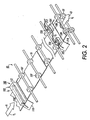
- the substrate handling system 50 includes the multi-stage substrate pre-transfer substrate assembly 100 of the present invention.
- the multi-stage substrate pre-transfer substrate assembly 100 as further illustrated in greater detail, includes a first substrate heating assembly 102 and a second substrate heating assembly 104, 105.
- the substrate handling system 50 includes substrate path guide baffles (not shown) located at the entrance and exit sides respectively of the multi-stage pre-transfer substrate heating assembly 100 of the present invention.
- the first substrate heating assembly 102 is located near the start of the substrate feeding path 40.
- the first substrate heating assembly 102 is a full-width device spanning the entire width of the substrate feeding path 40, and may for example include a plate-on-plate heater as shown defining a part of the substrate path 40 between two plates 110, 112.
- the plates 110, 112 may be thermally conductive, and as such can be heated aluminum blocks that heat the substrate SS as the substrate comes into contact with them.
- this first substrate heating assembly 102 could include a' belt-on-belt heater as described for example in U.S. patent Application Serial No. 10/320,821 .
- the first substrate heating assembly 102 as such includes a continuous, full-width heating element 106 having a first length L1 equal to at least a width of each substrate SS, or extending across the substrate path 40 for heating an entire edge to edge width of each substrate SS as it is moved through the first substrate heating assembly 102.
- the substrate handling system 50 in one embodiment is controlled to move the substrate through the first substrate heating assembly 102 at a first relatively slow speed V1 (e.g. a speed of a few hundred mm/sec), in order to provide sufficient dwell time in the heating assembly to fully heat the substrate to a first desired temperature, for example, of at least about 37°C.
- V1 relatively slow speed
- the substrate handling system 50 then accelerates the substrate from the first substrate heating assembly to a second and relatively higher desired speed V2 (approximately 1440 mm/sec) needed for matching the speeds of other components within the image receiving nip or transfer station 92.
- the second substrate heating assembly 104, 105 is located downstream of the first substrate heating assembly 102 and upstream of the image receiving or transfer station 92, relative to the substrate feeding direction 41, 43, for controllably re-heating each substrate, initially heated by the first substrate heating assembly 102, and to a desired image receiving temperature Td.
- the second substrate heating assembly 104 may also include a plate-on-plate heater assembly defining part of the substrate path 40 between two plates 210, 212.
- the plates 210, 212 may be thermally conductive, and as such can be heated aluminum blocks that heat the substrate as the substrate comes into contact with them.
- the second substrate heating assembly 104 immediately preceding a substrate registration assembly 51 ensures that the substrate is at the proper temperature (generally about 37° degrees) for effective image transfer.
- the second substrate heating assembly 104 equally may be located downstream or after the substrate registration assembly 51.
- the second substrate' heating assembly 104 as such is necessary because the substrate would have likely cooled off, due for example to contact with unheated elements such as feed rollers 107 in the substrate path 40, following its heating by the upstream first substrate heating assembly 102.
- the second substrate heating assembly 104 includes at least one heating device 104, 105 each having a second length L2 that is less than a width of each substrate, and extends across only a portion of the path 40, for heating only a part of an edge to edge width of each substrate as it is moved through the second substrate heating assembly 104, 105.
- the second substrate heating assembly 104, 105 includes only partial width heating elements 108, 109 positioned to reheat such areas of the substrate that would have come into contact with such feed rollers 107.
- the second substrate heating assembly 104, 105 thus includes the two heating elements 108, 109 that are spaced from one another in a cross direction to the path 40.
- the second substrate heating assembly 104, 105 can be smaller, and the substrate transport speed 43 thereover can be relatively higher.
- the first or upstream substrate heating assembly 102 located near the substrate supply source 44, 48 performs the primary substrate heating as the substrate passes through it at a relatively slow speed. Each substrate so heated is then accelerated to a relatively higher and desired image transfer speed across the second substrate heating assembly 104 and across the substrate registration assembly 51, and all prior to image transfer.
- the second substrate heating assembly is located immediately preceding or upstream of the registration assembly 51 (as shown) or after the registration assembly 51, for providing final and adjustment heating in order to enable effective image transfer.
- the second substrate heating assembly can thus be small, and may cover only portions of the width of the substrate path as shown.
- the second substrate heating assembly 104 also includes temperature sensing and control means 220 connected to the machine controller or ESS 80 and to each heating element 108, 109 for sensing a temperature of the substrate SS and controlling that of the heating elements 108, 109 of the second substrate heating assembly 104, 105.
- the substrate handling assembly or system 50 includes speed control means connected to the controller 80 and feed rollers 107 for moving each substrate being fed at the first speed V1 through the first substrate heating assembly 102, and at a second and different speed V2 through the second substrate heating assembly 104.
- the first speed V1 could be calculated and controlled as a function of a predetermined dwell time for each substrate moving through the first substrate heating assembly 102.
- the second and different speed V2 can be calculated and controlled as a function of a difference between an actual temperature Ta of the each substrate coming from the first substrate heating assembly 102 and a predetermined desired image receiving temperature Td.
- an ink image producing machine that has (a) imaging devices, including at least one ink jet print head and an image receiving station for producing an ink image on a heated substrate; (b) a substrate handling assembly including holding devices for holding supplies of substrates, and transport feeding devices for transporting and feeding substrates in a substrate direction towards the image receiving station; (c) a first substrate heating assembly located upstream of the image receiving station for initially heating each substrate being fed and transported from the holding devices; and (d) a second substrate heating assembly located downstream of the first substrate heating assembly and upstream of said image receiving station, relative to the substrate feeding direction, for controllably re-heating each substrate, initially heated by the first substrate heating assembly, to a desired ink image receiving temperature.
Landscapes
- Ink Jet (AREA)
- Accessory Devices And Overall Control Thereof (AREA)
Claims (9)
- Machine de production d'image à encre comprenant:(a) un moyen de formation d'image, incluant au moins une tête d'impression à jet d'encre et une station de réception d'image pour produire une image à encre sur un substrat chauffé;(b) un ensemble de manipulation de substrat incluant un moyen de maintien pour maintenir une alimentation de substrats, et un moyen de transport et d'alimentation pour transporter et alimenter des substrats dans une direction de substrat vers ladite station de réception d'image;(c) un premier ensemble de chauffage de substrat situé en amont de ladite station de réception d'image pour le chauffage initial de chaque substrat qui est alimenté et transporté dudit moyen de maintien; et(d) un deuxième ensemble de chauffage de substrat situé en aval dudit premier ensemble de chauffage de substrat et en amont de ladite station de réception d'image, par rapport à ladite direction d'alimentation de substrat, pour chauffer à nouveau de manière commandée ledit chaque substrat, chauffé initialement par ledit premier ensemble de chauffage de substrat, à une température de réception d'image à encre désirée,dans laquelle ledit ensemble de manipulation de substrat inclut un moyen de commande de vitesse pour déplacer ledit chaque substrat, en cours d'alimentation, à une première vitesse à travers ledit premier ensemble de chauffage et à une deuxième vitesse, distincte, à travers ledit deuxième ensemble de chauffage.
- Machine de production d'image à encre selon la revendication 1, dans laquelle ledit moyen de formation d'image inclut un élément de formation d'image intermédiaire destiné à soutenir et à transférer temporairement ladite image à encre sur le substrat chauffé de ladite station de réception d'image.
- Machine de production d'image à encre selon la revendication 1 ou la revendication 2, dans laquelle ladite deuxième vitesse distincte est relativement plus élevée que ladite première vitesse.
- Machine de production d'image à encre de l'une quelconque des revendications précédentes, dans laquelle ladite première vitesse est calculée et commandée comme une fonction d'un temps de séjour prédéterminé pour ledit chaque substrat à travers ledit premier ensemble de chauffage de substrat; et, dans laquelle ladite deuxième vitesse distincte est calculée et commandée comme une fonction d'une différence entre une température effective dudit chaque substrat provenant dudit premier ensemble de chauffage et une température de réception d'image prédéterminée.
- Machine de production d'image à encre selon l'une quelconque des revendications précédentes, dans laquelle ledit premier ensemble de chauffage de substrat inclut un élément de chauffage continu sur toute la largeur ayant une première longueur égale à une largeur dudit chaque substrat, ladite première longueur s'étendant à travers un chemin de mouvement dudit chaque substrat pour chauffer toute une largeur d'un bord à l'autre dudit chaque substrat à mesure que celui-ci se déplace à travers ledit premier ensemble de chauffage.
- Machine de production d'image à encre selon l'une quelconque des revendications précédentes, dans laquelle ledit deuxième ensemble de chauffage de substrat inclut au moins un élément de chauffage ayant une deuxième longueur inférieure à une largeur dudit chaque substrat, ladite deuxième longueur s'étendant à travers une portion seulement d'un chemin de mouvement dudit chaque substrat pour chauffer uniquement une partie d'une largeur d'un bord à l'autre dudit chaque substrat à mesure que celui-ci se déplace à travers ledit deuxième ensemble de chauffage.
- Machine de production d'image à encre selon la revendication 6, dans laquelle ledit deuxième ensemble de chauffage inclut deux desdits au moins un élément de chauffage écartés l'un par rapport à l'autre dans une direction transverse audit chemin de mouvement de substrat.
- Machine de production d'image à encre de la revendication 1, dans laquelle ledit deuxième ensemble de chauffage de substrat inclut un moyen de détection et de commande de température connecté audit au moins un élément de chauffage pour détecter une température de chaque substrat et commander une température dudit deuxième ensemble de chauffage de substrat.
- Machine de production d'image comprenant un ensemble de chauffage de substrat avant transfert multi-étagé pour chauffer un substrat et régler une température d'un tel substrat avant un transfert d'image, l'ensemble de chauffage de substrat avant transfert multi-étagé comprenant:(a) un premier ensemble de chauffage de substrat situé en amont d'une station de transfert et de réception d'image dans la machine pour le chauffage initial de chaque substrat qui est alimenté à ladite station de transfert et de réception d'image; et(b) un deuxième ensemble de chauffage de substrat situé en aval dudit premier ensemble de chauffage de substrat et en amont de ladite station de transfert et de réception d'image par rapport à une direction d'alimentation de substrat, pour chauffer de nouveau de manière commandée ledit chaque substrat, chauffé initialement par ledit premier ensemble de chauffage de substrat, à une température de réception d'image désirée.
Applications Claiming Priority (2)
| Application Number | Priority Date | Filing Date | Title |
|---|---|---|---|
| US10/719,398 US6932526B2 (en) | 2003-11-21 | 2003-11-21 | Multi-stage pre-transfer substrate heating assembly |
| US719398 | 2003-11-21 |
Publications (2)
| Publication Number | Publication Date |
|---|---|
| EP1533129A1 EP1533129A1 (fr) | 2005-05-25 |
| EP1533129B1 true EP1533129B1 (fr) | 2008-07-30 |
Family
ID=34435808
Family Applications (1)
| Application Number | Title | Priority Date | Filing Date |
|---|---|---|---|
| EP04256904A Expired - Lifetime EP1533129B1 (fr) | 2003-11-21 | 2004-11-08 | Dispositif de chauffage de substrat |
Country Status (7)
| Country | Link |
|---|---|
| US (1) | US6932526B2 (fr) |
| EP (1) | EP1533129B1 (fr) |
| JP (1) | JP4606134B2 (fr) |
| CN (1) | CN100584628C (fr) |
| BR (1) | BRPI0405112A (fr) |
| CA (1) | CA2487506C (fr) |
| DE (1) | DE602004015391D1 (fr) |
Families Citing this family (9)
| Publication number | Priority date | Publication date | Assignee | Title |
|---|---|---|---|---|
| US7866262B2 (en) * | 2006-07-21 | 2011-01-11 | Xerox Corporation | Image responsive pivoting pressure roll |
| US20080204535A1 (en) * | 2007-02-22 | 2008-08-28 | Seiko Epson Corporation | Ink jet printer |
| US7828423B2 (en) | 2007-07-05 | 2010-11-09 | Xerox Corporation | Ink-jet printer using phase-change ink printing on a continuous web |
| US8192005B2 (en) * | 2009-07-29 | 2012-06-05 | Xerox Corporation | Rollers for phase-change ink printing |
| US8668318B2 (en) | 2012-07-26 | 2014-03-11 | Xerox Corporation | System and method for spreading ink on a media web |
| JP6142789B2 (ja) * | 2013-12-10 | 2017-06-07 | セイコーエプソン株式会社 | 記録装置 |
| JP6319556B2 (ja) * | 2014-01-17 | 2018-05-09 | セイコーエプソン株式会社 | 液体吐出装置 |
| DE102018205254A1 (de) * | 2017-05-11 | 2018-11-15 | Heidelberger Druckmaschinen Ag | Digitaldruckmaschine mit einer Temperiereinrichtung für Bogen |
| JP6973011B2 (ja) * | 2017-12-14 | 2021-11-24 | コニカミノルタ株式会社 | インクジェット記録装置 |
Family Cites Families (11)
| Publication number | Priority date | Publication date | Assignee | Title |
|---|---|---|---|---|
| US4395036A (en) * | 1979-04-26 | 1983-07-26 | Standard Duplicating Machines Corporation | Sheet feeder with stack-holding tray having flexible-band-coupled guide elements |
| JP3115657B2 (ja) * | 1991-10-18 | 2000-12-11 | キヤノン株式会社 | インクジェットプリント装置 |
| US5372852A (en) * | 1992-11-25 | 1994-12-13 | Tektronix, Inc. | Indirect printing process for applying selective phase change ink compositions to substrates |
| US5742315A (en) * | 1995-09-05 | 1998-04-21 | Xerox Corporation | Segmented flexible heater for drying a printed image |
| US6428158B1 (en) * | 1997-11-05 | 2002-08-06 | Xerox Corporation | Liquid ink printer having a heat and hold drier |
| JP2000296607A (ja) * | 1999-04-16 | 2000-10-24 | Mutoh Ind Ltd | インクジェットプリンタ |
| DE10056703C2 (de) * | 2000-11-15 | 2002-11-21 | Technoplot Cad Vertriebs Gmbh | Tintenstrahldrucker mit einem Piezo-Druckkopf zum Ausstoßen von Lactat-Tinte auf ein unbeschichtetes Druckmedium |
| JP2002337331A (ja) * | 2001-05-21 | 2002-11-27 | Isetoo:Kk | インクジェットプリンタにおける乾燥装置 |
| US6639527B2 (en) * | 2001-11-19 | 2003-10-28 | Hewlett-Packard Development Company, L.P. | Inkjet printing system with an intermediate transfer member between the print engine and print medium |
| JP2004136453A (ja) * | 2002-10-15 | 2004-05-13 | Seiko Epson Corp | 記録装置、記録方法、プログラム及びコンピュータシステム |
| JP2004136579A (ja) * | 2002-10-18 | 2004-05-13 | Konica Minolta Holdings Inc | インクジェットプリンタ及びそれを用いたインクジェット画像形成方法 |
-
2003
- 2003-11-21 US US10/719,398 patent/US6932526B2/en not_active Expired - Fee Related
-
2004
- 2004-11-08 DE DE602004015391T patent/DE602004015391D1/de not_active Expired - Lifetime
- 2004-11-08 EP EP04256904A patent/EP1533129B1/fr not_active Expired - Lifetime
- 2004-11-15 CA CA002487506A patent/CA2487506C/fr not_active Expired - Fee Related
- 2004-11-18 BR BR0405112-2A patent/BRPI0405112A/pt not_active IP Right Cessation
- 2004-11-19 JP JP2004336075A patent/JP4606134B2/ja not_active Expired - Fee Related
- 2004-11-22 CN CN200410095019A patent/CN100584628C/zh not_active Expired - Fee Related
Also Published As
| Publication number | Publication date |
|---|---|
| CA2487506A1 (fr) | 2005-05-21 |
| JP4606134B2 (ja) | 2011-01-05 |
| JP2005153526A (ja) | 2005-06-16 |
| US20050111896A1 (en) | 2005-05-26 |
| BRPI0405112A (pt) | 2005-07-19 |
| DE602004015391D1 (de) | 2008-09-11 |
| EP1533129A1 (fr) | 2005-05-25 |
| CN100584628C (zh) | 2010-01-27 |
| US6932526B2 (en) | 2005-08-23 |
| CN1618607A (zh) | 2005-05-25 |
| CA2487506C (fr) | 2008-09-09 |
Similar Documents
| Publication | Publication Date | Title |
|---|---|---|
| US6866375B2 (en) | Solid phase change ink melter assembly and phase change ink image producing machine having same | |
| JPH05134824A (ja) | テキストおよびカラー画像プリンタ | |
| US6746113B1 (en) | Solid phase change ink pre-melter assembly and a phase change ink image producing machine having same | |
| EP1795361A1 (fr) | Assemblage chauffant pour feuilles comportant des plaquettes à palier à air | |
| EP1533129B1 (fr) | Dispositif de chauffage de substrat | |
| KR101875965B1 (ko) | 인쇄기 | |
| US8967789B2 (en) | Spreader/transfix system for handling tabbed media sheets during duplex printing in an inkjet printer | |
| US6764160B1 (en) | Printhead interposing maintenance apparatus and method and image producing machine having same | |
| US6783221B2 (en) | Phase change waste ink control apparatus and method | |
| EP1666269B1 (fr) | Procédé et appareil de montage d'une tête d'impression à jet d'encre | |
| JP2001212948A (ja) | インクジェットプリンタおよびこれに用いる記録媒体 | |
| KR101959573B1 (ko) | 인쇄기 | |
| EP2177361B1 (fr) | Système de pliable à chaud pour dispositif d'imagerie d'encre à changement de phase | |
| US7014897B2 (en) | Imaging member having a textured imaging surface and a phase change ink image producing machine having same | |
| US7347527B2 (en) | System and method for maintaining solid ink printheads | |
| US6948806B2 (en) | Polyimide film substrate pre-heater assembly and a phase change ink imaging machine including same | |
| US6840615B2 (en) | Imaging surface field reconditioning method and apparatus | |
| US8721019B2 (en) | Apparatus and method for treatment of printed ink images | |
| KR101749769B1 (ko) | 상 변화 잉크 화상 형성 장치 | |
| US7648231B2 (en) | System and method for insulating solid ink printheads |
Legal Events
| Date | Code | Title | Description |
|---|---|---|---|
| PUAI | Public reference made under article 153(3) epc to a published international application that has entered the european phase |
Free format text: ORIGINAL CODE: 0009012 |
|
| AK | Designated contracting states |
Kind code of ref document: A1 Designated state(s): AT BE BG CH CY CZ DE DK EE ES FI FR GB GR HU IE IS IT LI LU MC NL PL PT RO SE SI SK TR |
|
| AX | Request for extension of the european patent |
Extension state: AL HR LT LV MK YU |
|
| 17P | Request for examination filed |
Effective date: 20051125 |
|
| AKX | Designation fees paid |
Designated state(s): DE FR GB |
|
| GRAP | Despatch of communication of intention to grant a patent |
Free format text: ORIGINAL CODE: EPIDOSNIGR1 |
|
| GRAS | Grant fee paid |
Free format text: ORIGINAL CODE: EPIDOSNIGR3 |
|
| GRAA | (expected) grant |
Free format text: ORIGINAL CODE: 0009210 |
|
| AK | Designated contracting states |
Kind code of ref document: B1 Designated state(s): DE FR GB |
|
| REG | Reference to a national code |
Ref country code: GB Ref legal event code: FG4D |
|
| REF | Corresponds to: |
Ref document number: 602004015391 Country of ref document: DE Date of ref document: 20080911 Kind code of ref document: P |
|
| PLBE | No opposition filed within time limit |
Free format text: ORIGINAL CODE: 0009261 |
|
| STAA | Information on the status of an ep patent application or granted ep patent |
Free format text: STATUS: NO OPPOSITION FILED WITHIN TIME LIMIT |
|
| 26N | No opposition filed |
Effective date: 20090506 |
|
| REG | Reference to a national code |
Ref country code: FR Ref legal event code: PLFP Year of fee payment: 12 |
|
| REG | Reference to a national code |
Ref country code: FR Ref legal event code: PLFP Year of fee payment: 13 |
|
| PGFP | Annual fee paid to national office [announced via postgrant information from national office to epo] |
Ref country code: FR Payment date: 20161024 Year of fee payment: 13 Ref country code: GB Payment date: 20161027 Year of fee payment: 13 Ref country code: DE Payment date: 20161020 Year of fee payment: 13 |
|
| REG | Reference to a national code |
Ref country code: DE Ref legal event code: R119 Ref document number: 602004015391 Country of ref document: DE |
|
| GBPC | Gb: european patent ceased through non-payment of renewal fee |
Effective date: 20171108 |
|
| REG | Reference to a national code |
Ref country code: FR Ref legal event code: ST Effective date: 20180731 |
|
| PG25 | Lapsed in a contracting state [announced via postgrant information from national office to epo] |
Ref country code: FR Free format text: LAPSE BECAUSE OF NON-PAYMENT OF DUE FEES Effective date: 20171130 Ref country code: DE Free format text: LAPSE BECAUSE OF NON-PAYMENT OF DUE FEES Effective date: 20180602 |
|
| PG25 | Lapsed in a contracting state [announced via postgrant information from national office to epo] |
Ref country code: GB Free format text: LAPSE BECAUSE OF NON-PAYMENT OF DUE FEES Effective date: 20171108 |