EP1533121B1 - Dispositif de contrôle de la température d'une tête à jet d'encre - Google Patents
Dispositif de contrôle de la température d'une tête à jet d'encre Download PDFInfo
- Publication number
- EP1533121B1 EP1533121B1 EP04257192A EP04257192A EP1533121B1 EP 1533121 B1 EP1533121 B1 EP 1533121B1 EP 04257192 A EP04257192 A EP 04257192A EP 04257192 A EP04257192 A EP 04257192A EP 1533121 B1 EP1533121 B1 EP 1533121B1
- Authority
- EP
- European Patent Office
- Prior art keywords
- heater
- fet
- control signal
- heater driving
- temperature
- Prior art date
- Legal status (The legal status is an assumption and is not a legal conclusion. Google has not performed a legal analysis and makes no representation as to the accuracy of the status listed.)
- Expired - Lifetime
Links
Images


Classifications
-
- B—PERFORMING OPERATIONS; TRANSPORTING
- B41—PRINTING; LINING MACHINES; TYPEWRITERS; STAMPS
- B41J—TYPEWRITERS; SELECTIVE PRINTING MECHANISMS, i.e. MECHANISMS PRINTING OTHERWISE THAN FROM A FORME; CORRECTION OF TYPOGRAPHICAL ERRORS
- B41J2/00—Typewriters or selective printing mechanisms characterised by the printing or marking process for which they are designed
- B41J2/005—Typewriters or selective printing mechanisms characterised by the printing or marking process for which they are designed characterised by bringing liquid or particles selectively into contact with a printing material
- B41J2/01—Ink jet
- B41J2/015—Ink jet characterised by the jet generation process
- B41J2/04—Ink jet characterised by the jet generation process generating single droplets or particles on demand
- B41J2/045—Ink jet characterised by the jet generation process generating single droplets or particles on demand by pressure, e.g. electromechanical transducers
- B41J2/05—Ink jet characterised by the jet generation process generating single droplets or particles on demand by pressure, e.g. electromechanical transducers produced by the application of heat
-
- B—PERFORMING OPERATIONS; TRANSPORTING
- B41—PRINTING; LINING MACHINES; TYPEWRITERS; STAMPS
- B41J—TYPEWRITERS; SELECTIVE PRINTING MECHANISMS, i.e. MECHANISMS PRINTING OTHERWISE THAN FROM A FORME; CORRECTION OF TYPOGRAPHICAL ERRORS
- B41J2/00—Typewriters or selective printing mechanisms characterised by the printing or marking process for which they are designed
- B41J2/005—Typewriters or selective printing mechanisms characterised by the printing or marking process for which they are designed characterised by bringing liquid or particles selectively into contact with a printing material
- B41J2/01—Ink jet
- B41J2/015—Ink jet characterised by the jet generation process
- B41J2/04—Ink jet characterised by the jet generation process generating single droplets or particles on demand
- B41J2/045—Ink jet characterised by the jet generation process generating single droplets or particles on demand by pressure, e.g. electromechanical transducers
- B41J2/04501—Control methods or devices therefor, e.g. driver circuits, control circuits
- B41J2/04528—Control methods or devices therefor, e.g. driver circuits, control circuits aiming at warming up the head
-
- B—PERFORMING OPERATIONS; TRANSPORTING
- B41—PRINTING; LINING MACHINES; TYPEWRITERS; STAMPS
- B41J—TYPEWRITERS; SELECTIVE PRINTING MECHANISMS, i.e. MECHANISMS PRINTING OTHERWISE THAN FROM A FORME; CORRECTION OF TYPOGRAPHICAL ERRORS
- B41J2/00—Typewriters or selective printing mechanisms characterised by the printing or marking process for which they are designed
- B41J2/005—Typewriters or selective printing mechanisms characterised by the printing or marking process for which they are designed characterised by bringing liquid or particles selectively into contact with a printing material
- B41J2/01—Ink jet
- B41J2/015—Ink jet characterised by the jet generation process
- B41J2/04—Ink jet characterised by the jet generation process generating single droplets or particles on demand
- B41J2/045—Ink jet characterised by the jet generation process generating single droplets or particles on demand by pressure, e.g. electromechanical transducers
- B41J2/04501—Control methods or devices therefor, e.g. driver circuits, control circuits
- B41J2/0454—Control methods or devices therefor, e.g. driver circuits, control circuits involving calculation of temperature
-
- B—PERFORMING OPERATIONS; TRANSPORTING
- B41—PRINTING; LINING MACHINES; TYPEWRITERS; STAMPS
- B41J—TYPEWRITERS; SELECTIVE PRINTING MECHANISMS, i.e. MECHANISMS PRINTING OTHERWISE THAN FROM A FORME; CORRECTION OF TYPOGRAPHICAL ERRORS
- B41J2/00—Typewriters or selective printing mechanisms characterised by the printing or marking process for which they are designed
- B41J2/005—Typewriters or selective printing mechanisms characterised by the printing or marking process for which they are designed characterised by bringing liquid or particles selectively into contact with a printing material
- B41J2/01—Ink jet
- B41J2/015—Ink jet characterised by the jet generation process
- B41J2/04—Ink jet characterised by the jet generation process generating single droplets or particles on demand
- B41J2/045—Ink jet characterised by the jet generation process generating single droplets or particles on demand by pressure, e.g. electromechanical transducers
- B41J2/04501—Control methods or devices therefor, e.g. driver circuits, control circuits
- B41J2/04541—Specific driving circuit
-
- B—PERFORMING OPERATIONS; TRANSPORTING
- B41—PRINTING; LINING MACHINES; TYPEWRITERS; STAMPS
- B41J—TYPEWRITERS; SELECTIVE PRINTING MECHANISMS, i.e. MECHANISMS PRINTING OTHERWISE THAN FROM A FORME; CORRECTION OF TYPOGRAPHICAL ERRORS
- B41J2/00—Typewriters or selective printing mechanisms characterised by the printing or marking process for which they are designed
- B41J2/005—Typewriters or selective printing mechanisms characterised by the printing or marking process for which they are designed characterised by bringing liquid or particles selectively into contact with a printing material
- B41J2/01—Ink jet
- B41J2/015—Ink jet characterised by the jet generation process
- B41J2/04—Ink jet characterised by the jet generation process generating single droplets or particles on demand
- B41J2/045—Ink jet characterised by the jet generation process generating single droplets or particles on demand by pressure, e.g. electromechanical transducers
- B41J2/04501—Control methods or devices therefor, e.g. driver circuits, control circuits
- B41J2/04563—Control methods or devices therefor, e.g. driver circuits, control circuits detecting head temperature; Ink temperature
-
- B—PERFORMING OPERATIONS; TRANSPORTING
- B41—PRINTING; LINING MACHINES; TYPEWRITERS; STAMPS
- B41J—TYPEWRITERS; SELECTIVE PRINTING MECHANISMS, i.e. MECHANISMS PRINTING OTHERWISE THAN FROM A FORME; CORRECTION OF TYPOGRAPHICAL ERRORS
- B41J2/00—Typewriters or selective printing mechanisms characterised by the printing or marking process for which they are designed
- B41J2/005—Typewriters or selective printing mechanisms characterised by the printing or marking process for which they are designed characterised by bringing liquid or particles selectively into contact with a printing material
- B41J2/01—Ink jet
- B41J2/015—Ink jet characterised by the jet generation process
- B41J2/04—Ink jet characterised by the jet generation process generating single droplets or particles on demand
- B41J2/045—Ink jet characterised by the jet generation process generating single droplets or particles on demand by pressure, e.g. electromechanical transducers
- B41J2/04501—Control methods or devices therefor, e.g. driver circuits, control circuits
- B41J2/0458—Control methods or devices therefor, e.g. driver circuits, control circuits controlling heads based on heating elements forming bubbles
Definitions
- the present invention relates to an ink jet printer, and more particularly, to an apparatus for controlling the temperature of an ink jet head that can rapidly control the operating conditions of a heater driving field-effect transistor (FET) according to the current flowing through the heater driving FET so that the temperature of a head substrate is increased to and maintained at a predetermined temperature.
- FET field-effect transistor
- an ink jet printer heats a head substrate to a predetermined temperature and maintains the size of ink droplets discharged from a nozzle of a head at a predetermined size.
- various apparatuses for controlling the temperature of an ink jet head to improve response to a change in the temperature of a head substrate have been developed.
- supplementary heaters which are resistance heaters, heat a head substrate.
- a plurality of main heater driving transistors connected in parallel to increase current flow are disposed on the middle of the head substrate to supply enough current to a main heater. Therefore, in the method of controlling the temperature that uses separate supplementary heaters, the head substrate cannot be heated uniformly since the locations of the supplementary heaters are restricted to the sides of the head substrate due to limited space available on the head substrate.
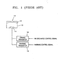
- FIG. 1 An apparatus for controlling the temperature of a head that heats a head substrate using only a main heater, i.e., without resistance heaters, has been suggested, as illustrated in FIG. 1 .
- a controller (not shown) drives a driving transistor 16, which has a larger capacity than a warming transistor 18, and allows enough current to flow through a main heater 14, which is a resistance heaters, to discharge ink.
- the warming transistor 18, which operates each ink chamber 13 of a head applies a warming pulse to the main heater 14 in response to a warming control signal received when the temperature of the head sensed by a temperature sensor (not shown) is lower than a predetermined temperature and maintains the heat at the predetermined temperature.
- the warming transistor 18 increases the temperature of the substrate using the main heater 14, a signal output from the warming transistor 18 to the main heater 14 must be limited to have a low enough voltage or short enough signal pulse width so as not to discharge ink 10 via a nozzle 12. Therefore, it takes a long time to increase the temperature of the substrate to the predetermined temperature due to a low heating temperature of the main heater 14.
- a method of heating a substrate using an operating resistance of a transistor and not including a resistance heater as a supplementary heater, as illustrated in FIG. 2 is disclosed in U.S. Patent No. 6,286,924 .
- a voltage source V D connected to a drain of the first pass FET 200 is supplied to a drain of a second pass FET 210, which includes a plurality of transistors, and a drain of an enable FET 220, via a source of the first pass FET 200.
- the drain voltage of the enable FET 220 is applied to a gate of a main heater driving FET 230, and when the gate voltage is at a high level, the current by a heater voltage flows to the ground via a main heater 240 and the main heater driving FET 230.
- An on-resistance of each of the first pass and second pass, and enable FETs 200, 210, and 220 is 200 ohms, which is higher than the resistance of the heater driving FET 230.
- the first pass, second pass, and enable FETs 200, 210, and 220 operate in response to control signals Q1 through Q5, and CE respectively applied to gates of the first pass, second pass, and enable FETs 200, 210, and 220, the first pass, second pass, and enable FETS 200, 210, and 220 are heated due to the on-resistance and increase the temperature of a head substrate.
- the first pass FET 200 always remains “on” and increases the temperature of the head substrate, thereby making it difficult to control the temperature of the head substrate.
- the heater driving FET 230 which is composed of a plurality of transistors (not shown), takes up most of the area of the head substrate, and the heatable first and second pass FETs 200 and 210 are uniformly disposed, thereby making it difficult to control the temperature of the head substrate.
- EP 658429 describes a control circuit for regulating the temperature in an ink-jet printhead.
- an apparatus for controlling a temperature of an ink jet head includes: a heater driving FET that is connected to a heater and applies heater voltage to the heater according to a waveform input to a gate of the heater driving FET; a current sensor that converts current flowing between a drain and a source of the heater driving FET into a voltage and outputs the voltage; a comparator that compares the voltage output from the current sensor with a predetermined reference voltage; a warming control signal generator that generates a warming control signal in the form of a pulse string; and a switching unit that receives an output signal of the comparator via a gate, and outputs the warming control signal according to the level of the output signal of the comparator by connecting with the gate of the heater driving FET.
- the present invention provides an apparatus for controlling the temperature of an ink jet head that has a fast temperature control response.
- the apparatus changes the operation conditions of a field-effect transistor (FET) for driving a heater inside a head substrate, and heats the head substrate using a switching loss of the FET for driving the heater and heat generated by a main heater.
- FET field-effect transistor
- the warming control signal may include a pulse string having a high duty cycle so that the heater driving FET can generate heat by causing a switching loss.
- the comparator may activate the first switching FET when the output voltage of the current sensor is lower than the reference voltage.
- the current sensor may be a shunt resistor connected between the source of the heater driving FET and the ground.
- the switching unit is a first switching FET may include a drain to which the warming control signal is input, a gate to which the output signal of the comparator is input, and a source connected to the gate of the heater driving FET.
- the switching unit may be connected in series with the first switching FET, and comprises a gate to which a discharge enable signal is input, a drain to which an ink discharge control signal of a printer is input, and a source that outputs the ink discharge control signal according to the level of the discharge enable signal.
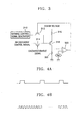
- FIG. 3 is a circuit diagram of an apparatus for controlling the temperature of an ink jet print head according to an embodiment of the present invention.
- the apparatus includes the following elements.
- a heater 316 which is a resistance heater, to heat ink.
- a first switching field effect transistor (FET) 312 outputs an inputted warming control signal in response to a signal input to a gate terminal.
- a second switching FET 314 outputs a common ink discharge control signal for heating the heater 316 when in an ink discharging mode.
- a heater driving FET 318 heats the heater 316 by supplying a current to the heater 316 in response to an output signal of the first or second switching FET 312 or 314 applied to a gate of the heater driving FET 318.
- the heater driving FET 318 is heated due to a switching loss in response to a pulse string of the warming control signal supplied to the gate of the heater driving FET 318.
- a current sensor 320 converts the current flowing through a drain and a source of the heater driving FET 318 into a voltage range, and outputs the voltage.
- a comparator 322 compares the voltage output from the current sensor 320 and a reference voltage Ref, and outputs a signal depending on the result of comparison to the gate of the first switching FET 312.
- a warming control signal generator 310 generates and outputs the warming control signal.
- the warming control signal generator 310 may be a micro controller.
- the printer When a printer prints text, the printer outputs an ink discharge control signal to a drain and a gate of the second switching FET 314 according to a discharge enable signal and font data that corresponds to text stored in a common font memory (not shown).
- a source terminal of the second switching FET 314 connected to a gate of the heater driving FET 318 passes the ink discharge control signal, to the heater driving FET 318 according to the discharge enable signal.
- the heater 316 is connected between the drain of the heater driving FET 318 and the heater voltage, and a current sensor 320, which is a shunt resistor, having low resistance, is connected between the source of the heater driving FET 318 and the ground to check the current flowing through the heater driving FET 318. Therefore, when the ink discharge control signal, as illustrated in FIG. 4 , is at a high level applied, the heater driving FET 318 is activated, and the heater 316 is heated due to the current flowing through the heater 316, and thus droplets of ink are discharged.
- the voltage across the current sensor 320 is input to a negative input end of the comparator 322, and is compared to the reference voltage Ref, which is input to a positive input end of the comparator 322. Since the inner resistance of the heater driving FET 318 increases as the temperature of the heater driving FET 318 decreases, and the heater power is divided among the heater 316, the heater driving FET 318, and the current sensor 320, the voltage across the current sensor 320 decrease when the temperature of the heater driving FET 318 is decreased. Therefore, when the voltage across the current sensor 320 is lower than the reference voltage Ref, an output of the comparator 322 is at a high level and is output to the gate of the first switching FET 312.
- the activated first switching FET 312 transmits the warming control signal to the gate of the heater driving FET 318, and thus raises the temperature of the heater 316 and the heater driving FET 318 to an appropriate temperature.
- FIG. 4A is a waveform diagram of the ink discharge control signal
- FIG. 4B is a waveform diagram of the warming control signal, which is composed of pulses having a shorter pulse width than a pulse width of the ink discharge control signal of FIG. 4B and a pulse string having a high duty cycle.
- the pulse of the warming control signal with high duty cycle warms the heater 316 to the appropriate temperature.
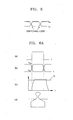
- the heater driving FET 318 is heated and increases the temperature of the head substrate due to a switching loss generated by inversion of the voltage V DS and current I DS between the drain and the source of the heater driving FET 318, as illustrated in FIG. 5 .
- FIG. 6A(a) is a view of the ink discharge control signal applied to the heater driving FET 318 illustrated in FIG. 3 .
- FIG. 6A(b) is a view of the voltage V DS and the current I DS between the drain and source of the head driving FET 318 caused by the ink discharge control signal
- FIG. 6A(c) is a view of the temperature of the heater 316
- FIG. 6A(d) is a view of the shape of a chamber discharging ink.
- FIG. 6B (a') illustrates the ink discharge control signal sent to the heater driving FET 318 illustrated in FIG. 3
- FIG. 6B (b') illustrates the voltage V DS and the current I DS between the drain and source of the head driving FET 318 caused by the ink discharge control signal
- FIG. 6B (c') is a view of the temperature of the heater 316
- FIG. 6B (d') is a view of the shape of a chamber in the head substrate heating mode.
- the pulse string of the warming control signal has a higher duty cycle than in the ink discharging mode and is applied to the gate of the heater driving FET 318.
- the temperature of the heater 316 does not increase to the temperature K required to generate the ink bubble, and the ink is maintained at an appropriate temperature.
- the heater driving FET 318 heats the head substrate using heat generated due to the switching loss, without requiring a transistor using a separate on-resistance or a supplementary heater, such as a resistance heater.
- an apparatus for controlling the temperature of an ink jet head with improved temperature control response maintains a head substrate at an appropriate temperature by heating a heater to a temperature lower than a temperature at which ink bubbles are generated using a warming control signal composed of a pulse string with a high duty cycle and at simultaneously heating a heater driving FET by using a switching loss when a temperature of the heater driving FET is lower than a reference temperature.
Landscapes
- Particle Formation And Scattering Control In Inkjet Printers (AREA)
- Ink Jet (AREA)
Claims (5)
- Appareil de régulation de la température d'une tête à jet d'encre, comprenant :un générateur de signal de commande de réchauffage (310) qui est agencé pour générer un signal de commande de réchauffage sous la forme d'un train d'impulsions ;caractérisé en ce qu'il comprend en outre un élément chauffant (316) et un transistor à effet de champ (FET) (318) commandant l'élément chauffant, qui est connecté audit élément chauffant (316) pour appliquer une tension de chauffage à l'élément chauffant en fonction d'une entrée de forme d'onde à une porte du FET commandant l'élément chauffant ;un capteur de courant (320) qui est agencé pour convertir le courant circulant entre un drain et une source du FET commandant l'élément chauffant en une tension et fournit la tension de sortie ;un comparateur (322) qui est agencé pour comparer la tension de sortie du capteur de courant à une tension de référence prédéterminée ; etune unité de commutation (312, 314) qui est agencée pour recevoir un signal de sortie du comparateur via une porte, et fournit le signal de commande de réchauffage en fonction du niveau du signal de sortie du comparateur par connexion avec la porte du FET commandant l'élément chauffant ;dans lequel le signal de commande de réchauffage comprend un train d'impulsions ayant un cycle de service élevé de sorte que le FET commandant l'élément chauffant puisse générer de la chaleur en causant un affaiblissement de commutation.
- Appareil selon la revendication 1, dans lequel le capteur de courant (320) est une résistance shunt connectée entre la source du FET commandant l'élément chauffant et la terre.
- Appareil selon l'une quelconque des revendications précédentes, dans lequel l'unité de commutation comprend un premier FET de commutation (312) qui comprend un drain auquel est fourni le signal de commande de réchauffage, une porte à laquelle est fourni le signal de sortie du comparateur, et une source connectée à la porte du FET commandant l'élément chauffant.
- Appareil selon la revendication 3, dans lequel le comparateur (322) active le premier FET de commutation lorsque la tension de sortie du capteur de courant est inférieure à la tension de référence.
- Appareil selon la revendication 4, dans lequel l'unité de commutation comprend en outre un deuxième FET de commutation (314), et comprend une porte à laquelle est fourni un signal de validation de décharge, un drain auquel est fourni un signal de commande de décharge d'encre d'une imprimante, et une source qui fournit le signal de commande de décharge d'encre en fonction du niveau du signal de validation de décharge au FET commandant l'élément chauffant (318).
Applications Claiming Priority (2)
| Application Number | Priority Date | Filing Date | Title |
|---|---|---|---|
| KR2003083040 | 2003-11-21 | ||
| KR10-2003-0083040A KR100513733B1 (ko) | 2003-11-21 | 2003-11-21 | 잉크젯 헤드 온도 제어 장치 |
Publications (2)
| Publication Number | Publication Date |
|---|---|
| EP1533121A1 EP1533121A1 (fr) | 2005-05-25 |
| EP1533121B1 true EP1533121B1 (fr) | 2009-10-21 |
Family
ID=34431808
Family Applications (1)
| Application Number | Title | Priority Date | Filing Date |
|---|---|---|---|
| EP04257192A Expired - Lifetime EP1533121B1 (fr) | 2003-11-21 | 2004-11-19 | Dispositif de contrôle de la température d'une tête à jet d'encre |
Country Status (5)
| Country | Link |
|---|---|
| US (1) | US7201461B2 (fr) |
| EP (1) | EP1533121B1 (fr) |
| JP (1) | JP4646291B2 (fr) |
| KR (1) | KR100513733B1 (fr) |
| DE (1) | DE602004023680D1 (fr) |
Families Citing this family (10)
| Publication number | Priority date | Publication date | Assignee | Title |
|---|---|---|---|---|
| JP5294682B2 (ja) * | 2008-04-30 | 2013-09-18 | キヤノン株式会社 | インクジェットヘッド用基板、インクジェットヘッドおよび該インクジェットヘッドを備えたインクジェット記録装置 |
| US8161891B2 (en) | 2010-04-01 | 2012-04-24 | Blue Sky Innovation Group, Inc. | Expandable table |
| CN103619601B (zh) * | 2011-07-01 | 2015-10-21 | 惠普发展公司,有限责任合伙企业 | 调节打印头温度的方法和装置 |
| CN105835531B (zh) * | 2015-01-16 | 2018-06-12 | 研能科技股份有限公司 | 快速成型装置的打印模块 |
| TWI626169B (zh) * | 2015-01-16 | 2018-06-11 | Microjet Technology Co., Ltd | 快速成型裝置之列印模組之噴液晶片 |
| US10875296B2 (en) | 2017-02-27 | 2020-12-29 | Hewlett-Packard Development Company, L.P. | Nozzle sensor protection |
| JP6776971B2 (ja) * | 2017-03-27 | 2020-10-28 | 株式会社島津製作所 | 真空ポンプおよびポンプ一体型の電源装置 |
| WO2019013788A1 (fr) * | 2017-07-12 | 2019-01-17 | Hewlett-Packard Development Company, L.P. | Régulateur de tension pour commande de grille de commutateur côté bas |
| JP7362396B2 (ja) * | 2019-09-27 | 2023-10-17 | キヤノン株式会社 | 液体吐出ヘッド |
| JP2025148702A (ja) * | 2024-03-26 | 2025-10-08 | 京セラドキュメントソリューションズ株式会社 | 画像形成装置 |
Family Cites Families (6)
| Publication number | Priority date | Publication date | Assignee | Title |
|---|---|---|---|---|
| US4590362A (en) | 1983-04-20 | 1986-05-20 | Ricoh Company, Ltd. | Drive circuit for temperature control heater in ink jet printer |
| US5475405A (en) * | 1993-12-14 | 1995-12-12 | Hewlett-Packard Company | Control circuit for regulating temperature in an ink-jet print head |
| US5815180A (en) * | 1997-03-17 | 1998-09-29 | Hewlett-Packard Company | Thermal inkjet printhead warming circuit |
| US6322189B1 (en) | 1999-01-13 | 2001-11-27 | Hewlett-Packard Company | Multiple printhead apparatus with temperature control and method |
| US6286924B1 (en) | 1999-09-14 | 2001-09-11 | Lexmark International, Inc. | Apparatus and method for heating ink jet printhead |
| JP2002321368A (ja) * | 2001-04-24 | 2002-11-05 | Cyber Graphics Kk | インクジェットプリンタ方式 |
-
2003
- 2003-11-21 KR KR10-2003-0083040A patent/KR100513733B1/ko not_active Expired - Fee Related
-
2004
- 2004-11-19 DE DE602004023680T patent/DE602004023680D1/de not_active Expired - Lifetime
- 2004-11-19 JP JP2004336536A patent/JP4646291B2/ja not_active Expired - Fee Related
- 2004-11-19 EP EP04257192A patent/EP1533121B1/fr not_active Expired - Lifetime
- 2004-11-19 US US10/991,930 patent/US7201461B2/en not_active Expired - Fee Related
Also Published As
| Publication number | Publication date |
|---|---|
| US7201461B2 (en) | 2007-04-10 |
| US20050110819A1 (en) | 2005-05-26 |
| KR100513733B1 (ko) | 2005-09-08 |
| JP2005153527A (ja) | 2005-06-16 |
| EP1533121A1 (fr) | 2005-05-25 |
| DE602004023680D1 (de) | 2009-12-03 |
| JP4646291B2 (ja) | 2011-03-09 |
| KR20050049152A (ko) | 2005-05-25 |
Similar Documents
| Publication | Publication Date | Title |
|---|---|---|
| US7802858B2 (en) | Element board for printhead, printhead and printhead control method | |
| EP1004442B1 (fr) | Variation de la quantité d'énergie de commande appliquée à une cartouche d'impression à jet d'encre en fonction du mode d'impression utilisé | |
| EP1533121B1 (fr) | Dispositif de contrôle de la température d'une tête à jet d'encre | |
| EP1366900A2 (fr) | Imprimante comportant des moyens de prévention de surchauffe | |
| US7850262B2 (en) | Head substrate, printhead, head cartridge, and printing apparatus | |
| JP2815959B2 (ja) | 液体噴射記録装置 | |
| EP0763429B2 (fr) | Chauffage d'une tête d'impression à jet d'encre | |
| JP4035253B2 (ja) | 記録ヘッド及びその記録ヘッドを用いた記録装置 | |
| TW200540021A (en) | Printhead substrate, printhead, head cartridge, and printing apparatus | |
| JP4532890B2 (ja) | 記録ヘッドおよび該記録ヘッドを備えた記録装置 | |
| US8132895B2 (en) | Printhead substrate, printhead, head cartridge, and printing apparatus | |
| JPH06135002A (ja) | インクジェット記録装置 | |
| JPH06344638A (ja) | 記録装置及び該装置における消費電力制御方法 | |
| JPH03234629A (ja) | 画像記録装置 | |
| JP5385586B2 (ja) | ヘッド基板、記録ヘッド、ヘッドカートリッジ、及び記録装置 | |
| JP2005169866A (ja) | 記録ヘッド及びその記録ヘッドを用いた記録装置 | |
| JPH1044411A (ja) | インクジェットプリントヘッドの保温制御装置、インクジェットプリントヘッドおよびインクジェットプリント装置 | |
| JP4455013B2 (ja) | 記録ヘッドの駆動方法、記録ヘッド、及び記録装置 | |
| JP2024085239A (ja) | 電源装置及び画像形成装置 | |
| JP4289976B2 (ja) | 記録ヘッドの駆動方法、記録ヘッドの素子基板、記録ヘッド、ヘッドカートリッジ、及び記録装置 | |
| JP2009143017A (ja) | 素子基板、及びその素子基板を有する記録ヘッド、ヘッドカートリッジ、記録装置 | |
| JPH0531899A (ja) | サーマルインクジエツトヘツド | |
| JP2001179958A (ja) | インクジェット記録装置 | |
| JP2004209885A (ja) | インクジェット記録ヘッド | |
| KR20040082687A (ko) | 히터편차 보상이 가능한 잉크젯 프린터 및 그에 의한히터편차 보상방법 |
Legal Events
| Date | Code | Title | Description |
|---|---|---|---|
| PUAI | Public reference made under article 153(3) epc to a published international application that has entered the european phase |
Free format text: ORIGINAL CODE: 0009012 |
|
| AK | Designated contracting states |
Kind code of ref document: A1 Designated state(s): AT BE BG CH CY CZ DE DK EE ES FI FR GB GR HU IE IS IT LI LU MC NL PL PT RO SE SI SK TR |
|
| AX | Request for extension of the european patent |
Extension state: AL HR LT LV MK YU |
|
| 17P | Request for examination filed |
Effective date: 20050907 |
|
| AKX | Designation fees paid |
Designated state(s): DE FR GB |
|
| 17Q | First examination report despatched |
Effective date: 20071010 |
|
| GRAP | Despatch of communication of intention to grant a patent |
Free format text: ORIGINAL CODE: EPIDOSNIGR1 |
|
| GRAS | Grant fee paid |
Free format text: ORIGINAL CODE: EPIDOSNIGR3 |
|
| GRAA | (expected) grant |
Free format text: ORIGINAL CODE: 0009210 |
|
| AK | Designated contracting states |
Kind code of ref document: B1 Designated state(s): DE FR GB |
|
| REG | Reference to a national code |
Ref country code: GB Ref legal event code: FG4D |
|
| REF | Corresponds to: |
Ref document number: 602004023680 Country of ref document: DE Date of ref document: 20091203 Kind code of ref document: P |
|
| PLBE | No opposition filed within time limit |
Free format text: ORIGINAL CODE: 0009261 |
|
| STAA | Information on the status of an ep patent application or granted ep patent |
Free format text: STATUS: NO OPPOSITION FILED WITHIN TIME LIMIT |
|
| 26N | No opposition filed |
Effective date: 20100722 |
|
| PGFP | Annual fee paid to national office [announced via postgrant information from national office to epo] |
Ref country code: FR Payment date: 20131115 Year of fee payment: 10 Ref country code: GB Payment date: 20131112 Year of fee payment: 10 Ref country code: DE Payment date: 20131113 Year of fee payment: 10 |
|
| REG | Reference to a national code |
Ref country code: DE Ref legal event code: R119 Ref document number: 602004023680 Country of ref document: DE |
|
| GBPC | Gb: european patent ceased through non-payment of renewal fee |
Effective date: 20141119 |
|
| REG | Reference to a national code |
Ref country code: FR Ref legal event code: ST Effective date: 20150731 |
|
| PG25 | Lapsed in a contracting state [announced via postgrant information from national office to epo] |
Ref country code: DE Free format text: LAPSE BECAUSE OF NON-PAYMENT OF DUE FEES Effective date: 20150602 Ref country code: GB Free format text: LAPSE BECAUSE OF NON-PAYMENT OF DUE FEES Effective date: 20141119 |
|
| PG25 | Lapsed in a contracting state [announced via postgrant information from national office to epo] |
Ref country code: FR Free format text: LAPSE BECAUSE OF NON-PAYMENT OF DUE FEES Effective date: 20141201 |