EP1532907B1 - Electric smokeless roaster - Google Patents
Electric smokeless roaster Download PDFInfo
- Publication number
- EP1532907B1 EP1532907B1 EP03717667A EP03717667A EP1532907B1 EP 1532907 B1 EP1532907 B1 EP 1532907B1 EP 03717667 A EP03717667 A EP 03717667A EP 03717667 A EP03717667 A EP 03717667A EP 1532907 B1 EP1532907 B1 EP 1532907B1
- Authority
- EP
- European Patent Office
- Prior art keywords
- grill
- casing
- unit
- suction
- electric
- Prior art date
- Legal status (The legal status is an assumption and is not a legal conclusion. Google has not performed a legal analysis and makes no representation as to the accuracy of the status listed.)
- Expired - Lifetime
Links
- XLYOFNOQVPJJNP-UHFFFAOYSA-N water Substances O XLYOFNOQVPJJNP-UHFFFAOYSA-N 0.000 claims abstract description 36
- 239000000428 dust Substances 0.000 claims abstract description 31
- 239000003595 mist Substances 0.000 claims description 27
- CBENFWSGALASAD-UHFFFAOYSA-N Ozone Chemical compound [O-][O+]=O CBENFWSGALASAD-UHFFFAOYSA-N 0.000 claims description 25
- 239000002351 wastewater Substances 0.000 claims description 15
- 239000003054 catalyst Substances 0.000 claims description 9
- 239000003610 charcoal Substances 0.000 claims description 7
- 238000011144 upstream manufacturing Methods 0.000 claims description 3
- 239000007789 gas Substances 0.000 abstract description 6
- 239000000779 smoke Substances 0.000 description 42
- 235000013305 food Nutrition 0.000 description 29
- 239000000463 material Substances 0.000 description 28
- 235000013372 meat Nutrition 0.000 description 16
- 230000000694 effects Effects 0.000 description 8
- 238000010411 cooking Methods 0.000 description 7
- 239000002245 particle Substances 0.000 description 6
- 230000001954 sterilising effect Effects 0.000 description 6
- 238000004332 deodorization Methods 0.000 description 5
- 230000003287 optical effect Effects 0.000 description 4
- 230000001877 deodorizing effect Effects 0.000 description 3
- 229910052751 metal Inorganic materials 0.000 description 3
- 239000002184 metal Substances 0.000 description 3
- 238000000034 method Methods 0.000 description 3
- 238000011045 prefiltration Methods 0.000 description 3
- 235000015067 sauces Nutrition 0.000 description 3
- 235000014102 seafood Nutrition 0.000 description 3
- 238000004659 sterilization and disinfection Methods 0.000 description 3
- 241000287828 Gallus gallus Species 0.000 description 2
- ATUOYWHBWRKTHZ-UHFFFAOYSA-N Propane Chemical compound CCC ATUOYWHBWRKTHZ-UHFFFAOYSA-N 0.000 description 2
- 230000003247 decreasing effect Effects 0.000 description 2
- 238000010438 heat treatment Methods 0.000 description 2
- 239000007788 liquid Substances 0.000 description 2
- 238000001179 sorption measurement Methods 0.000 description 2
- 241000251468 Actinopterygii Species 0.000 description 1
- 229920000742 Cotton Polymers 0.000 description 1
- 241000237502 Ostreidae Species 0.000 description 1
- 241000237509 Patinopecten sp. Species 0.000 description 1
- GWEVSGVZZGPLCZ-UHFFFAOYSA-N Titan oxide Chemical compound O=[Ti]=O GWEVSGVZZGPLCZ-UHFFFAOYSA-N 0.000 description 1
- 241000894431 Turbinidae Species 0.000 description 1
- 238000010521 absorption reaction Methods 0.000 description 1
- 238000004378 air conditioning Methods 0.000 description 1
- 229910052782 aluminium Inorganic materials 0.000 description 1
- XAGFODPZIPBFFR-UHFFFAOYSA-N aluminium Chemical compound [Al] XAGFODPZIPBFFR-UHFFFAOYSA-N 0.000 description 1
- QVGXLLKOCUKJST-UHFFFAOYSA-N atomic oxygen Chemical compound [O] QVGXLLKOCUKJST-UHFFFAOYSA-N 0.000 description 1
- 235000021168 barbecue Nutrition 0.000 description 1
- 238000004140 cleaning Methods 0.000 description 1
- 239000000567 combustion gas Substances 0.000 description 1
- 230000001143 conditioned effect Effects 0.000 description 1
- 238000000354 decomposition reaction Methods 0.000 description 1
- 238000009792 diffusion process Methods 0.000 description 1
- 238000001035 drying Methods 0.000 description 1
- 238000001704 evaporation Methods 0.000 description 1
- 230000008020 evaporation Effects 0.000 description 1
- 235000013882 gravy Nutrition 0.000 description 1
- 238000009434 installation Methods 0.000 description 1
- 230000001678 irradiating effect Effects 0.000 description 1
- 230000007794 irritation Effects 0.000 description 1
- 230000005722 itchiness Effects 0.000 description 1
- 235000019198 oils Nutrition 0.000 description 1
- 230000003647 oxidation Effects 0.000 description 1
- 238000007254 oxidation reaction Methods 0.000 description 1
- 230000001590 oxidative effect Effects 0.000 description 1
- 239000001301 oxygen Substances 0.000 description 1
- 229910052760 oxygen Inorganic materials 0.000 description 1
- 235000020636 oyster Nutrition 0.000 description 1
- 230000003405 preventing effect Effects 0.000 description 1
- 239000001294 propane Substances 0.000 description 1
- 238000000746 purification Methods 0.000 description 1
- 230000005855 radiation Effects 0.000 description 1
- 230000000630 rising effect Effects 0.000 description 1
- 235000020637 scallop Nutrition 0.000 description 1
- 239000007787 solid Substances 0.000 description 1
- OGIDPMRJRNCKJF-UHFFFAOYSA-N titanium oxide Inorganic materials [Ti]=O OGIDPMRJRNCKJF-UHFFFAOYSA-N 0.000 description 1
- 210000000689 upper leg Anatomy 0.000 description 1
Images


Classifications
-
- A—HUMAN NECESSITIES
- A47—FURNITURE; DOMESTIC ARTICLES OR APPLIANCES; COFFEE MILLS; SPICE MILLS; SUCTION CLEANERS IN GENERAL
- A47J—KITCHEN EQUIPMENT; COFFEE MILLS; SPICE MILLS; APPARATUS FOR MAKING BEVERAGES
- A47J37/00—Baking; Roasting; Grilling; Frying
- A47J37/06—Roasters; Grills; Sandwich grills
-
- F—MECHANICAL ENGINEERING; LIGHTING; HEATING; WEAPONS; BLASTING
- F24—HEATING; RANGES; VENTILATING
- F24C—DOMESTIC STOVES OR RANGES ; DETAILS OF DOMESTIC STOVES OR RANGES, OF GENERAL APPLICATION
- F24C15/00—Details
- F24C15/20—Removing cooking fumes
- F24C15/2042—Devices for removing cooking fumes structurally associated with a cooking range e.g. downdraft
-
- A—HUMAN NECESSITIES
- A47—FURNITURE; DOMESTIC ARTICLES OR APPLIANCES; COFFEE MILLS; SPICE MILLS; SUCTION CLEANERS IN GENERAL
- A47J—KITCHEN EQUIPMENT; COFFEE MILLS; SPICE MILLS; APPARATUS FOR MAKING BEVERAGES
- A47J37/00—Baking; Roasting; Grilling; Frying
-
- B—PERFORMING OPERATIONS; TRANSPORTING
- B03—SEPARATION OF SOLID MATERIALS USING LIQUIDS OR USING PNEUMATIC TABLES OR JIGS; MAGNETIC OR ELECTROSTATIC SEPARATION OF SOLID MATERIALS FROM SOLID MATERIALS OR FLUIDS; SEPARATION BY HIGH-VOLTAGE ELECTRIC FIELDS
- B03C—MAGNETIC OR ELECTROSTATIC SEPARATION OF SOLID MATERIALS FROM SOLID MATERIALS OR FLUIDS; SEPARATION BY HIGH-VOLTAGE ELECTRIC FIELDS
- B03C3/00—Separating dispersed particles from gases or vapour, e.g. air, by electrostatic effect
- B03C3/01—Pretreatment of the gases prior to electrostatic precipitation
- B03C3/011—Prefiltering; Flow controlling
-
- B—PERFORMING OPERATIONS; TRANSPORTING
- B03—SEPARATION OF SOLID MATERIALS USING LIQUIDS OR USING PNEUMATIC TABLES OR JIGS; MAGNETIC OR ELECTROSTATIC SEPARATION OF SOLID MATERIALS FROM SOLID MATERIALS OR FLUIDS; SEPARATION BY HIGH-VOLTAGE ELECTRIC FIELDS
- B03C—MAGNETIC OR ELECTROSTATIC SEPARATION OF SOLID MATERIALS FROM SOLID MATERIALS OR FLUIDS; SEPARATION BY HIGH-VOLTAGE ELECTRIC FIELDS
- B03C3/00—Separating dispersed particles from gases or vapour, e.g. air, by electrostatic effect
- B03C3/017—Combinations of electrostatic separation with other processes, not otherwise provided for
-
- B—PERFORMING OPERATIONS; TRANSPORTING
- B03—SEPARATION OF SOLID MATERIALS USING LIQUIDS OR USING PNEUMATIC TABLES OR JIGS; MAGNETIC OR ELECTROSTATIC SEPARATION OF SOLID MATERIALS FROM SOLID MATERIALS OR FLUIDS; SEPARATION BY HIGH-VOLTAGE ELECTRIC FIELDS
- B03C—MAGNETIC OR ELECTROSTATIC SEPARATION OF SOLID MATERIALS FROM SOLID MATERIALS OR FLUIDS; SEPARATION BY HIGH-VOLTAGE ELECTRIC FIELDS
- B03C3/00—Separating dispersed particles from gases or vapour, e.g. air, by electrostatic effect
- B03C3/34—Constructional details or accessories or operation thereof
- B03C3/36—Controlling flow of gases or vapour
- B03C3/368—Controlling flow of gases or vapour by other than static mechanical means, e.g. internal ventilator or recycler
-
- B—PERFORMING OPERATIONS; TRANSPORTING
- B03—SEPARATION OF SOLID MATERIALS USING LIQUIDS OR USING PNEUMATIC TABLES OR JIGS; MAGNETIC OR ELECTROSTATIC SEPARATION OF SOLID MATERIALS FROM SOLID MATERIALS OR FLUIDS; SEPARATION BY HIGH-VOLTAGE ELECTRIC FIELDS
- B03C—MAGNETIC OR ELECTROSTATIC SEPARATION OF SOLID MATERIALS FROM SOLID MATERIALS OR FLUIDS; SEPARATION BY HIGH-VOLTAGE ELECTRIC FIELDS
- B03C3/00—Separating dispersed particles from gases or vapour, e.g. air, by electrostatic effect
- B03C3/34—Constructional details or accessories or operation thereof
- B03C3/40—Electrode constructions
- B03C3/45—Collecting-electrodes
- B03C3/47—Collecting-electrodes flat, e.g. plates, discs, gratings
Definitions
- the present invention relates to an electric smokeless roaster which is installed in grilled food restaurants, grilled meat restaurants, and other eating places, and which generates neither smoke nor odor to the inside and outside of the restaurants.
- Grilled meat restaurants or grilled chicken restaurants are filled with smoke and smell of meats or other food materials and the smell stays on clothes and hair, because of which people dressed up in formal attire or expensive coats hesitate to enter these restaurants.
- hooded type roasters wherein a hood is installed directly above the grill to suck smoke rising from the meat and other food materials placed on the grill
- smokeless meat roasters wherein a suction hole is provided on the periphery of the grill to suck smoke generated from the food materials from a side of the grill
- the former the hooded type, has the drawbacks that the generated smoke is not completely sucked, and that the air-conditioning efficiency is lowered because the roaster also sucks in the conditioned room air.
- the latter the smokeless meat roaster, has the problem that the moisture on the heated food materials and the room air are also sucked in together with smoke through the suction hole located on the side above the grill, thereby drying up the grilled food materials to harm the taste thereof.
- the present inventors have previously disclosed a cooking device with a smoke exhaust system in Japanese Examined Patent Publication No. Sho 59-49004 .
- a cooking device having its heat source on the lower side, as the smoke generated from food materials rises upwardly, it appears to be generated from the entire surface of the food materials.
- most of the smoke is actually generated from the part of the food materials nearest to the heat source, that is, the underside of the food materials.
- the invention was made based on the finding. According to the invention, smoke is collected from a suction hole provided around the grill on the lower side thereof and exhausted through a duct. The invention thus provided a cooking device that hardly generates smoke.
- an object that the invention aims to achieve is to provide a smokeless roaster which does not need the duct that was installed inside and outside a restaurant and which hardly generates harmful gasses such as NO x .
- the invention in a first aspect is an electric smokeless roaster comprising an electric heater unit installed in an upper part of a casing, a water pan provided in a lower part of the heater unit, a grill arranged above the heater unit, a table mounted on an upper surface of the casing and formed with an opening at a position corresponding to the above grill, a suction unit provided on a periphery of the grill and including a suction port for sucking in air around the grill, an electric dust collecting unit provided inside the casing for dedusting air sucked in through the suction unit, and a deodorizer provided in the casing for decomposing odor components contained in the air dedusted by the electric dust collecting unit and for exhausting the air out of the casing.
- the electric dust collecting unit for catching and collecting oil components contained in the smoke, and the deodorizer for decomposing fine oil mist particles that cannot be caught by the electric dust collecting unit and odor components are provided on the periphery of the food materials placed on the grill part of the roaster, that is, inside the device that sucks in smoke generated from the upper or lower side of the food materials from the suction port and exhausts the smoke to the outside of the casing.
- the purified smoke is exhausted to the outside of the casing, that is, into the interior of the restaurant. Since smoke purification is completed within the device inside the casing, it is unnecessary to install a duct inside and outside of the restaurant and the equipment therefor.
- the heater unit uses electric power for its heat source, it does not generate combustion gas as with city gas or propane gas, and therefore NO x is hardly generated. Accordingly, the roaster can be installed in any place where there is an electric power source.
- a second aspect of the present invention is that the suction port of the suction unit according to the first aspect is provided on a periphery of the heater unit below the grill.
- Food materials that are thin and contain high fat, such as sliced meat, generate smoke from the underside where the temperature is the highest.
- the smoke is effectively sucked in and removed, and processed to remove the smell.
- a negative pressure is created under the grill, whereby the efficiency of the smoke sucking effect is increased.
- a third aspect of the present invention is that the suction port of the suction unit according to the first aspect is provided on a periphery above the grill.
- Some food materials placed on the grill for example, seafood, which are thick, should be cooked well. Since these food materials do not generate smoke as evidently as meat, by sucking in air from the periphery above the grill, the air passing through the heater unit is made contact with the food materials before it is exhausted, whereby the heating efficiency is increased and the roasting time is shortned.
- a fourth aspect of the present invention is that, in the first aspect, a downside type suction unit having a suction port below the grill and an upside type suction unit having a suction port on a periphery above the grill are detachably set in the casing so that they are replaceable.
- the suction unit can be replaced and used depending on the menu. For example, the downside type suction unit is attached when grilling meat, while the upside type suction unit is attached when cooking fresh seafood barbecue.
- a fifth aspect of the present invention is that the suction port of the suction unit according to the second aspect includes an air director plate protruded on an upper part on the side of the grill.
- a sixth aspect of the present invention is that the suction unit according to any one of the first to fifth aspects comprises a detachable guide plate for guiding air that is sucked in a horizontal direction from the suction port into a vertical direction, a detachable oil mist collecting chute arranged at a predetermined interval with an exit of the guide plate, a detachable oil tank for accumulating oil collected in the oil mist collecting chute, and a duct for guiding air that has passed through the oil mist collecting chute toward the electric dust collecting unit.
- Smoke generated from food materials, in particular, meat contains a large amount of oil components.
- oil mist is cooled down on the wall surface, and liquefied oil adheres on the wall surface, drips down, and accumulates in a lower part of the smoke passage, which makes oil removal operation become troublesome.
- smoke is directed into the oil mist collecting chute by the guide plate and liquefied.
- the liquefied oil travels along the oil mist collecting chute and accumulates in the oil tank.
- the oil mist is thus liquefied at the entrance of the sucked in smoke passage, which is the part where oil is most likely to adhere. Since the guide plate, the oil mist collecting chute, and the oil tank are detachable, these can be removed after the restaurant is closed to clean off the oil adhered on the guide plate and the oil mist collecting chute and to dispose of the oil accumulated in the oil tank.
- a seventh aspect of the present invention is that, in any one of the first to sixth aspects, an oil spout is provided at a side end of the water pan, so that wastewater that has overflowed from the oil spout is collected in a removable wastewater collecting tank accommodated in the casing.
- the oil spout is provided at one side end of the water pan, and new water is poured into the water pan slowly from the opposite side of this oil spout.
- This causes the high-temperature wastewater containing much oil, which has a lower specific weight than water, to overflow from the oil spout and be replaced with the new water.
- the wastewater that has overflowed from the oil spout is collected in the removable wastewater collecting tank accommodated in the casing. When the wastewater collecting tank becomes full, the tank is removed to dispose of the wastewater inside.
- An eighth aspect of the invention is that, in the seventh aspect, the water pan is detachable from a side of the casing.
- the water in the water pan is replaced by pouring new water from an upper part during the restaurant's open hours, this does not remove the dirt completely. Therefore, the water pan may be removed in a horizontal direction from the side of the casing to be cleaned after the restaurant is closed or when there are no customers.
- the deodorizer comprises an ozone generating part.
- the electric dust collecting unit Since the electric dust collecting unit has a powerful oil mist collecting capability, there is hardly any visible gas in the exhaust air. The smell nevertheless remains strongly and, therefore, the odor components are decomposed by ozone generated from the ozone generating part. Unreacted ozone is mostly adsorbed by the active charcoal filter or decomposed by the ozone decomposing catalyst, so that the exhaust air contains residual ozone of 0.06ppm or lower, which is safe when it is exhausted.
- a ninth aspect of the invention is that, in the ninth aspect, the deodorizer alone is operable for a predetermined period of time.
- Ozone generated from the ozone generating part has a sterilizing effect in addition to the deodorizing effect. Therefore, after the restaurant is closed, by operating the deodorizer alone for the duration set by a timer or the like, the air is deodorized and sterilized while circulating in the empty restaurant during the closed hours until it is open again.
- a suction fan is installed between the electric dust collecting unit and the deodorizer according to any one of the first to tenth aspects and that a casing of the deodorizer has a shape that can function as a muffler.
- the suction fan would normally be installed downstream of the deodorizer, which is the component in the utmost end; however, by installing the suction fan downstream of the electric dust collecting unit and upstream of the deodorizer, the deodorizer can be used also as a muffler to prevent the suction fan from generating noise inside the restaurant.
- an electric heater unit 2 is provided in an upper part of a casing 1 that is installed on a floor surface.
- This heater unit 2 includes four far infrared sheathed heaters 3 arranged in parallel, and is supplied with power by plugging a power receiving terminal 4 into a power source unit 5 from above.
- a water pan 6 that can be set in and removed from the casing 1 in a lateral direction is installed.
- a table 7 having an opening at the center thereof is fixed.
- a frame-like table plate 8 is detachably mounted in the opening of the table 7, and a grill 9 is placed on a flanged part of the opening in the table plate 8.
- a suction unit 10 having a suction port 11 for sucking in air below the grill 9 is provided on both sides of the heater unit 2, as shown in Fig. 2 .
- the sucked air passes through the suction unit 10 and flows through a duct 20 and an electric dust collecting unit 30 as shown in Fig. 1 .
- a sirocco fan 40 is arranged downstream of the electric dust collecting unit 30, so that the air that has passed through the electric dust collecting unit 30 is sent to a deodorizer 50.
- the structure of the suction unit 10 will be described in more detail with reference to Fig. 2 .
- a horizontal air director plate 12 so that smoke generated from the lower part of the meat M or the like placed on the grill 9 is sucked in intensively and efficiently.
- the air sucked in horizontal direction is then oriented into a vertical direction by guide plates 13.
- an oil mist collecting chute 14 having a V-shaped cross section is arranged at a predetermined interval with the guide plates 13.
- the oil mist collecting chute 14A has a hole (not shown) at one location in the longitudinal direction thereof, so that liquefied oil is accumulated in an oil tank 15 that supports the oil mist collecting chute 14.
- the suction unit 10 can be disassembled and dismounted from the top so that the oil mist collecting chute 14 and the oil tank 15 can be cleaned.
- a beak-like oil spout 17 is protruded at the end on one side of the water pan 6. Liquid that has overflowed from this oil spout 17 flows into a receptor metal fitting 18 provided in the casing 1. A pipe 19 is formed in the lower part of the receptor metal fitting 18, so that the liquid is collected through a hose 21 into a wastewater collecting tank 22 (see Fig. 1 ) accommodated in the casing 1.
- the electric dust collecting unit 30 comprises a pre-filter 31 and a high voltage collector 32, as shown in Fig. 1 .
- the pre-filter 31 removes large-particle dust in the air sucked in from the duct 20 by the sirocco fan 40 so as to ensure that the successive high-voltage collector 32 operates normally.
- This pre-filter 31 is made of, for example, a combination of aluminum mesh filter and resin-bonded cotton filter, and can be reused after cleaning off adhered dust.
- the high-voltage collector 32 includes a plurality of electrodes arranged at predetermined intervals, to which positive and negative voltages are applied to electrify particles in the air passing through the electrodes to be positive or negative so that the particles are attracted to the electrodes.
- the electric dust collecting unit 30 removes most of the particles in the sucked air.
- the sirocco fan 40 is provided downstream of the electric dust collecting unit 30 to suck in air.
- adhesion of oil components on the sirocco fan 40 is prevented as much as possible.
- the strong smell still remains in the air dedusted by the electric dust collecting unit 30, the air is deodorized by the deodorizer 50 subsequently.
- the deodorizer 50 comprises an optical catalyst filter 51, an ozone generating part 52, an active charcoal filter 53A, and an ozone decomposing catalyst 53B.
- the optical catalyst filter 51 has the functions of oxidizing and decomposing odor, as well as sterilizing, by the strong oxidation effect of active oxygen and hydroxyl radicals that are generated, for example, by irradiating ultraviolet rays to titanium oxide.
- the ozone generating part 52 generates ozone for deodorization and sterilization.
- the active charcoal filter 53A performs primary deodorization by the effect of the active charcoal.
- the ozone decomposing catalyst 53B decomposes remains of the ozone generated from the ozone generating part 52 after deodorization and sterilization so that the concentration of ozone exhausted in the room does not exceed a standard value.
- the air deodorized by the deodorizer 50 is diffused by a diffusion plate 57 and exhausted out of the casing 1.
- Ozone generated from the ozone generating part 52 has a sterilizing effect in addition to the deodorizing effect. Therefore, after the restaurant is closed, by operating the sirocco fan 40 and the deodorizer 50 alone, the air in the empty restaurant is deodorized and sterilized while circulating.
- the operating time can suitably be set using a timer or the like.
- the sirocco fan 40 makes noises when it is driven to rotate.
- a muffler is normally provided downstream of the deodorizer 50 that is the air exit.
- the casing of the deodorizer 50 is constructed in the shape of a muffler comprising an expanding horn 54, a drum part 55, and a reducing horn 56, so that the deodorizer also functions as a muffler to make the casing 1 compact.
- Power is turned on to start operating the heater unit 2, the electric dust collecting unit 30, the sirocco fan 40, and the deodorizer 50.
- food materials placed on the grill 9 are heated from below by the far infrared sheathed heaters 3 in the heater unit 2.
- Smoke generated from the lower side of the heated food materials and air containing a large amount of oil components are sucked in a horizontal direction by the function of the air director plate 12 in the suction unit 10, oriented from the suction port 11 into a vertical direction by the guide plates 13, and, as they make contact with the surface of the oil mist collecting chute 14, sucked through the hole 16 into the duct 20.
- the high-temperature air containing oil and other components is cooled down on the surfaces of the guide plates 13 and the oil mist collecting chute 14, whereby the oil mist is liquefied and adheres on the surfaces of the guide plates 13 and the oil mist collecting chute 14.
- the adhered oil travels on the surface of the guide plates 13 and drips down into the oil mist collecting chute 14.
- the dropped oil travels along a lengthwise direction of the oil mist collecting chute 14 and through the hole (not shown), and accumulates in the oil tank 15.
- deodorization is performed next using the deodorizer 50.
- the optical catalyst filter 51 is used in the first step, it is used secondarily because the decomposition and sterilization of odor components by the optical catalyst proceed at a low speed.
- Deodorization by the deodorizer 50 is mainly achieved by the odor decomposing effect of ozone generated from the ozone generating part 52.
- the active charcoal of the active charcoal filter 53A in the next step has an odor adsorption effect and a residual ozone adsorption effect. However, since these absorption effects are decreased when the air temperature is high, this is also used secondarily. Unreacted ozone that remained until the last step is decomposed by the ozone decomposing catalyst 53B.
- the air deodorized and made harmless as described above is exhausted out of the casing 1 into the interior of the restaurant.
- the suction unit 10 shown in Fig. 2 and Fig. 3 is a type that sucks in smoke generated from the food materials from the periphery below the grill 9 (hereinafter referred to as "downside type suction unit"), which is suitable for food materials that are thin and contain a large amount of fat such as sliced meat, which are cooked within a short time and generate much smoke.
- the heat that is mainly the radiation heat from the heater unit may not readily be conducted to the center or to the upper part of thick food materials, for example, seafood such as fish, scallop, shelled oyster, and turban shell, or chicken thighs. These food materials generally generate less smoke. Therefore, smoke may be sucked in from the periphery above the grill 9 so that heated air is well applied to the food materials.
- Fig. 4 shows such an upside type suction unit.
- a suction port 61 is provided on a periphery above the grill 9.
- the table plate 8 also has a suction hole 8a at a corresponding part.
- a guide plate 62 is provided inside the upside type suction unit 60. Air that has heated the food materials on the grill 9 is sucked in from the suction hole 8a and the suction port 61 provided on the periphery above the grill 9, and oriented into a vertical direction by the guide plate 62.
- an oil mist collecting chute 14 having a V-shaped cross section is arranged at a predetermined interval with the guide plate 62. The flow of the air thereafter and the dust collecting and deodorizing processes are the same as of the above-described downside type suction unit 10, and the description thereof is omitted.
- the suitable suction type depending on the food materials, it is possible to use either of the suction unit with more weight on the smoke exhaust efficiency or the one with more weight on the heating efficiency. It is also possible to use the same main body of the electric smokeless roaster in one restaurant by setting a suitable one selected from the two types of suction units in accordance with the contents of the ordered menu.
- the present invention oil components and solid components contained in exhaust smoke sucked in by the suction unit are electrically dedusted and deodorized to be returned into a room, thereby requiring no exhaust duct for exhausting smoke into the atmosphere. Therefore, the present invention is applicable as an electric smokeless roaster that can be installed only with electric equipment even in a location without smoke exhaust equipment such as places inside a multi-storied building or a hotel.
Landscapes
- Engineering & Computer Science (AREA)
- Chemical & Material Sciences (AREA)
- Combustion & Propulsion (AREA)
- Mechanical Engineering (AREA)
- General Engineering & Computer Science (AREA)
- Food Science & Technology (AREA)
- Baking, Grill, Roasting (AREA)
- Measurement Of The Respiration, Hearing Ability, Form, And Blood Characteristics Of Living Organisms (AREA)
- Beans For Foods Or Fodder (AREA)
- Meat, Egg Or Seafood Products (AREA)
- Saccharide Compounds (AREA)
Abstract
Description
- The present invention relates to an electric smokeless roaster which is installed in grilled food restaurants, grilled meat restaurants, and other eating places, and which generates neither smoke nor odor to the inside and outside of the restaurants.
- Grilled meat restaurants or grilled chicken restaurants are filled with smoke and smell of meats or other food materials and the smell stays on clothes and hair, because of which people dressed up in formal attire or expensive coats hesitate to enter these restaurants.
- To attract more customers, especially female customers, hooded type roasters, wherein a hood is installed directly above the grill to suck smoke rising from the meat and other food materials placed on the grill, and, smokeless meat roasters, wherein a suction hole is provided on the periphery of the grill to suck smoke generated from the food materials from a side of the grill, have been used.
- The former, the hooded type, has the drawbacks that the generated smoke is not completely sucked, and that the air-conditioning efficiency is lowered because the roaster also sucks in the conditioned room air.
- The latter, the smokeless meat roaster, has the problem that the moisture on the heated food materials and the room air are also sucked in together with smoke through the suction hole located on the side above the grill, thereby drying up the grilled food materials to harm the taste thereof.
- To solve the above problems of the conventional devices, the present inventors have previously disclosed a cooking device with a smoke exhaust system in Japanese Examined Patent Publication No.
Sho 59-49004 - However, most of the prior art including the above-mentioned cooking device with a smoke exhaust system disclosed in Japanese Examined Patent Publication No.
Sho 59-49004 - In some gas roasters, as disclosed in the Japanese Patent Publications
JP 07-026975 Y2 JP 61-234822 A2 - Document
FR-2619198 - Therefore, an object that the invention aims to achieve is to provide a smokeless roaster which does not need the duct that was installed inside and outside a restaurant and which hardly generates harmful gasses such as NOx.
- To achieve the above object, the invention in a first aspect is an electric smokeless roaster comprising an electric heater unit installed in an upper part of a casing, a water pan provided in a lower part of the heater unit, a grill arranged above the heater unit, a table mounted on an upper surface of the casing and formed with an opening at a position corresponding to the above grill, a suction unit provided on a periphery of the grill and including a suction port for sucking in air around the grill, an electric dust collecting unit provided inside the casing for dedusting air sucked in through the suction unit, and a deodorizer provided in the casing for decomposing odor components contained in the air dedusted by the electric dust collecting unit and for exhausting the air out of the casing.
- In this first aspect of the invention, the electric dust collecting unit for catching and collecting oil components contained in the smoke, and the deodorizer for decomposing fine oil mist particles that cannot be caught by the electric dust collecting unit and odor components are provided on the periphery of the food materials placed on the grill part of the roaster, that is, inside the device that sucks in smoke generated from the upper or lower side of the food materials from the suction port and exhausts the smoke to the outside of the casing. The purified smoke is exhausted to the outside of the casing, that is, into the interior of the restaurant. Since smoke purification is completed within the device inside the casing, it is unnecessary to install a duct inside and outside of the restaurant and the equipment therefor. Because the heater unit uses electric power for its heat source, it does not generate combustion gas as with city gas or propane gas, and therefore NOx is hardly generated. Accordingly, the roaster can be installed in any place where there is an electric power source.
- A second aspect of the present invention is that the suction port of the suction unit according to the first aspect is provided on a periphery of the heater unit below the grill. Food materials that are thin and contain high fat, such as sliced meat, generate smoke from the underside where the temperature is the highest. By sucking in the smoke from the suction port of the heater unit below the grill, the smoke is effectively sucked in and removed, and processed to remove the smell. As more food materials are placed on the grill, a negative pressure is created under the grill, whereby the efficiency of the smoke sucking effect is increased.
- A third aspect of the present invention is that the suction port of the suction unit according to the first aspect is provided on a periphery above the grill. Some food materials placed on the grill, for example, seafood, which are thick, should be cooked well. Since these food materials do not generate smoke as evidently as meat, by sucking in air from the periphery above the grill, the air passing through the heater unit is made contact with the food materials before it is exhausted, whereby the heating efficiency is increased and the roasting time is shortned.
- A fourth aspect of the present invention is that, in the first aspect, a downside type suction unit having a suction port below the grill and an upside type suction unit having a suction port on a periphery above the grill are detachably set in the casing so that they are replaceable. By this structure, using the same main body of the electric smokeless roaster, the suction unit can be replaced and used depending on the menu. For example, the downside type suction unit is attached when grilling meat, while the upside type suction unit is attached when cooking fresh seafood barbecue.
- A fifth aspect of the present invention is that the suction port of the suction unit according to the second aspect includes an air director plate protruded on an upper part on the side of the grill. By this structure, smoke that is generated mainly from the underside of the food materials placed on the grill is efficiently sucked in without using a very high suction pressure.
- A sixth aspect of the present invention is that the suction unit according to any one of the first to fifth aspects comprises a detachable guide plate for guiding air that is sucked in a horizontal direction from the suction port into a vertical direction, a detachable oil mist collecting chute arranged at a predetermined interval with an exit of the guide plate, a detachable oil tank for accumulating oil collected in the oil mist collecting chute, and a duct for guiding air that has passed through the oil mist collecting chute toward the electric dust collecting unit.
- Smoke generated from food materials, in particular, meat, contains a large amount of oil components. As the smoke is sucked into the structure that forms the smoke passage, oil mist is cooled down on the wall surface, and liquefied oil adheres on the wall surface, drips down, and accumulates in a lower part of the smoke passage, which makes oil removal operation become troublesome. According to the above third (sixth) aspect, smoke is directed into the oil mist collecting chute by the guide plate and liquefied. The liquefied oil travels along the oil mist collecting chute and accumulates in the oil tank. The oil mist is thus liquefied at the entrance of the sucked in smoke passage, which is the part where oil is most likely to adhere. Since the guide plate, the oil mist collecting chute, and the oil tank are detachable, these can be removed after the restaurant is closed to clean off the oil adhered on the guide plate and the oil mist collecting chute and to dispose of the oil accumulated in the oil tank.

- A seventh aspect of the present invention is that, in any one of the first to sixth aspects, an oil spout is provided at a side end of the water pan, so that wastewater that has overflowed from the oil spout is collected in a removable wastewater collecting tank accommodated in the casing.
- When grilling meat with a meat roaster, as a large amount of oil, sauce, gravy, and others drip onto the water pan below the heater unit, it is necessary to change the water pan with every new customer. If the water pan is left unchanged, it will be dangerous because the water in the water pan evaporates away and the oil or sauce that dropped down might happen to catch fire. Even if the oil or sauce does not catch fire, it will bum onto the water pan or generate a bad smell and, therefore, the water pan should always be replaced with a new one. The changing of water pans was a burden on waiters/waitresses at the peak time of the restaurant as it required troublesome and cautious work when carrying a used water pan and a new water pan walking through coming and going customers. Therefore, the oil spout is provided at one side end of the water pan, and new water is poured into the water pan slowly from the opposite side of this oil spout. This causes the high-temperature wastewater containing much oil, which has a lower specific weight than water, to overflow from the oil spout and be replaced with the new water. The wastewater that has overflowed from the oil spout is collected in the removable wastewater collecting tank accommodated in the casing. When the wastewater collecting tank becomes full, the tank is removed to dispose of the wastewater inside.
- An eighth aspect of the invention is that, in the seventh aspect, the water pan is detachable from a side of the casing.
- While the water in the water pan is replaced by pouring new water from an upper part during the restaurant's open hours, this does not remove the dirt completely. Therefore, the water pan may be removed in a horizontal direction from the side of the casing to be cleaned after the restaurant is closed or when there are no customers.
- In any one of the first to eighth aspects, the deodorizer comprises an ozone generating part.
- Since the electric dust collecting unit has a powerful oil mist collecting capability, there is hardly any visible gas in the exhaust air. The smell nevertheless remains strongly and, therefore, the odor components are decomposed by ozone generated from the ozone generating part. Unreacted ozone is mostly adsorbed by the active charcoal filter or decomposed by the ozone decomposing catalyst, so that the exhaust air contains residual ozone of 0.06ppm or lower, which is safe when it is exhausted.
- A ninth aspect of the invention is that, in the ninth aspect, the deodorizer alone is operable for a predetermined period of time.
- Ozone generated from the ozone generating part has a sterilizing effect in addition to the deodorizing effect. Therefore, after the restaurant is closed, by operating the deodorizer alone for the duration set by a timer or the like, the air is deodorized and sterilized while circulating in the empty restaurant during the closed hours until it is open again.
- A suction fan is installed between the electric dust collecting unit and the deodorizer according to any one of the first to tenth aspects and that a casing of the deodorizer has a shape that can function as a muffler.
- The suction fan would normally be installed downstream of the deodorizer, which is the component in the utmost end; however, by installing the suction fan downstream of the electric dust collecting unit and upstream of the deodorizer, the deodorizer can be used also as a muffler to prevent the suction fan from generating noise inside the restaurant.
-
-
Fig. 1 is a longitudinal cross-sectional view illustrating the entire structure of an electric smokeless roaster according to one embodiment of the present invention; -
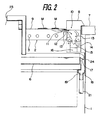
Fig. 2 is an enlarged cross-sectional side view illustrating the suction unit part according to one embodiment of the present invention; -
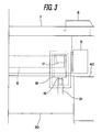
Fig. 3 is an enlarged front view illustrating the suction unit part according to one embodiment of the present invention; and -
Fig. 4 is an enlarged front view illustrating another example of the suction unit according to one embodiment of the present invention. - One embodiment of the present invention will be hereinafter described with reference to the drawings.
- In this embodiment, as shown in
Fig. 1 , anelectric heater unit 2 is provided in an upper part of a casing 1 that is installed on a floor surface. Thisheater unit 2 includes four far infrared sheathedheaters 3 arranged in parallel, and is supplied with power by plugging apower receiving terminal 4 into apower source unit 5 from above. In a lower part of theheater unit 2, awater pan 6 that can be set in and removed from the casing 1 in a lateral direction is installed. On the top of the casing 1, a table 7 having an opening at the center thereof is fixed. A frame-like table plate 8 is detachably mounted in the opening of the table 7, and agrill 9 is placed on a flanged part of the opening in thetable plate 8. - On both sides of the
heater unit 2, as shown inFig. 2 , asuction unit 10 having asuction port 11 for sucking in air below thegrill 9 is provided. The sucked air passes through thesuction unit 10 and flows through aduct 20 and an electricdust collecting unit 30 as shown inFig. 1 . Asirocco fan 40 is arranged downstream of the electricdust collecting unit 30, so that the air that has passed through the electricdust collecting unit 30 is sent to adeodorizer 50. - The structure of the
suction unit 10 will be described in more detail with reference toFig. 2 . In thesuction port 11 of thesuction unit 10 is provided with a horizontalair director plate 12 so that smoke generated from the lower part of the meat M or the like placed on thegrill 9 is sucked in intensively and efficiently. The air sucked in horizontal direction is then oriented into a vertical direction byguide plates 13. At an exit of theguide plates 13, an oilmist collecting chute 14 having a V-shaped cross section is arranged at a predetermined interval with theguide plates 13. The oil mist collecting chute 14A has a hole (not shown) at one location in the longitudinal direction thereof, so that liquefied oil is accumulated in anoil tank 15 that supports the oilmist collecting chute 14. Air that has passed through a gap between theguide plates 13 and the oilmist collecting chute 14 flows through side portions of theoil tank 15 and is sucked into the duct 20 (seeFig. 1 ) through ahole 16. By removing thetable plate 8 from the table 7, thesuction unit 10 can be disassembled and dismounted from the top so that the oilmist collecting chute 14 and theoil tank 15 can be cleaned. - Next, the structure of the
water pan 6 will be described with reference toFig. 2 andFig. 3 . A beak-like oil spout 17 is protruded at the end on one side of thewater pan 6. Liquid that has overflowed from thisoil spout 17 flows into a receptor metal fitting 18 provided in the casing 1. Apipe 19 is formed in the lower part of thereceptor metal fitting 18, so that the liquid is collected through ahose 21 into a wastewater collecting tank 22 (seeFig. 1 ) accommodated in the casing 1. - The electric
dust collecting unit 30 comprises a pre-filter 31 and ahigh voltage collector 32, as shown inFig. 1 . The pre-filter 31 removes large-particle dust in the air sucked in from theduct 20 by thesirocco fan 40 so as to ensure that the successive high-voltage collector 32 operates normally. This pre-filter 31 is made of, for example, a combination of aluminum mesh filter and resin-bonded cotton filter, and can be reused after cleaning off adhered dust. The high-voltage collector 32 includes a plurality of electrodes arranged at predetermined intervals, to which positive and negative voltages are applied to electrify particles in the air passing through the electrodes to be positive or negative so that the particles are attracted to the electrodes. The electricdust collecting unit 30 removes most of the particles in the sucked air. - The
sirocco fan 40 is provided downstream of the electricdust collecting unit 30 to suck in air. By providing thesirocco fan 40 downstream the electricdust collecting unit 30, adhesion of oil components on thesirocco fan 40 is prevented as much as possible. As the strong smell still remains in the air dedusted by the electricdust collecting unit 30, the air is deodorized by thedeodorizer 50 subsequently. - The
deodorizer 50 comprises anoptical catalyst filter 51, anozone generating part 52, anactive charcoal filter 53A, and anozone decomposing catalyst 53B. Theoptical catalyst filter 51 has the functions of oxidizing and decomposing odor, as well as sterilizing, by the strong oxidation effect of active oxygen and hydroxyl radicals that are generated, for example, by irradiating ultraviolet rays to titanium oxide. Theozone generating part 52 generates ozone for deodorization and sterilization. Theactive charcoal filter 53A performs primary deodorization by the effect of the active charcoal. Theozone decomposing catalyst 53B decomposes remains of the ozone generated from theozone generating part 52 after deodorization and sterilization so that the concentration of ozone exhausted in the room does not exceed a standard value. The air deodorized by thedeodorizer 50 is diffused by adiffusion plate 57 and exhausted out of the casing 1. - Ozone generated from the
ozone generating part 52 has a sterilizing effect in addition to the deodorizing effect. Therefore, after the restaurant is closed, by operating thesirocco fan 40 and thedeodorizer 50 alone, the air in the empty restaurant is deodorized and sterilized while circulating. The operating time can suitably be set using a timer or the like. - Here, the
sirocco fan 40 makes noises when it is driven to rotate. A muffler is normally provided downstream of thedeodorizer 50 that is the air exit. However, in this embodiment, the casing of thedeodorizer 50 is constructed in the shape of a muffler comprising an expandinghorn 54, adrum part 55, and a reducinghorn 56, so that the deodorizer also functions as a muffler to make the casing 1 compact. - Next, the operation of this embodiment will be described.
- Power is turned on to start operating the
heater unit 2, the electricdust collecting unit 30, thesirocco fan 40, and thedeodorizer 50. During the cooking, food materials placed on thegrill 9 are heated from below by the far infrared sheathedheaters 3 in theheater unit 2. Smoke generated from the lower side of the heated food materials and air containing a large amount of oil components are sucked in a horizontal direction by the function of theair director plate 12 in thesuction unit 10, oriented from thesuction port 11 into a vertical direction by theguide plates 13, and, as they make contact with the surface of the oilmist collecting chute 14, sucked through thehole 16 into theduct 20. - In the above processes, the high-temperature air containing oil and other components is cooled down on the surfaces of the
guide plates 13 and the oilmist collecting chute 14, whereby the oil mist is liquefied and adheres on the surfaces of theguide plates 13 and the oilmist collecting chute 14. The adhered oil travels on the surface of theguide plates 13 and drips down into the oilmist collecting chute 14. The dropped oil travels along a lengthwise direction of the oilmist collecting chute 14 and through the hole (not shown), and accumulates in theoil tank 15. These processes have a dirt preventing effect for the subsequent connectingduct 20 and the effect of extending the duration of continuously operating the dust collector of the electricdust collecting unit 30 , which is the main unit for removing oil mist that is present forward of the duct. - After oil has been removed to some extent, the air flows through the
duct 20 into the electricdust collecting unit 30, where most of the particle components are collected. However, since odor components still remain at very high concentrations, the air cannot be exhausted to the outside of the casing 1 as it is. Thus, deodorization is performed next using thedeodorizer 50. While theoptical catalyst filter 51 is used in the first step, it is used secondarily because the decomposition and sterilization of odor components by the optical catalyst proceed at a low speed. Deodorization by thedeodorizer 50 is mainly achieved by the odor decomposing effect of ozone generated from theozone generating part 52. The active charcoal of theactive charcoal filter 53A in the next step has an odor adsorption effect and a residual ozone adsorption effect. However, since these absorption effects are decreased when the air temperature is high, this is also used secondarily. Unreacted ozone that remained until the last step is decomposed by theozone decomposing catalyst 53B. - The air deodorized and made harmless as described above is exhausted out of the casing 1 into the interior of the restaurant.
- After cooking for a while, water in the
water pan 6 is decreased by evaporation, and oil and burnt pieces dropping from the food materials accumulate in the pan. Then, clean water is poured slowly into thewater pan 6 using apitcher 23 or the like shown inFig. 2 from the opposite side of theoil spout 17 at one side end of thewater pan 6. Thus, high-temperature wastewater containing a large amount of oil that has a lower specific weight than water overflows from theoil spout 17 and is replaced by the new water. The wastewater that has overflowed from theoil spout 17 flows through thereceptor metal fitting 18 and thepipe 19, and drops into thewastewater collecting tank 22 accommodated in the casing 1. When thewastewater collecting tank 22 become full, or after the restaurant is closed, it is removed to dispose of the wastewater inside. - The
suction unit 10 shown inFig. 2 andFig. 3 is a type that sucks in smoke generated from the food materials from the periphery below the grill 9 (hereinafter referred to as "downside type suction unit"), which is suitable for food materials that are thin and contain a large amount of fat such as sliced meat, which are cooked within a short time and generate much smoke. On the other hand, with the downside type suction unit, the heat that is mainly the radiation heat from the heater unit may not readily be conducted to the center or to the upper part of thick food materials, for example, seafood such as fish, scallop, shelled oyster, and turban shell, or chicken thighs. These food materials generally generate less smoke. Therefore, smoke may be sucked in from the periphery above thegrill 9 so that heated air is well applied to the food materials.Fig. 4 shows such an upside type suction unit. - In an upside
type suction unit 60, asuction port 61 is provided on a periphery above thegrill 9. Thetable plate 8 also has a suction hole 8a at a corresponding part. Inside the upsidetype suction unit 60, aguide plate 62 is provided. Air that has heated the food materials on thegrill 9 is sucked in from the suction hole 8a and thesuction port 61 provided on the periphery above thegrill 9, and oriented into a vertical direction by theguide plate 62. At a bottom exit of theguide plate 62, an oilmist collecting chute 14 having a V-shaped cross section is arranged at a predetermined interval with theguide plate 62. The flow of the air thereafter and the dust collecting and deodorizing processes are the same as of the above-described downsidetype suction unit 10, and the description thereof is omitted. - Accordingly, by selecting the suitable suction type depending on the food materials, it is possible to use either of the suction unit with more weight on the smoke exhaust efficiency or the one with more weight on the heating efficiency. It is also possible to use the same main body of the electric smokeless roaster in one restaurant by setting a suitable one selected from the two types of suction units in accordance with the contents of the ordered menu.
- According to the present invention, oil components and solid components contained in exhaust smoke sucked in by the suction unit are electrically dedusted and deodorized to be returned into a room, thereby requiring no exhaust duct for exhausting smoke into the atmosphere. Therefore, the present invention is applicable as an electric smokeless roaster that can be installed only with electric equipment even in a location without smoke exhaust equipment such as places inside a multi-storied building or a hotel.
Claims (9)
- An electric smokeless roaster comprising:a) a casing (1);b) an electric heater unit (2) installed in an upper part of the casing (1);c) a water pan (6) provided in a lower part of the heater unit (2);d) a grill (9) arranged above the heater unit (2);e) a table (7) mounted on an upper surface of the casing (1) and formed with an opening at a position corresponding to the grill (9);f) a suction unit (10) provided on a periphery of the grill (9) and including a suction port (11) for sucking in air around the grill (9); andg) a suction fan (40) for sucking in the air around the grill (9) via the suction unit (10); whereinh) an electric dust collecting unit (30) for dedusting air sucked in by the suction unit (10) is provided inside the casing (1) between the suction unit (10) and the suction fan (40); the roaster being characterized by:i) a muffler casing comprising an expanding horn (54) is provided on an exhaust side of the suction fan (40), a cross section of an opening on an upstream side of the expanding horn (54) being smaller than a cross section of an opening of a downstream side of the expanding horn (54), a drum part (55) coupled to the expanding horn (54) on the downstream side, and a reducing horn (56) coupled to the drum part (55) on the downstream side, a cross section of an opening on an upstream side of the reducing horn (56) being larger than a cross section of an opening on a downstream side of the reducing horn (56); andj) a deodorizer (50) is provided inside the drum part (55) of the muffler casing to decompose odor components contained in the air dedusted by the electric dust collecting unit (30), said deodorizer (50) comprising an active charcoal filter (53A), an ozone generating part (52), and an ozone decomposing catalyst (53B).
- The electric smokeless roaster according to claim 1, wherein
said suction port of the suction unit (10) is provided on a periphery of the heater unit (2) below the grill (9). - The electric smokeless roaster according to claim 1, wherein
said suction port of the suction unit (10) is provided on a periphery above the grill (9). - The electric smokeless roaster according to claim 1, wherein
a downside type suction unit (10) having a suction port below the grill (9) and an upside type suction unit (10) having a suction port on a periphery above the grill (9) are detachably set in the casing (1) so that they are replaceable. - The electric smokeless roaster according to claim 2, wherein
said suction port of the suction unit (10) includes an air director plate (12) protruded on an upper part on the side of the grill (9). - The electric smokeless roaster according to any one of claims 1 to 5,
wherein
said suction unit (10) comprises a detachable guide plate (13) for guiding air that is sucked in a horizontal direction from the suction port into a vertical direction, a detachable oil mist collecting chute (14) arranged at a predetermined distance with an exit of the guide plate (13), a detachable oil tank (15) for accumulating oil collected in the oil mist collecting chute (14), and a duct (20) for guiding air that has passed through the oil mist collecting chute (14) toward the electric dust collecting unit (30). - The electric smokeless roaster according to any one of claims 1 to 6, wherein
an oil spout (17) is provided at a side end of the water pan (6), so that wastewater that has overflowed from the oil spout (17) is collected in a removable wastewater collecting tank (22) accommodated in the casing (1). - The electric smokeless roaster according to claim 7, wherein
said water pan (6) is detachable from a side of the casing (1). - The electric smokeless roaster according to claim 1, wherein
said deodorizer (50) alone is operable for a predetermined period of time.
Applications Claiming Priority (3)
| Application Number | Priority Date | Filing Date | Title |
|---|---|---|---|
| JP2002169206 | 2002-06-10 | ||
| JP2002169206 | 2002-06-10 | ||
| PCT/JP2003/005057 WO2003103464A1 (en) | 2002-06-10 | 2003-04-22 | Electric smokeless roaster |
Publications (3)
| Publication Number | Publication Date |
|---|---|
| EP1532907A1 EP1532907A1 (en) | 2005-05-25 |
| EP1532907A4 EP1532907A4 (en) | 2007-05-30 |
| EP1532907B1 true EP1532907B1 (en) | 2009-02-25 |
Family
ID=29727719
Family Applications (1)
| Application Number | Title | Priority Date | Filing Date |
|---|---|---|---|
| EP03717667A Expired - Lifetime EP1532907B1 (en) | 2002-06-10 | 2003-04-22 | Electric smokeless roaster |
Country Status (10)
| Country | Link |
|---|---|
| US (1) | US7002110B2 (en) |
| EP (1) | EP1532907B1 (en) |
| JP (1) | JP4346546B2 (en) |
| KR (1) | KR100956804B1 (en) |
| CN (1) | CN100508850C (en) |
| AT (1) | ATE423498T1 (en) |
| AU (1) | AU2003227440A1 (en) |
| DE (1) | DE60326357D1 (en) |
| TW (1) | TWI270360B (en) |
| WO (1) | WO2003103464A1 (en) |
Cited By (1)
| Publication number | Priority date | Publication date | Assignee | Title |
|---|---|---|---|---|
| EP3710755B1 (en) | 2017-11-17 | 2025-04-09 | BSH Hausgeräte GmbH | Fume extractor device for a cooking hob and kitchen furniture with fume extractor device |
Families Citing this family (29)
| Publication number | Priority date | Publication date | Assignee | Title |
|---|---|---|---|---|
| WO2006025659A1 (en) * | 2004-08-06 | 2006-03-09 | Joo-Hwan Hwang | Cooker having deodorization device |
| JP5349747B2 (en) * | 2006-10-19 | 2013-11-20 | 高砂熱学工業株式会社 | Deodorization method |
| US20090061752A1 (en) | 2007-08-28 | 2009-03-05 | Current Energy Controls, Lp | Autonomous Ventilation System |
| US20110146657A1 (en) * | 2009-12-21 | 2011-06-23 | Whirlpool Corporation | Duct free re-circulating downdraft exhaust accessory |
| DE202011005698U1 (en) * | 2011-04-28 | 2011-09-26 | Wilhelm Bruckbauer | Hob with central suction of cooking fumes down |
| CN102913967B (en) * | 2012-08-02 | 2015-06-03 | 重庆迅能节能燃气设备有限公司 | Self-circulation lampblack purification smokeless equipment used for hot pot or barbecue |
| US9897328B2 (en) * | 2013-05-02 | 2018-02-20 | William B. McEvoy | Tabletop cooking assembly |
| KR101468634B1 (en) | 2014-05-02 | 2014-12-03 | 황유성 | Removal System of Volatile Organic Compounds and Odor Using Electrostatic Precipitator and adsorptive low temperature catalyst |
| CN104511224A (en) * | 2014-12-09 | 2015-04-15 | 东莞市蓝鹰环保科技有限公司 | Barbecue smokeless purification device |
| DE102015200642A1 (en) * | 2015-01-16 | 2016-07-21 | Berbel Ablufttechnik Gmbh | Device for extracting exhaust air over a hob |
| EP3133350B1 (en) * | 2015-08-19 | 2020-11-04 | BSH Hausgeräte GmbH | Combination device with cooking hob and extractor device with filter unit |
| EP3133349B1 (en) * | 2015-08-19 | 2019-04-03 | BSH Hausgeräte GmbH | Combination device with cooking hob and extractor device with filter unit |
| US12329314B2 (en) | 2016-06-15 | 2025-06-17 | Koninklijke Philips N.V. | Air-frying cooker |
| CN107960435B (en) * | 2017-12-25 | 2023-03-24 | 宁波明科机电有限公司 | Industrial smoke control frying pan system |
| CN107997384A (en) * | 2017-12-29 | 2018-05-08 | 四川汇健酒店设备有限公司 | Roasting table is rinsed in a kind of oil smoke taste removal purification |
| CN109663440B (en) * | 2018-10-12 | 2024-12-03 | 广州市聚英电器实业有限公司 | A smoking fryer |
| CN109480650B (en) * | 2018-11-21 | 2021-07-20 | 佛山市丽德堡电器有限公司 | Environment-friendly barbecue grill |
| IT201800010578A1 (en) * | 2018-11-26 | 2020-05-26 | Dalpitech S R L | ELECTROSTATIC CONDENSATION EXTRACTOR HOOD |
| CN109394002B (en) * | 2018-12-20 | 2021-11-02 | 宣城市博思特日用品有限公司 | A kind of self-cleaning barbecue and using method |
| KR20220044997A (en) * | 2019-08-07 | 2022-04-12 | 에이엔에이치 이노베이션 인크 | Movable recirculation grill with variable fan drive |
| JP7359433B2 (en) * | 2019-08-26 | 2023-10-11 | 富士工業株式会社 | Oil smoke cleaning device |
| DE102019217111A1 (en) * | 2019-11-06 | 2021-05-06 | Wilhelm Bruckbauer | Odor filter for an extractor device |
| US12320528B2 (en) | 2019-11-27 | 2025-06-03 | Evo America, Llc | Air flow management for cooking system |
| US11236913B2 (en) * | 2019-11-27 | 2022-02-01 | Evo America, Llc | Air flow management for cooking system |
| KR102250904B1 (en) * | 2020-04-20 | 2021-05-11 | 주식회사 모닝아트 | Improved electric roaster with far infrared radiation function |
| US12320527B2 (en) * | 2020-08-25 | 2025-06-03 | Evo America, Llc | Air flow management for cooking system |
| CN112484122B (en) * | 2020-12-07 | 2023-04-07 | 佛山市顺德区美的洗涤电器制造有限公司 | Smoke exhaust component, range hood and integrated stove |
| US11454402B1 (en) | 2021-12-01 | 2022-09-27 | Mcevoy William B | Tabletop cooking assembly |
| KR20240036414A (en) * | 2022-09-13 | 2024-03-20 | 삼성전자주식회사 | Cooking apparatus |
Family Cites Families (33)
| Publication number | Priority date | Publication date | Assignee | Title |
|---|---|---|---|---|
| US3587555A (en) * | 1969-05-13 | 1971-06-28 | Jenn Air Corp | Ventilated range |
| US3665914A (en) * | 1971-06-16 | 1972-05-30 | Victor M Berger | Fire safety device for electric cooking unit |
| JPS5949004B2 (en) | 1980-07-09 | 1984-11-30 | 有限会社峰松電機製作所 | Cooker with smoke evacuation device |
| JPS60816Y2 (en) * | 1981-05-11 | 1985-01-11 | 肥後ステンレス工業株式会社 | Kitchen pottery |
| US4477813A (en) | 1982-08-11 | 1984-10-16 | Ball Corporation | Microstrip antenna system having nonconductively coupled feedline |
| JPS60816A (en) | 1983-06-20 | 1985-01-05 | Hitachi Ltd | air purifier |
| JPH0331242Y2 (en) * | 1985-03-15 | 1991-07-02 | ||
| JPS61234822A (en) * | 1985-04-11 | 1986-10-20 | シンポ株式会社 | Smoke distincting apparatus of roaster |
| JPH0451733Y2 (en) * | 1985-07-05 | 1992-12-04 | ||
| JPS62207417A (en) * | 1986-03-07 | 1987-09-11 | シンポ株式会社 | Non-duct roaster |
| US4750470A (en) * | 1987-03-05 | 1988-06-14 | The Maytag Company | Heater system for a downdraft range |
| JPH053174Y2 (en) * | 1987-07-10 | 1993-01-26 | ||
| JPH0515884Y2 (en) * | 1987-07-25 | 1993-04-26 | ||
| FR2619198B1 (en) * | 1987-08-03 | 1991-04-19 | Alphonse J | DEVICE FOR COOKING GRILLS |
| US4796601A (en) * | 1987-11-12 | 1989-01-10 | Shinpo Kabushiki Kaisha | Smokeless roaster |
| JPH0313932A (en) * | 1989-06-13 | 1991-01-22 | Ricoh Co Ltd | Original reading device |
| JPH0726975Y2 (en) * | 1989-06-27 | 1995-06-21 | シンポ株式会社 | Ductless smokeless roaster |
| JPH0451733A (en) | 1990-06-20 | 1992-02-20 | Nec Corp | Maintenance information management system for communication system |
| JPH04292518A (en) * | 1991-03-20 | 1992-10-16 | Nissan Shatai Co Ltd | Muffling device |
| US5287799A (en) * | 1991-05-23 | 1994-02-22 | Maytag Corporation | Recessed cooktop appliance system |
| JPH058307A (en) | 1991-07-08 | 1993-01-19 | Mitsui Eng & Shipbuild Co Ltd | Optically shaping method |
| JPH058307U (en) * | 1991-07-09 | 1993-02-05 | 博 南條 | Table-type smokeless roaster unit for business use |
| JP3333225B2 (en) * | 1992-01-13 | 2002-10-15 | 株式会社八光電機製作所 | Pizza pie manufacturing equipment |
| JP2717357B2 (en) * | 1993-03-16 | 1998-02-18 | シンポ株式会社 | Smokeless roaster |
| JPH0726975A (en) | 1993-07-09 | 1995-01-27 | Mazda Motor Corp | Rotary piston engine |
| US5619982A (en) * | 1995-07-31 | 1997-04-15 | Maytag Corporation | Method and apparatus for operating a downdraft cooking vapor withdrawal system |
| JPH11107789A (en) * | 1997-10-07 | 1999-04-20 | Makoto Kuwabara | Exhaust controller |
| JPH11324658A (en) * | 1998-05-11 | 1999-11-26 | Suzuki Motor Corp | Engine exhaust muffler device |
| US6146092A (en) * | 1998-07-13 | 2000-11-14 | Ford Motor Company | Centrifugal blower assembly with a diffuser |
| JP2000279325A (en) | 1999-03-31 | 2000-10-10 | Hitachi Hometec Ltd | Cooking device |
| US6455818B1 (en) * | 2001-08-23 | 2002-09-24 | Maytag Corporation | Downdraft filter assembly for a cooking appliance |
| KR200272449Y1 (en) | 2002-01-21 | 2002-04-15 | 박성화 | aaa |
| JP5949004B2 (en) * | 2012-03-16 | 2016-07-06 | セイコーエプソン株式会社 | Sensor unit, exercise measurement system, wearing equipment and exercise equipment |
-
2003
- 2003-04-22 WO PCT/JP2003/005057 patent/WO2003103464A1/en not_active Ceased
- 2003-04-22 AT AT03717667T patent/ATE423498T1/en not_active IP Right Cessation
- 2003-04-22 EP EP03717667A patent/EP1532907B1/en not_active Expired - Lifetime
- 2003-04-22 JP JP2004510594A patent/JP4346546B2/en not_active Expired - Lifetime
- 2003-04-22 AU AU2003227440A patent/AU2003227440A1/en not_active Abandoned
- 2003-04-22 US US10/517,066 patent/US7002110B2/en not_active Expired - Lifetime
- 2003-04-22 CN CNB03813408XA patent/CN100508850C/en not_active Expired - Fee Related
- 2003-04-22 KR KR1020047019994A patent/KR100956804B1/en not_active Expired - Fee Related
- 2003-04-22 DE DE60326357T patent/DE60326357D1/en not_active Expired - Lifetime
- 2003-04-28 TW TW092109916A patent/TWI270360B/en not_active IP Right Cessation
Cited By (1)
| Publication number | Priority date | Publication date | Assignee | Title |
|---|---|---|---|---|
| EP3710755B1 (en) | 2017-11-17 | 2025-04-09 | BSH Hausgeräte GmbH | Fume extractor device for a cooking hob and kitchen furniture with fume extractor device |
Also Published As
| Publication number | Publication date |
|---|---|
| JP4346546B2 (en) | 2009-10-21 |
| JPWO2003103464A1 (en) | 2005-10-06 |
| AU2003227440A1 (en) | 2003-12-22 |
| WO2003103464A1 (en) | 2003-12-18 |
| KR100956804B1 (en) | 2010-05-11 |
| TW200307522A (en) | 2003-12-16 |
| EP1532907A1 (en) | 2005-05-25 |
| CN100508850C (en) | 2009-07-08 |
| ATE423498T1 (en) | 2009-03-15 |
| DE60326357D1 (en) | 2009-04-09 |
| EP1532907A4 (en) | 2007-05-30 |
| CN1658781A (en) | 2005-08-24 |
| KR20050013124A (en) | 2005-02-02 |
| US20050167415A1 (en) | 2005-08-04 |
| TWI270360B (en) | 2007-01-11 |
| AU2003227440A8 (en) | 2003-12-22 |
| US7002110B2 (en) | 2006-02-21 |
Similar Documents
| Publication | Publication Date | Title |
|---|---|---|
| US7002110B2 (en) | Electric smokeless roaster | |
| KR101846046B1 (en) | Using a heat source of grilled dust removal system | |
| JP2008307217A (en) | Smokeless roaster | |
| JP3268229B2 (en) | Exhaust gas purification device | |
| KR102196391B1 (en) | System for collecting exhaust gas generated in restaurants and removing odors from the exhaust gas | |
| US20080121224A1 (en) | Ultra-violet recirculating exhaust hood system | |
| KR100823674B1 (en) | Hood and deodorizer for meat grill | |
| JPH06347047A (en) | Smoke purifying system | |
| CN114729754B (en) | Mobile recirculating grill with variable fan drive | |
| JP2008221047A (en) | Discharged air treatment device | |
| KR20120017836A (en) | Smoke and dust removal device containing burning oil | |
| KR102641936B1 (en) | heating apparatus for food | |
| KR101431508B1 (en) | A duct apparatus for air circulating of automatic | |
| KR100582452B1 (en) | Smoke removal device | |
| JP2002071181A (en) | Cooking exhausting filter, and cooking exhaust hood equipped therewith | |
| KR200367508Y1 (en) | The filtering apparatus for smoke of meet roaster | |
| KR102943008B1 (en) | Device to remove food odors, germs, and bacteria such as cooking fumes in the cafeteria and its method | |
| JP2003001042A (en) | Apparatus for treating exhaust gas produced by cooking, roasting or the like | |
| JP3509739B2 (en) | Cooking device | |
| CN211551722U (en) | Air purification device for barbecue oven | |
| JP2002153385A (en) | Smoke remover | |
| KR100584004B1 (en) | Deodorizer for Roaster | |
| JPH0726975Y2 (en) | Ductless smokeless roaster | |
| KR20250178742A (en) | Air purification filter device containing an air curtain | |
| KR200278860Y1 (en) | Construct of an air cleaner |
Legal Events
| Date | Code | Title | Description |
|---|---|---|---|
| PUAI | Public reference made under article 153(3) epc to a published international application that has entered the european phase |
Free format text: ORIGINAL CODE: 0009012 |
|
| 17P | Request for examination filed |
Effective date: 20041206 |
|
| AK | Designated contracting states |
Kind code of ref document: A1 Designated state(s): AT BE BG CH CY CZ DE DK EE ES FI FR GB GR HU IE IT LI LU MC NL PT RO SE SI SK TR |
|
| AX | Request for extension of the european patent |
Extension state: AL LT LV MK |
|
| DAX | Request for extension of the european patent (deleted) | ||
| A4 | Supplementary search report drawn up and despatched |
Effective date: 20070504 |
|
| 17Q | First examination report despatched |
Effective date: 20070822 |
|
| GRAP | Despatch of communication of intention to grant a patent |
Free format text: ORIGINAL CODE: EPIDOSNIGR1 |
|
| GRAS | Grant fee paid |
Free format text: ORIGINAL CODE: EPIDOSNIGR3 |
|
| GRAA | (expected) grant |
Free format text: ORIGINAL CODE: 0009210 |
|
| RIN1 | Information on inventor provided before grant (corrected) |
Inventor name: HASHIMOTO, KAZUYUKI.KYUSHU ELECTRIC POWER CO.,INC. Inventor name: KAKITSUKA, TOMOKIKYUSHU ELECTRIC POWER CO., INC. Inventor name: SATOU, YOSHIHIROMINEMATSU ELECTRIC CO., LTD. |
|
| AK | Designated contracting states |
Kind code of ref document: B1 Designated state(s): AT BE BG CH CY CZ DE DK EE ES FI FR GB GR HU IE IT LI LU MC NL PT RO SE SI SK TR |
|
| REG | Reference to a national code |
Ref country code: GB Ref legal event code: FG4D |
|
| REG | Reference to a national code |
Ref country code: CH Ref legal event code: EP |
|
| REG | Reference to a national code |
Ref country code: IE Ref legal event code: FG4D |
|
| REF | Corresponds to: |
Ref document number: 60326357 Country of ref document: DE Date of ref document: 20090409 Kind code of ref document: P |
|
| PG25 | Lapsed in a contracting state [announced via postgrant information from national office to epo] |
Ref country code: SI Free format text: LAPSE BECAUSE OF FAILURE TO SUBMIT A TRANSLATION OF THE DESCRIPTION OR TO PAY THE FEE WITHIN THE PRESCRIBED TIME-LIMIT Effective date: 20090225 Ref country code: NL Free format text: LAPSE BECAUSE OF FAILURE TO SUBMIT A TRANSLATION OF THE DESCRIPTION OR TO PAY THE FEE WITHIN THE PRESCRIBED TIME-LIMIT Effective date: 20090225 Ref country code: FI Free format text: LAPSE BECAUSE OF FAILURE TO SUBMIT A TRANSLATION OF THE DESCRIPTION OR TO PAY THE FEE WITHIN THE PRESCRIBED TIME-LIMIT Effective date: 20090225 |
|
| NLV1 | Nl: lapsed or annulled due to failure to fulfill the requirements of art. 29p and 29m of the patents act | ||
| PG25 | Lapsed in a contracting state [announced via postgrant information from national office to epo] |
Ref country code: SE Free format text: LAPSE BECAUSE OF FAILURE TO SUBMIT A TRANSLATION OF THE DESCRIPTION OR TO PAY THE FEE WITHIN THE PRESCRIBED TIME-LIMIT Effective date: 20090525 Ref country code: AT Free format text: LAPSE BECAUSE OF FAILURE TO SUBMIT A TRANSLATION OF THE DESCRIPTION OR TO PAY THE FEE WITHIN THE PRESCRIBED TIME-LIMIT Effective date: 20090225 |
|
| PG25 | Lapsed in a contracting state [announced via postgrant information from national office to epo] |
Ref country code: BE Free format text: LAPSE BECAUSE OF FAILURE TO SUBMIT A TRANSLATION OF THE DESCRIPTION OR TO PAY THE FEE WITHIN THE PRESCRIBED TIME-LIMIT Effective date: 20090225 |
|
| PG25 | Lapsed in a contracting state [announced via postgrant information from national office to epo] |
Ref country code: ES Free format text: LAPSE BECAUSE OF FAILURE TO SUBMIT A TRANSLATION OF THE DESCRIPTION OR TO PAY THE FEE WITHIN THE PRESCRIBED TIME-LIMIT Effective date: 20090605 Ref country code: CZ Free format text: LAPSE BECAUSE OF FAILURE TO SUBMIT A TRANSLATION OF THE DESCRIPTION OR TO PAY THE FEE WITHIN THE PRESCRIBED TIME-LIMIT Effective date: 20090225 Ref country code: EE Free format text: LAPSE BECAUSE OF FAILURE TO SUBMIT A TRANSLATION OF THE DESCRIPTION OR TO PAY THE FEE WITHIN THE PRESCRIBED TIME-LIMIT Effective date: 20090225 Ref country code: PT Free format text: LAPSE BECAUSE OF FAILURE TO SUBMIT A TRANSLATION OF THE DESCRIPTION OR TO PAY THE FEE WITHIN THE PRESCRIBED TIME-LIMIT Effective date: 20090812 Ref country code: DK Free format text: LAPSE BECAUSE OF FAILURE TO SUBMIT A TRANSLATION OF THE DESCRIPTION OR TO PAY THE FEE WITHIN THE PRESCRIBED TIME-LIMIT Effective date: 20090225 |
|
| PG25 | Lapsed in a contracting state [announced via postgrant information from national office to epo] |
Ref country code: RO Free format text: LAPSE BECAUSE OF FAILURE TO SUBMIT A TRANSLATION OF THE DESCRIPTION OR TO PAY THE FEE WITHIN THE PRESCRIBED TIME-LIMIT Effective date: 20090225 Ref country code: SK Free format text: LAPSE BECAUSE OF FAILURE TO SUBMIT A TRANSLATION OF THE DESCRIPTION OR TO PAY THE FEE WITHIN THE PRESCRIBED TIME-LIMIT Effective date: 20090225 |
|
| REG | Reference to a national code |
Ref country code: CH Ref legal event code: PL |
|
| PLBE | No opposition filed within time limit |
Free format text: ORIGINAL CODE: 0009261 |
|
| STAA | Information on the status of an ep patent application or granted ep patent |
Free format text: STATUS: NO OPPOSITION FILED WITHIN TIME LIMIT |
|
| PG25 | Lapsed in a contracting state [announced via postgrant information from national office to epo] |
Ref country code: LI Free format text: LAPSE BECAUSE OF NON-PAYMENT OF DUE FEES Effective date: 20090430 Ref country code: BG Free format text: LAPSE BECAUSE OF FAILURE TO SUBMIT A TRANSLATION OF THE DESCRIPTION OR TO PAY THE FEE WITHIN THE PRESCRIBED TIME-LIMIT Effective date: 20090525 Ref country code: CH Free format text: LAPSE BECAUSE OF NON-PAYMENT OF DUE FEES Effective date: 20090430 |
|
| 26N | No opposition filed |
Effective date: 20091126 |
|
| PG25 | Lapsed in a contracting state [announced via postgrant information from national office to epo] |
Ref country code: MC Free format text: LAPSE BECAUSE OF NON-PAYMENT OF DUE FEES Effective date: 20090430 Ref country code: IE Free format text: LAPSE BECAUSE OF NON-PAYMENT OF DUE FEES Effective date: 20090422 |
|
| PG25 | Lapsed in a contracting state [announced via postgrant information from national office to epo] |
Ref country code: GR Free format text: LAPSE BECAUSE OF FAILURE TO SUBMIT A TRANSLATION OF THE DESCRIPTION OR TO PAY THE FEE WITHIN THE PRESCRIBED TIME-LIMIT Effective date: 20090526 |
|
| PG25 | Lapsed in a contracting state [announced via postgrant information from national office to epo] |
Ref country code: IT Free format text: LAPSE BECAUSE OF FAILURE TO SUBMIT A TRANSLATION OF THE DESCRIPTION OR TO PAY THE FEE WITHIN THE PRESCRIBED TIME-LIMIT Effective date: 20090225 |
|
| PG25 | Lapsed in a contracting state [announced via postgrant information from national office to epo] |
Ref country code: LU Free format text: LAPSE BECAUSE OF NON-PAYMENT OF DUE FEES Effective date: 20090422 |
|
| PG25 | Lapsed in a contracting state [announced via postgrant information from national office to epo] |
Ref country code: HU Free format text: LAPSE BECAUSE OF FAILURE TO SUBMIT A TRANSLATION OF THE DESCRIPTION OR TO PAY THE FEE WITHIN THE PRESCRIBED TIME-LIMIT Effective date: 20090826 |
|
| PG25 | Lapsed in a contracting state [announced via postgrant information from national office to epo] |
Ref country code: TR Free format text: LAPSE BECAUSE OF FAILURE TO SUBMIT A TRANSLATION OF THE DESCRIPTION OR TO PAY THE FEE WITHIN THE PRESCRIBED TIME-LIMIT Effective date: 20090225 |
|
| PG25 | Lapsed in a contracting state [announced via postgrant information from national office to epo] |
Ref country code: CY Free format text: LAPSE BECAUSE OF FAILURE TO SUBMIT A TRANSLATION OF THE DESCRIPTION OR TO PAY THE FEE WITHIN THE PRESCRIBED TIME-LIMIT Effective date: 20090225 |
|
| REG | Reference to a national code |
Ref country code: DE Ref legal event code: R082 Ref document number: 60326357 Country of ref document: DE Representative=s name: SAMSON & PARTNER, PATENTANWAELTE, DE |
|
| REG | Reference to a national code |
Ref country code: DE Ref legal event code: R082 Ref document number: 60326357 Country of ref document: DE Representative=s name: SAMSON & PARTNER, PATENTANWAELTE, DE Effective date: 20130715 Ref country code: DE Ref legal event code: R081 Ref document number: 60326357 Country of ref document: DE Owner name: TAIKO ENTERPRISES CORP., GARDENA, US Free format text: FORMER OWNER: KYUSHU ELECTRIC POWER CO., INC., MINEMATSU EELCTRIC MACHINE CO.,, , JP Effective date: 20130715 Ref country code: DE Ref legal event code: R081 Ref document number: 60326357 Country of ref document: DE Owner name: TAIKO ENTERPRISES CORP., GARDENA, US Free format text: FORMER OWNER: MINEMATSU ELECTRIC MACHINE CO.,, TAIKO ENTERPRISES CORP., , US Effective date: 20130812 Ref country code: DE Ref legal event code: R082 Ref document number: 60326357 Country of ref document: DE Representative=s name: SAMSON & PARTNER PATENTANWAELTE MBB, DE Effective date: 20130812 Ref country code: DE Ref legal event code: R082 Ref document number: 60326357 Country of ref document: DE Representative=s name: SAMSON & PARTNER PATENTANWAELTE MBB, DE Effective date: 20130715 Ref country code: DE Ref legal event code: R081 Ref document number: 60326357 Country of ref document: DE Owner name: TAIKO ENTERPRISES CORP., GARDENA, US Free format text: FORMER OWNER: MINEMATSU EELCTRIC MACHINE CO.,, TAIKO ENTERPRISES CORP., , US Effective date: 20130730 Ref country code: DE Ref legal event code: R082 Ref document number: 60326357 Country of ref document: DE Representative=s name: SAMSON & PARTNER PATENTANWAELTE MBB, DE Effective date: 20130730 Ref country code: DE Ref legal event code: R081 Ref document number: 60326357 Country of ref document: DE Owner name: TAIKO ENTERPRISES CORP., GARDENA, US Free format text: FORMER OWNERS: KYUSHU ELECTRIC POWER CO., INC., FUKUOKA, JP; MINEMATSU EELCTRIC MACHINE CO., LTD., FUKUOKA, JP Effective date: 20130715 Ref country code: DE Ref legal event code: R081 Ref document number: 60326357 Country of ref document: DE Owner name: MINEMATSU ELECTRIC MACHINE CO.,LTD, JP Free format text: FORMER OWNERS: MINEMATSU ELECTRIC MACHINE CO.,LTD., FUKUOKA, JP; TAIKO ENTERPRISES CORP., GARDENA, CALIF., US Effective date: 20130812 Ref country code: DE Ref legal event code: R081 Ref document number: 60326357 Country of ref document: DE Owner name: TAIKO ENTERPRISES CORP., GARDENA, US Free format text: FORMER OWNERS: MINEMATSU ELECTRIC MACHINE CO.,LTD., FUKUOKA, JP; TAIKO ENTERPRISES CORP., GARDENA, CALIF., US Effective date: 20130812 Ref country code: DE Ref legal event code: R081 Ref document number: 60326357 Country of ref document: DE Owner name: MINEMATSU ELECTRIC MACHINE CO.,LTD, JP Free format text: FORMER OWNERS: KYUSHU ELECTRIC POWER CO., INC., FUKUOKA, JP; MINEMATSU EELCTRIC MACHINE CO., LTD., FUKUOKA, JP Effective date: 20130715 Ref country code: DE Ref legal event code: R081 Ref document number: 60326357 Country of ref document: DE Owner name: MINEMATSU ELECTRIC MACHINE CO.,LTD., JP Free format text: FORMER OWNER: KYUSHU ELECTRIC POWER CO., INC., MINEMATSU EELCTRIC MACHINE CO.,, , JP Effective date: 20130715 Ref country code: DE Ref legal event code: R081 Ref document number: 60326357 Country of ref document: DE Owner name: TAIKO ENTERPRISES CORP., US Free format text: FORMER OWNER: MINEMATSU EELCTRIC MACHINE CO.,, TAIKO ENTERPRISES CORP., , US Effective date: 20130730 Ref country code: DE Ref legal event code: R082 Ref document number: 60326357 Country of ref document: DE Representative=s name: SAMSON & PARTNER, PATENTANWAELTE, DE Effective date: 20130730 Ref country code: DE Ref legal event code: R081 Ref document number: 60326357 Country of ref document: DE Owner name: TAIKO ENTERPRISES CORP., US Free format text: FORMER OWNER: KYUSHU ELECTRIC POWER CO., INC., MINEMATSU EELCTRIC MACHINE CO.,, , JP Effective date: 20130715 Ref country code: DE Ref legal event code: R081 Ref document number: 60326357 Country of ref document: DE Owner name: MINEMATSU ELECTRIC MACHINE CO.,LTD., JP Free format text: FORMER OWNER: MINEMATSU EELCTRIC MACHINE CO.,, TAIKO ENTERPRISES CORP., , US Effective date: 20130730 Ref country code: DE Ref legal event code: R081 Ref document number: 60326357 Country of ref document: DE Owner name: MINEMATSU ELECTRIC MACHINE CO.,LTD, JP Free format text: FORMER OWNER: MINEMATSU EELCTRIC MACHINE CO.,, TAIKO ENTERPRISES CORP., , US Effective date: 20130730 Ref country code: DE Ref legal event code: R082 Ref document number: 60326357 Country of ref document: DE Representative=s name: SAMSON & PARTNER, PATENTANWAELTE, DE Effective date: 20130812 Ref country code: DE Ref legal event code: R081 Ref document number: 60326357 Country of ref document: DE Owner name: MINEMATSU ELECTRIC MACHINE CO.,LTD, JP Free format text: FORMER OWNER: KYUSHU ELECTRIC POWER CO., INC., MINEMATSU EELCTRIC MACHINE CO.,, , JP Effective date: 20130715 Ref country code: DE Ref legal event code: R081 Ref document number: 60326357 Country of ref document: DE Owner name: MINEMATSU ELECTRIC MACHINE CO.,LTD, JP Free format text: FORMER OWNER: MINEMATSU ELECTRIC MACHINE CO.,, TAIKO ENTERPRISES CORP., , US Effective date: 20130812 Ref country code: DE Ref legal event code: R081 Ref document number: 60326357 Country of ref document: DE Owner name: TAIKO ENTERPRISES CORP., US Free format text: FORMER OWNER: MINEMATSU ELECTRIC MACHINE CO.,, TAIKO ENTERPRISES CORP., , US Effective date: 20130812 Ref country code: DE Ref legal event code: R081 Ref document number: 60326357 Country of ref document: DE Owner name: TAIKO ENTERPRISES CORP., GARDENA, US Free format text: FORMER OWNERS: MINEMATSU EELCTRIC MACHINE CO., LTD., FUKUOKA, JP; TAIKO ENTERPRISES CORP., GARDENA, CALIF., US Effective date: 20130730 Ref country code: DE Ref legal event code: R081 Ref document number: 60326357 Country of ref document: DE Owner name: MINEMATSU ELECTRIC MACHINE CO.,LTD, JP Free format text: FORMER OWNERS: MINEMATSU EELCTRIC MACHINE CO., LTD., FUKUOKA, JP; TAIKO ENTERPRISES CORP., GARDENA, CALIF., US Effective date: 20130730 |
|
| REG | Reference to a national code |
Ref country code: GB Ref legal event code: 732E Free format text: REGISTERED BETWEEN 20130919 AND 20130925 |
|
| REG | Reference to a national code |
Ref country code: FR Ref legal event code: TQ Owner name: TAIKO ENTERPRISES CORP., US Effective date: 20131230 Ref country code: FR Ref legal event code: TQ Owner name: MINEMATSU ELECTRIC MACHINE CO.,LTD., JP Effective date: 20131230 Ref country code: FR Ref legal event code: TP Owner name: MINEMATSU ELECTRIC MACHINE CO.,LTD., JP Effective date: 20131230 Ref country code: FR Ref legal event code: TP Owner name: TAIKO ENTERPRISES CORP., US Effective date: 20131230 |
|
| REG | Reference to a national code |
Ref country code: FR Ref legal event code: PLFP Year of fee payment: 14 |
|
| REG | Reference to a national code |
Ref country code: FR Ref legal event code: PLFP Year of fee payment: 15 |
|
| REG | Reference to a national code |
Ref country code: FR Ref legal event code: PLFP Year of fee payment: 16 |
|
| PGFP | Annual fee paid to national office [announced via postgrant information from national office to epo] |
Ref country code: DE Payment date: 20210420 Year of fee payment: 19 Ref country code: FR Payment date: 20210423 Year of fee payment: 19 |
|
| PGFP | Annual fee paid to national office [announced via postgrant information from national office to epo] |
Ref country code: GB Payment date: 20210421 Year of fee payment: 19 |
|
| REG | Reference to a national code |
Ref country code: DE Ref legal event code: R119 Ref document number: 60326357 Country of ref document: DE |
|
| GBPC | Gb: european patent ceased through non-payment of renewal fee |
Effective date: 20220422 |
|
| PG25 | Lapsed in a contracting state [announced via postgrant information from national office to epo] |
Ref country code: GB Free format text: LAPSE BECAUSE OF NON-PAYMENT OF DUE FEES Effective date: 20220422 Ref country code: FR Free format text: LAPSE BECAUSE OF NON-PAYMENT OF DUE FEES Effective date: 20220430 Ref country code: DE Free format text: LAPSE BECAUSE OF NON-PAYMENT OF DUE FEES Effective date: 20221103 |