EP1532237B1 - Zellkultureinsatz - Google Patents
Zellkultureinsatz Download PDFInfo
- Publication number
- EP1532237B1 EP1532237B1 EP03790846A EP03790846A EP1532237B1 EP 1532237 B1 EP1532237 B1 EP 1532237B1 EP 03790846 A EP03790846 A EP 03790846A EP 03790846 A EP03790846 A EP 03790846A EP 1532237 B1 EP1532237 B1 EP 1532237B1
- Authority
- EP
- European Patent Office
- Prior art keywords
- cell culture
- insert
- wall
- culture insert
- well
- Prior art date
- Legal status (The legal status is an assumption and is not a legal conclusion. Google has not performed a legal analysis and makes no representation as to the accuracy of the status listed.)
- Expired - Lifetime
Links
Images


Classifications
-
- B—PERFORMING OPERATIONS; TRANSPORTING
- B01—PHYSICAL OR CHEMICAL PROCESSES OR APPARATUS IN GENERAL
- B01L—CHEMICAL OR PHYSICAL LABORATORY APPARATUS FOR GENERAL USE
- B01L3/00—Containers or dishes for laboratory use, e.g. laboratory glassware; Droppers
- B01L3/50—Containers for the purpose of retaining a material to be analysed, e.g. test tubes
- B01L3/508—Rigid containers without fluid transport within
-
- C—CHEMISTRY; METALLURGY
- C12—BIOCHEMISTRY; BEER; SPIRITS; WINE; VINEGAR; MICROBIOLOGY; ENZYMOLOGY; MUTATION OR GENETIC ENGINEERING
- C12M—APPARATUS FOR ENZYMOLOGY OR MICROBIOLOGY; APPARATUS FOR CULTURING MICROORGANISMS FOR PRODUCING BIOMASS, FOR GROWING CELLS OR FOR OBTAINING FERMENTATION OR METABOLIC PRODUCTS, i.e. BIOREACTORS OR FERMENTERS
- C12M23/00—Constructional details, e.g. recesses, hinges
- C12M23/02—Form or structure of the vessel
- C12M23/12—Well or multiwell plates
-
- C—CHEMISTRY; METALLURGY
- C12—BIOCHEMISTRY; BEER; SPIRITS; WINE; VINEGAR; MICROBIOLOGY; ENZYMOLOGY; MUTATION OR GENETIC ENGINEERING
- C12M—APPARATUS FOR ENZYMOLOGY OR MICROBIOLOGY; APPARATUS FOR CULTURING MICROORGANISMS FOR PRODUCING BIOMASS, FOR GROWING CELLS OR FOR OBTAINING FERMENTATION OR METABOLIC PRODUCTS, i.e. BIOREACTORS OR FERMENTERS
- C12M25/00—Means for supporting, enclosing or fixing the microorganisms, e.g. immunocoatings
- C12M25/02—Membranes; Filters
- C12M25/04—Membranes; Filters in combination with well or multiwell plates, i.e. culture inserts
-
- B—PERFORMING OPERATIONS; TRANSPORTING
- B01—PHYSICAL OR CHEMICAL PROCESSES OR APPARATUS IN GENERAL
- B01L—CHEMICAL OR PHYSICAL LABORATORY APPARATUS FOR GENERAL USE
- B01L2200/00—Solutions for specific problems relating to chemical or physical laboratory apparatus
- B01L2200/02—Adapting objects or devices to another
- B01L2200/025—Align devices or objects to ensure defined positions relative to each other
-
- B—PERFORMING OPERATIONS; TRANSPORTING
- B01—PHYSICAL OR CHEMICAL PROCESSES OR APPARATUS IN GENERAL
- B01L—CHEMICAL OR PHYSICAL LABORATORY APPARATUS FOR GENERAL USE
- B01L2200/00—Solutions for specific problems relating to chemical or physical laboratory apparatus
- B01L2200/02—Adapting objects or devices to another
- B01L2200/026—Fluid interfacing between devices or objects, e.g. connectors, inlet details
-
- B—PERFORMING OPERATIONS; TRANSPORTING
- B01—PHYSICAL OR CHEMICAL PROCESSES OR APPARATUS IN GENERAL
- B01L—CHEMICAL OR PHYSICAL LABORATORY APPARATUS FOR GENERAL USE
- B01L2200/00—Solutions for specific problems relating to chemical or physical laboratory apparatus
- B01L2200/06—Fluid handling related problems
- B01L2200/0642—Filling fluids into wells by specific techniques
-
- B—PERFORMING OPERATIONS; TRANSPORTING
- B01—PHYSICAL OR CHEMICAL PROCESSES OR APPARATUS IN GENERAL
- B01L—CHEMICAL OR PHYSICAL LABORATORY APPARATUS FOR GENERAL USE
- B01L2300/00—Additional constructional details
- B01L2300/06—Auxiliary integrated devices, integrated components
- B01L2300/0681—Filter
Definitions
- the invention relates to a cell culture insert with a cup-shaped insert wall with a membrane filter bottom and with above distributed circumferentially protruding support arms and with lateral spacers for vertical and horizontal orientation in a well with a nutrient fluid in a cell culture plate.
- Cell culture inserts should, in order to be able to work comfortably with them, have a large filling opening. Also, the lower cross-section with the membrane should be sufficiently large to allow a good fluid exchange between the cup contents and the Wellinhalt. It is also convenient to mount the cell culture inserts in the well so as not to have feet that interfere with cell growth at the bottom of the insert. In addition to the accessibility of the cell culture insert through the filling opening and the accessibility of the corrugated tray for pipettes is important.
- cell culture inserts in cup form for example from the patent US 4,871,674 and US 5,578,492 known, which are mounted in a well and allow access to the cell culture insert and the well.
- the cell inserts described here have a symmetrical construction and, when suspended, have only small feed windows around the inserts for the introduction of pipettes into the well.
- the cell culture insert can be placed in an upper position to increase the loading window for insertion of a pipette.
- the cell culture insert is applied to the wall of the well, whereby the cells are damaged in the well.
- a cell culture insert which carries at an upper flange a conically narrowing to 45 degrees conical up to a cylindrical culture space support arm assembly, wherein between the support arms are recesses which a Provide pipette accessibility.
- the culture space is considerably narrowed to about 1 ⁇ 4 of the diameter of the receiving space.
- the known cell culture inserts are either made of completely colorless transparent material or of the same monochrome plastic as the cell culture plate with the wells. This results in a poor distinction between the well and the cell culture insert, making manual and automatic work difficult.
- This object is achieved by the fact that the spacers are distributed on the circumference of the cell culture insert and formed to the side so different lengths that result in a large feed window and several smaller windows.
- the cup-shaped cell culture insert hangs on support arms on the upper edge of the well and is positioned asymmetrically over spacers of different lengths. In the process, a feed window is formed between the longest spacers, into which pipettes can be conveniently inserted.
- Three spacers distributed circumferentially over more than half the circumference are minimally required to position the cell culture insert in the well's opening.
- the largest feed window is when one of the three spacers is shorter than the other two.
- the shortest spacer determines a minimum distance between the cell culture insert and the wall of the well so that capillary spaces of cells between the cell culture insert and the corrugated wall are avoided, so that no liquid rises there.
- a short spacer and two equally long spacer webs are distributed circumferentially evenly distributed on the cup.
- the spacer webs which assume asymmetric positioning therein upon insertion of the cell culture insert into the well, are advantageously tapered downwardly.
- the support arms ensure that the cell culture insert hangs in the well at a defined height.
- the shortest spacer ensures that there is a minimum distance between the walls of the cell culture insert and the well.
- At least one wall recess formed in the top wall between the long spacer webs provides a further improved pipette accessibility.
- the depth of the recess is for example 20% of the application height.
- the lower edge of the wall recess has a sufficient safety margin to the nutrient solution level.
- the Ausappelungskante runs to avoid critical bending stresses to the support arms towards rounded divergent upwards.
- the insert wall has a relatively large diameter in the culture space, since it is provided only with Ausformschrägen which outside about 1.5 degrees and inside about 3.3 degrees. The free membrane diameter is thereby larger than the radius of the well. If Wandaüs Principle 11, are introduced between all support arms, the tweezer access to the support arms is substantially improved in addition to the pipette accessibility.
- the cell culture insert can be pushed up with a pipette, allowing it to slide out of the well along the oblique spacers. After removing the pipette, the cell culture insert slides reliably back into the well along the spacers.
- the high closed design of the cell culture insert avoids contamination between the inside and the outside of the cell culture insert.
- the cell culture insert in the well For handling the cell culture insert in the well, it can be easily grasped, inserted and also lifted out again by means of tweezers on one of the long support arms.
- Polyester or polycarbonate capillary membranes have the advantage of precisely adjustable porosity and transparency.
- the cell culture insert is made of a colored plastic which provides a visible contrast to the material of the well.
- a transparent colored plastic is used.
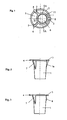
- a cell culture insert 1 first embodiment is shown in plan view, as in a round opening in the well 2, a cell culture insert 1 is held eccentrically to the opening. It is held by three support arms 3, 4, wherein the support arm 3 is made shorter than the other two. This results in a large feed window 5, into which a pipette can be easily inserted, and two smaller windows 5A.
- the opening 6 of the cell culture insert is well accessible from above.
- the support arms 3, 4 are arranged offset by 120 degrees.
- the eccentricity between the axis of the well and the insert is more than 1.3 mm, for example 4 mm. This is achieved by different spacer webs, which are arranged under the support arms 3, 4.
- Fig. 2 shows a side view of the cup-shaped cell culture insert 1. At it long triangular spacer bars 7 are tapered laterally down and another shorter spacer bar 7 a attached. At the top of the insert wall 11, the support arms 3, 4 are formed, of which the support arm 3 is shorter, which belongs to the shorter spacer web 7a.
- Fig. 3 shows a side view of the cup-shaped cell culture insert 1 in a modified form. At him the triangular spacer bars 7 and another spacer 8 are mounted in knob shape.
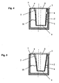
- Fig. 4 shows a section through the cylindrical well 2 with hinged cell culture insert 1.
- the support arms 3, 4 are on top of the well 2 and determine the altitude of the cell culture set 1.
- the feed window 5 is located between the long support arms 4.
- the cell culture insert 1 has the opening 6 at the top and the membrane 9 at the bottom. The distance between the walls is so great at the level height P of the liquid level 10 that there is no capillary action.
- Fig. 5 shows the same cut as Fig. 4 , with the difference that the distance between the walls of the insert 1 and the well 2 at the level of the liquid level 10 is determined by the relatively larger slope of the cell culture insert 1, which in the example is about 7 degrees.
- Fig. 6 shows in perspective another embodiment of a cell culture insert 1 A, in which the insert wall 11 from above between the support arms 3, 4 each have a wall recess 12 which is formed rounded towards the support arms.
- the recess depth T is about 20% of the insertion height H, so that the lower edge 13 of the WandausappelInstitut 12 has a sufficient level distance H to the usual liquid level 10.
- Figure 7 shows an axial cross section through the execution Fig. 6 , One recognizes there the size ratio of the recess depth T to the insert height H, which is about five times as large. Also, the normal level P of the nutrient fluid 10 is shown, which is about 1/3 of the insertion height H above the diaphragm 9.
- the insert wall 11 is outside with a Ausformschräge tapered downwards from about 1.5 degrees and tapered inwardly at about 3.3 degrees, so that the top wall thickness WO increases downwards from 1 mm to a bottom wall thickness WU of 1.5 mm, which provides a secure welding edge for the bottom creates the membrane 9 and above more peripheral space.
- Fig. 8 shows the top view Fig. 7 , Dash-dotted lines the inner wall W of the well is indicated, whose corrugation radius R is smaller than the membrane diameter D.
- the eccentricity of the insert 1A to the inner wall W is about 1.5 mm in the example.
- the corrugation radius R is 10 - 12 mm and the usable diameter D of the diaphragm 9 11 - 13 mm.
- the insert wall 11 is above about 15 - 17 mm wide.
- the spacers 7, 8 provide by their different lateral extent an eccentricity of the insert 1A in the well 2 of 1.3 - 1.7 mm.
Landscapes
- Health & Medical Sciences (AREA)
- Chemical & Material Sciences (AREA)
- Bioinformatics & Cheminformatics (AREA)
- Organic Chemistry (AREA)
- Zoology (AREA)
- Wood Science & Technology (AREA)
- Life Sciences & Earth Sciences (AREA)
- Engineering & Computer Science (AREA)
- General Health & Medical Sciences (AREA)
- Clinical Laboratory Science (AREA)
- Biomedical Technology (AREA)
- Biotechnology (AREA)
- Microbiology (AREA)
- Sustainable Development (AREA)
- Biochemistry (AREA)
- General Engineering & Computer Science (AREA)
- Genetics & Genomics (AREA)
- Chemical Kinetics & Catalysis (AREA)
- Hematology (AREA)
- Analytical Chemistry (AREA)
- Immunology (AREA)
- Apparatus Associated With Microorganisms And Enzymes (AREA)
Abstract
Description
- Die Erfindung betrifft einen Zellkultureinsatz mit einer becherförmigen Einsatzwand mit einem Membranfilterboden und mit oben umfangsmäßig verteilten herausstehenden Tragearmen und mit seitlichen Abstandhaltern für eine vertikale und horizontale Orientierung in einem Well mit einer Nährflüssigkeit in einer Zellkulturplatte.
- Zellkultureinsätze sollen, um mit ihnen bequem arbeiten zu können, eine große Einfüllöffnung besitzen. Auch der untere Querschnitt mit der Membran soll ausreichend groß sein, um einen guten Flüssigkeitsaustausch zwischen dem Becherinhalt und dem Wellinhalt zu erlauben. Auch ist es günstig, die Zellkultureinsätze in das Well einzuhängen, um an dem unteren Rand des Einsatzes keine das Zellwachstum störenden Füße zu haben. Neben der Zugänglichkeit des Zellkultureinsatzes durch die Einfüllöffnung ist auch die Zugänglichkeit des Wellbodens für Pipetten wichtig.
- So sind Zellkultureinsätze in Becherform, beispielsweise aus der Patentschrift
US 4,871,674 undUS 5,578,492 , bekannt, die in ein Well eingehängt sind und den Zugang zum Zellkultureinsatz und zum Well erlauben. Die hier beschriebenen Zelleinsätze sind symmetrisch aufgebaut und besitzen im eingehängten Zustand rund um die Einsätze nur kleine Beschickungsfenster für das Einführen von Pipetten in das Well. - In der Patentschrift
US 4,871,674 ist beschrieben, dass der Zellkultureinsatz in eine obere Stellung gebracht werden kann, um das Beschickungsfenster zum Einführen einer Pipette zu vergrößern. Dabei liegt der Zellkultureinsatz an der Wand des Wells an, wodurch die Zellen im Well geschädigt werden. - Weiterhin ist aus der
US 5,272,083 ein Zellkultureinsatz bekannt, der an einem oberen Flansch eine sich unter 45 Grad konisch bis zu einem zylindrischen Kulturraum verengende Tragarmanordnung trägt, wobei zwischen den Tragarmen Ausnehmungen sind, die eine Pipettenzugänglichkeit erbringen. Der Kulturraum ist dabei erheblich, auf ca. ¼ des Durchmessers des Aufnahmeraums, eingeengt. - Die bekannten Zellkultureinsätze sind entweder aus völlig farblosen transparentem Material oder aus dem gleichen einfarbigen Kunststoff hergestellt wie die Zellkulturplatte mit den Wells. Dadurch ergibt sich eine schlechte Unterscheidbarkeit zwischen dem Well und dem Zellkultureinsatz, womit das manuelle und das automatische Arbeiten erschwert ist.
- Es ist Aufgabe der Erfindung, einen verbesserten Zellkultureinsatz mit ausreichend großer Membranfläche anzugeben, bei dem das Beschickungsfenster für das Well wesentlich größer ist und bei dem keine Bewegung des Einsatzes erforderlich ist, um Pipetten in das Beschickungsfenster einzuführen.
- Gelöst wird diese Aufgabe dadurch, dass die Abstandshalter auf dem Umfang des Zellkultureinsatz so verteilt und zur Seite so unterschiedlich lang ausgebildet sind, dass sich ein großes Beschickungsfenster und mehrere kleinere Fenster ergeben.
- Vorteilhafte Ausgestaltungen der Erfindung sind in den Unteransprüchen angegeben.
- Der becherförmige Zellkultureinsatz hängt an Tragarmen auf dem oberen Rand des Wells und ist über unterschiedlich lange Abstandhalter asymmetrisch positioniert. Dabei bildet sich zwischen den längsten Abstandhaltern ein Beschickungsfenster aus, in das bequem Pipetten eingerührt werden können.
- Drei Abstandhalter, die umfangsmäßig auf mehr als den halben Umfang verteilt sind, sind minimal erforderlich, um den Zellkultureinsatz in der Öffnung des Wells definiert zu positionieren. Das größte Beschickungsfenster ergibt sich, wenn einer der drei Abstandhalter kürzer als die beiden anderen ist.
- Günstig in dieser Anordnung ist, dass der kürzeste Abstandhalter einen Mindestabstand zwischen dem Zellkultureinsatz und der Wand des Wells so bestimmt, dass kapillare Engräume von Zellen zwischen dem Zellkultureinsatz und der Wellwand vermieden werden, so dass keine Flüssigkeit dort aufsteigt.
- Vorteilhaft sind ein kurzer Abstandhalter und zwei gleich lange Abstandsstege umfangsmäßig gleich verteilt am Becher angeordnet. Die Abstandstege, die beim Einführen des Zellkultureinsatzes in das Well eine asymmetrische Positionierung darin übernehmen, sind vorteilhafterweise nach unten verjüngt. Die Tragearme sorgen dafür, dass der Zellkultureinsatz in einer definierten Höhe im Well hängt. Der kürzeste Abstandhalter sorgt dafür, dass ein Mindestabstand zwischen den Wänden vom Zellkultureinsatz und dem Well eingehalten wird.
- In einer besonders vorteilhaften Ausführung erbringt mindestens eine in die Einsatzwand obenendig zwischen den langen Abstandsstegen ausgebildete Wandausnehmung eine noch weiter verbesserte Pipettenzugänglichkeit. Die Tiefe der Ausnehmung beträgt beispielsweise 20% der Einsatzhöhe. Die Unterkante der Wandausnehmung weist einen ausreichenden Sicherheitsabstand zum Nährlösungspegel auf. Die Ausnehmungskante verläuft zur Vermeidung von kritischen Biegespannungen zu den Tragarmen hin abgerundet divergierend nach oben. Die Einsatzwand weist einen relativ großen Durchmesser im Kulturraum auf, da sie nur mit Ausformschrägen versehen ist, die außen etwa 1,5 Grad und innen etwa 3,3 Grad betragen. Der freie Membrandurchmesser ist dadurch größer als der Radius des Wells. Wenn zwischen allen Tragarmen Wandaüsnehmungen eingebracht sind, ist außer der Pipettenzugänglichkeit auch der Pinzettenzugriff zu den Tragarmen wesentlich verbessert.
- Trotz der exzentrischen Aufhängung des Zellkultureinsatzes im Well bleibt für die automatische optische Auswertung der Zellkulturplatten mit den hier beschriebenen Zellkultureinsätzen ein genügend großes Beobachtungsfenster von z.B. 3 mm Durchmesser über der Mitte der Wells erhalten.
- Wird ein größeres Beschickungsfenster benötigt, kann der Zellkultureinsatz mit einer Pipette nach oben geschoben werden, wobei es an den schrägen Abstandhaltern entlang ein Stück aus dem Well gleiten kann. Nach dem Entfernen der Pipette gleitet der Zellkultureinsatz an den Abstandhaltern entlang zuverlässig in das Well zurück.
- Durch die hohe geschlossene Bauart des Zellkultureinsatzes wird eine Kontamination zwischen der Innen- und der Außenseite des Zellkultureinsatzes vermieden.
- Für die Handhabung des Zellkultureinsatzes im Well lässt er sich mittels einer Pinzette an einem der langen Tragarme leicht erfassen, einsetzen und auch wieder herausheben.
- Alle für Zellkultureinsätze bekannte Membranen können verwendet werden; Kapillarenmembranen aus Polyester oder Polycarbonat haben den Vorzug einer genau einstellbaren Porosität und Transparenz.
- Vorteilhafterweise wird der Zellkultureinsatz aus einem eingefärbten Kunststoff hergestellt, der einen sichtbaren Kontrast zu dem Material des Wells darstellt. Damit ist die Erkennbarkeit der Einfüllöffnung verbessert. Vorzugsweise kommt ein transparenter farbiger Kunststoff zum Einsatz.
- Eine Ausführung der Erfindung ist in den Figuren beispielhaft beschrieben.
-
Fig. 1 zeigt eine Draufsicht auf einen Zellkultureinsatz erster Ausführung im Well, -
Fig. 2 zeigt eine Ansicht des Zellkultureinsatzes von der Seite mit drei Abstandstegen, -
Fig. 3 zeigt eine Ansicht des Zellkultureinsatzes von der Seite mit Abstandstegen und Abstandshalter, -
Fig. 4 zeigt eine Schnittdarstellung des Well mit Zellkultureinsatz mit Abstandhalter, -
Fig. 5 zeigt eine Schnittdarstellung des Well mit Zellkultureinsatz mit schräger Wandung; -
Fig. 6 zeigt eine zweite Ausführung des Einsatzes in Perspektive; -
Fig. 7 zeigt dazu einen axialen Schnitt A - A; -
Fig. 8 zeigt dazu eine Draufsicht. - In
Fig. 1 ist ein Zellkultureinsatz 1 erster Ausführung in der Draufsicht dargestellt, wie in einer runden Öffnung im Well 2 ein Zellkultureinsatz 1 außermittig zur Öffnung gehalten ist. Er wird von drei Tragearmen 3, 4 gehalten, wobei der Tragearm 3 kürzer als die beiden anderen ausgeführt ist. Dadurch ergibt sich ein großes Beschickungsfenster 5, in das eine Pipette leicht eingeführt werden kann, sowie zwei kleinere Fenster 5A. Auch die Öffnung 6 des Zellkultureinsatzes ist gut von oben zugänglich. Die Tragearme 3, 4 sind jeweils um 120 Grad versetzt angeordnet. Die Exzentrizität zwischen der Achse des Well und der des Einsatzes beträgt mehr als 1,3 mm, z.B. 4 mm. Diese wird durch unterschiedliche Abstandsstege, die unter den Tragarmen 3, 4 angeordnet sind, erreicht. -
Fig. 2 zeigt eine Seitenansicht des becherförmigen Zellkultureinsatzes 1. An ihm sind lange dreieckförmigen Abstandstege 7 seitlich nach unten verjüngt und ein weiterer kürzerer Abstandsteg 7a angebracht. Oben sind an der Einsatzwand 11 die Tragearme 3, 4 ausgeformt, von denen der Tragearm 3 kürzer ist, der zu dem kürzeren Abstandssteg 7a gehört. -
Fig. 3 zeigt eine Seitenansicht des becherförmigen Zellkultureinsatzes 1 in abgewandelter Form. An ihm sind die dreieckförmigen Abstandstege 7 und ein weiterer Abstandhalter 8 in Noppenform angebracht. -
Fig. 4 zeigt einen Schnitt durch das zylindrische Well 2 mit eingehängtem Zellkultureinsatz 1. Die Tragearme 3, 4 liegen oben auf dem Well 2 auf und bestimmen die Höhenlage des Zellkultweinsatzes 1. Über die Abstandstege 7 und dem Abstandhalter 8 wird der Abstand zwischen den Wänden definiert gehalten. Das Beschickungsfenster 5 liegt zwischen den langen Tragearmen 4. Der Zellkultureinsatz 1 besitzt oben die Öffnung 6 und unten die Membran 9. Der Abstand zwischen den Wänden ist in der Pegelhöhe P des Flüssigkeitsspiegels 10 so groß, dass sich keine Kapillarwirkung ergibt. -
Fig. 5 zeigt den gleichen Schnitt wieFig. 4 , mit dem Unterschied, dass der Abstand zwischen den Wänden des Einsatzes 1 und des Wells 2 in Höhe des Flüssigkeitsspiegels 10 durch die relativ größere Schräge des Zellkultureinsatzes 1 bestimmt wird, die im Beispiel ca. 7 Grad beträgt. -
Fig. 6 zeigt perspektivisch eine weitere Ausführungsform eines Zellkultureinsatzes 1 A, bei dem die Einsatzwand 11 von oben zwischen den Tragarmen 3, 4 jeweils eine Wandausnehmung 12 aufweist, die zu den Tragarmen hin abgerundet ausgebildet ist. Die Ausnehmungstiefe T beträgt etwa 20% der Einsatzhöhe H, so dass die Unterkante 13 der Wandausnehmungen 12 einen ausreichenden Pegelabstand H zum üblichen Flüssigkeitsspiegel 10 aufweist. -
Fig.7 zeigt einen axialen Querschnitt durch die AusführungFig. 6 . Man erkennt dort das Größenverhältnis der Ausnehmungstiefe T zur Einsatzhöhe H, die etwa fünf mal so groß ist. Auch der Normalpegelstand P der Nährflüssigkeit 10 ist dargestellt, der etwa 1/3 der Einsatzhöhe H über der Membran 9 liegt. Die Einsatzwand 11 ist außen mit einer Ausformschräge von ca. 1,5 Grad nach unten konisch verjüngt und innen mit etwa 3,3 Grad verjüngt, so dass die obere Wandstärke WO nach unten von 1 mm auf eine untere Wandstärke WU von 1,5 mm zunimmt, was unten einen sicheren Schweißrand für die Membran 9 und oben mehr umlaufenden Freiraum schafft. -
Fig. 8 zeigt die Draufsicht zuFig. 7 . Strichpunktiert ist die Innenwand W des Wells angedeutet, deren Wellradius R kleiner als der Membrandurchmesser D ist. Die Exzentrizität des Einsatzes 1A zur Wellinnenwand W beträgt etwa 1,5 mm im Beispiel. - Beispielsweise beträgt der Wellradius R 10 - 12 mm und der nutzbare Durchmesser D der Membran 9 11 - 13 mm. Die Einsatzwand 11 ist oben etwa 15 - 17 mm weit. Die Abstandshalter 7, 8 erbringen durch ihre unterschiedliche seitliche Erstreckung eine Exzentrizität des Einsatzes 1A im Well 2 von 1,3 - 1,7 mm.
-
- 1
- 1A Zellkultureinsatz
- 2
- Well
- 3
- kurzer Tragearm
- 4
- langer Tragearm
- 5
- Beschickungsfenster groß
- 5a
- Beschickungsfenster klein
- 6
- Öffnung des Zellkultureinsatzes
- 7
- Langer Abstandsteg
- 7a
- Kurzer Abstandsteg
- 8
- Abstandhalter
- 9
- Membran
- 10
- Flüssigkeitsspiegel
- 11
- Einsatzwand
- 12
- Wandausnehmung
- 13
- Unterkante der Wandausnehmung
- A
- Pegelabstand zur Unterkante
- D
- Membrandurchmesser
- H
- Einsatzhöhe
- N
- Nährflüssigkeit
- P
- Pegelhöhe
- R
- Wellradius
- T
- Ausnehmungstiefe
- W
- Wellinnenwand
- WO
- obere Wandstärke
- WU
- untere Wandstärke
Claims (15)
- Zellkultureinsatz (1) mit einer becherförmigen Einsatzwand (11) mit einem Membranfilterboden (9), einem oberen Rand und mit daran umfangsmäßig verteilten herausstehenden Tragearmen (3, 4) und mit seitlichen Abstandhaltern (7, 8) für eine vertikale und horizontale Orientierung in einem Well (2) mit einer Nährflüssigkeit (N) in einer Zellkulturplatte, dadurch gekennzeichnet, dass
die Abstandshalter (7, 8) auf dem Umfang des Zellkultureinsatz (1) verteilt und zur Seite unterschiedlich lang ausgebildet sind, wobei ein Abstandshalter (8) der kürzeste ist, so dass sich bei einer Aufhängung im Well (2) ein großes Beschickungsfenster (5) und mehrere kleinere Fenster (5A) ergeben. - Zellkultureinsatz nach Anspruch 1, dadurch gekennzeichnet, dass mindestens zwei der Abstandhalter (7) als nach unten verjüngte dreieckige Abstandstege ausgeführt sind.
- Zellkultureinsatz nach Anspruch 1, dadurch gekennzeichnet, dass der kürzeste Abstandhalter (8) einen Mindestabstand zwischen der Einsatzwand (11) des Zellkultureinsatzes (1) und Innenwand (W) des Wells (2) bestimmt, der ein kapillares Aufsteigen der Nährflüssigkeit (N) verhindert.
- Zellkultureinsatz nach Anspruch 1, dadurch gekennzeichnet, dass der Abstand zwischen der Einsatzwand (11) des Zellkultureinsatz (1) und einer Innenwand (W) des Wells (2) durch eine nach unten verjüngte Form der Einsatzwand (11) bestimmt ist.
- Zellkultureinsatz nach Anspruch 1, dadurch gekennzeichnet, dass der Zellkultureinsatz (1) an drei Tragearmen (3, 4) in das Well (2) exzentrisch eingehängt gehalten ist.
- Zellkultureinsatz nach Anspruch 5, dadurch gekennzeichnet, dass die Tragarme (3,4) anschließend über den Abstandhaltern (7, 8) und umfangsmäßig je um 120 Grad versetzt angeordnet sind.
- Zellkultureinsatz nach Anspruch 1, dadurch gekennzeichnet, dass die Einsatzwand (11) zwischen mindestens den zwei längeren Tragearmen (4) oben eine Wandausnehmung (12) mit einer Unterkante (13) aufweist, die beabstandet über einem normalen Pegelstand (10) der Nährstoffflüssigkeit (N) liegt.
- Zellkultureinsatz nach Anspruch 7, dadurch gekennzeichnet, dass die Unterkante (13) der Wandausnehmung (12) zu den Tragarmen (3, 4) bogenformig verläuft.
- Zellkultureinsatz nach Anspruch 7, dadurch gekennzeichnet, dass die Wandausnehmung eine Tiefe (T) hat, die etwa 20% einer Einsatzhöhe (H) des Einsatzes (1, 1A) beträgt.
- Zellkultureinsatz nach Anspruch 1, dadurch gekennzeichnet, dass seine Einsatzwand (11) membranseitig eine größere Wandstärke (WU) aufweist als obenseitig.
- Zellkultureinsatz nach Anspruch 10, dadurch gekennzeichnet, dass seine Einsatzwand (11) außen von oben nach unten verjüngt mit einer Ausformschräge von etwa 1,5 Grad ausgebildet ist und die Einsatzwand (11) innen eine Schräge von 3,3 Grad aufweist.
- Zellkultureinsatz nach Anspruch 11, dadurch gekennzeichnet, dass die Membran (9) einen größeren Durchmesser (D) hat als einen inneren Wellradius (R) des umgebenden Wells (2).
- Zellkultureinsatz nach Anspruch 11, dadurch gekennzeichnet, dass der Wellradius (R) 10-12 mm beträgt, der Durchmesser (D) der Membran (9) 11 - 13 mm beträgt, die Einsatzwand oben außen 15 - 17 mm weit ist und die Abstandshalter (7, 8) eine Exzentrizität von über 1,3 mm des Zellkultureinsatzes (1) zum Well (2) gewährleisten.
- Zellkultureinsatz nach Anspruch 1, dadurch gekennzeichnet, dass er aus eingefärbtem Material besteht.
- Zellkultureinsatz nach Anspruch 14, dadurch gekennzeichnet, dass er aus transparentem Material besteht.
Applications Claiming Priority (3)
| Application Number | Priority Date | Filing Date | Title |
|---|---|---|---|
| DE10240787 | 2002-08-30 | ||
| DE10240787A DE10240787B4 (de) | 2002-08-30 | 2002-08-30 | Zellkultureinsatz |
| PCT/EP2003/008527 WO2004020571A2 (de) | 2002-08-30 | 2003-08-01 | Zellkultureinsatz |
Publications (2)
| Publication Number | Publication Date |
|---|---|
| EP1532237A2 EP1532237A2 (de) | 2005-05-25 |
| EP1532237B1 true EP1532237B1 (de) | 2011-03-02 |
Family
ID=31724310
Family Applications (1)
| Application Number | Title | Priority Date | Filing Date |
|---|---|---|---|
| EP03790846A Expired - Lifetime EP1532237B1 (de) | 2002-08-30 | 2003-08-01 | Zellkultureinsatz |
Country Status (5)
| Country | Link |
|---|---|
| US (1) | US7598076B2 (de) |
| EP (1) | EP1532237B1 (de) |
| AU (1) | AU2003260351A1 (de) |
| DE (2) | DE10240787B4 (de) |
| WO (1) | WO2004020571A2 (de) |
Cited By (2)
| Publication number | Priority date | Publication date | Assignee | Title |
|---|---|---|---|---|
| DE202017003978U1 (de) | 2016-08-18 | 2017-08-28 | Brand Gmbh + Co Kg | Zellkultureinsatz und Vorrichtung zum Kultivieren von Zellen |
| DE102017007169A1 (de) | 2016-08-18 | 2018-02-22 | Brand Gmbh + Co Kg | Zellkultureinsatz und Vorrichtung zum Kultivieren von Zellen |
Families Citing this family (23)
| Publication number | Priority date | Publication date | Assignee | Title |
|---|---|---|---|---|
| WO2006131123A2 (en) * | 2005-06-10 | 2006-12-14 | Nunc A/S | Culture insert carrier, culture insert and culture insert system |
| US20080076170A1 (en) * | 2006-09-27 | 2008-03-27 | Tuija Annala | Cell culture insert and cell culture vessel |
| PT103906A (pt) * | 2007-12-20 | 2009-08-31 | Ass For The Advancement Of Tis | Sistemas dinâmicos de cultura de células em suportes tridimensionais |
| FR2942239B1 (fr) * | 2009-02-18 | 2013-07-26 | Oreal | Dispositif de culture cellulaire ou tissulaire et ensemble associe |
| FR2942240B1 (fr) * | 2009-02-18 | 2011-03-18 | Oreal | Dispositif de culture cellulaire ou tissulaire avec adaptateur et ensemble de culture cellulaire ou tissulaire associe |
| DE102009022352A1 (de) | 2009-05-15 | 2010-11-18 | Fraunhofer-Gesellschaft zur Förderung der angewandten Forschung e.V. | Ablöseverfahren für adhärente Zellen |
| DE102009022354B4 (de) | 2009-05-15 | 2015-05-07 | Fraunhofer-Gesellschaft zur Förderung der angewandten Forschung e.V. | Bioreaktorsystem |
| DE202011003049U1 (de) | 2011-02-22 | 2011-04-28 | Sabeu Kunststoffwerk Northeim Gmbh | Einsatz für Zellkulturen |
| US9186669B2 (en) | 2012-02-10 | 2015-11-17 | Applied Biophysics, Inc. | Filter device for facilitating characterizing behavior of cells |
| EP2653531A1 (de) * | 2012-04-18 | 2013-10-23 | Oxyphen AG | Kulturanordnung |
| EP2902475B1 (de) * | 2012-09-26 | 2021-09-22 | Hitachi, Ltd. | Zellkulturgefäss und zellkulturvorrichtung |
| KR101422345B1 (ko) * | 2012-10-19 | 2014-07-22 | 한국생명공학연구원 | 이중구조 세포배양용기 |
| CN103992949B (zh) * | 2014-05-29 | 2016-08-24 | 中国科学院合肥物质科学研究院 | 一种纳米材料诱导dna损伤的检测装置及快速检测方法 |
| DE102015202402B3 (de) * | 2015-02-11 | 2015-08-27 | Fraunhofer-Gesellschaft zur Förderung der angewandten Forschung e.V. | Zellkulturplatte |
| CN212881367U (zh) * | 2016-12-08 | 2021-04-06 | 反应分析公司 | 样品小瓶组件和过滤器插入件 |
| SG11201909419XA (en) | 2017-04-10 | 2019-11-28 | TheWell Bioscience | Hydrogel for cell culture and biomedical applications |
| FR3067040B1 (fr) * | 2017-06-02 | 2021-06-11 | Oreal | Dispositif destine a recevoir un depot de materiau par impression, ensemble et procede associes |
| US11273447B2 (en) * | 2019-01-11 | 2022-03-15 | Purdue Research Foundation | Collapsible basket arrays, collapsible cellular arrays therefor, and methods of use |
| JP7265243B2 (ja) * | 2019-01-15 | 2023-04-26 | ネッパジーン株式会社 | セルカルチャーインサート |
| US11732232B2 (en) | 2020-08-14 | 2023-08-22 | Korea Research Institute Of Bioscience And Biotechnology | Biomimetic cell culture apparatus and cell culture system comprising the same |
| USD946167S1 (en) * | 2020-10-16 | 2022-03-15 | Emd Millipore Corporation | Cell culture hanging insert |
| DE102021132560A1 (de) * | 2021-12-09 | 2023-06-15 | Sabeu Gmbh & Co. Kg | Probenvorrichtung für Zellkulturen |
| DE102023109953B3 (de) | 2023-04-20 | 2024-06-20 | Laser nanoFab GmbH | Scaffold-Halter |
Family Cites Families (10)
| Publication number | Priority date | Publication date | Assignee | Title |
|---|---|---|---|---|
| JPH051280Y2 (de) * | 1987-10-12 | 1993-01-13 | ||
| US5272083A (en) * | 1990-10-10 | 1993-12-21 | Costar Corporation | Culture device and method of use having a detachable cell or tissue growth surface |
| CA2055966C (en) * | 1990-12-19 | 1995-08-01 | Oresta Natalia Fedun | Cell culture insert |
| US5650323A (en) * | 1991-06-26 | 1997-07-22 | Costar Corporation | System for growing and manipulating tissue cultures using 96-well format equipment |
| AU658079B2 (en) * | 1992-09-28 | 1995-03-30 | Becton Dickinson & Company | Cell culture insert |
| US5468638A (en) * | 1992-09-28 | 1995-11-21 | Becton, Dickinson And Company | Cell culture insert |
| US5366893A (en) * | 1993-01-13 | 1994-11-22 | Becton, Dickinson And Company | Culture vessel |
| US5534227A (en) * | 1995-06-05 | 1996-07-09 | Becton, Dickinson And Company | Thermoform dish insert |
| US5710043A (en) * | 1995-09-25 | 1998-01-20 | Becton Dickinson And Company | In vitro cell culture assembly |
| US5801055A (en) * | 1997-09-10 | 1998-09-01 | Becton Dickinson And Company | Multi-well culture dish assembly |
-
2002
- 2002-08-30 DE DE10240787A patent/DE10240787B4/de not_active Expired - Fee Related
-
2003
- 2003-08-01 EP EP03790846A patent/EP1532237B1/de not_active Expired - Lifetime
- 2003-08-01 WO PCT/EP2003/008527 patent/WO2004020571A2/de not_active Ceased
- 2003-08-01 DE DE50313510T patent/DE50313510D1/de not_active Expired - Lifetime
- 2003-08-01 US US10/522,544 patent/US7598076B2/en not_active Expired - Lifetime
- 2003-08-01 AU AU2003260351A patent/AU2003260351A1/en not_active Abandoned
Cited By (3)
| Publication number | Priority date | Publication date | Assignee | Title |
|---|---|---|---|---|
| DE202017003978U1 (de) | 2016-08-18 | 2017-08-28 | Brand Gmbh + Co Kg | Zellkultureinsatz und Vorrichtung zum Kultivieren von Zellen |
| DE102017007169A1 (de) | 2016-08-18 | 2018-02-22 | Brand Gmbh + Co Kg | Zellkultureinsatz und Vorrichtung zum Kultivieren von Zellen |
| WO2018033253A1 (de) | 2016-08-18 | 2018-02-22 | Brand Gmbh + Co Kg | Zellkultureinsatz und vorrichtung zum kultivieren von zellen |
Also Published As
| Publication number | Publication date |
|---|---|
| WO2004020571A3 (de) | 2004-11-04 |
| US20060051857A1 (en) | 2006-03-09 |
| WO2004020571A2 (de) | 2004-03-11 |
| DE10240787B4 (de) | 2004-07-22 |
| AU2003260351A1 (en) | 2004-03-19 |
| DE10240787A1 (de) | 2004-03-18 |
| EP1532237A2 (de) | 2005-05-25 |
| US7598076B2 (en) | 2009-10-06 |
| DE50313510D1 (de) | 2011-04-14 |
| AU2003260351A8 (en) | 2004-03-19 |
Similar Documents
| Publication | Publication Date | Title |
|---|---|---|
| WO2004020571A2 (de) | Zellkultureinsatz | |
| DE69615655T2 (de) | Biologische analytische vorrichtung mit verbesserter verhinderung von kontamination | |
| DE602004010474T2 (de) | Behälter zur Kultivierung von Geweben | |
| DE69101611T2 (de) | Gerät zur Behandlung biologischer Proben. | |
| DE60317603T2 (de) | Mikroplatte mit Schutzunterplatte | |
| DE60224673T2 (de) | Kulturflasche | |
| DE69635398T2 (de) | Thermoformierter Behälter für Zellkultureinsatz | |
| DE69706313T2 (de) | Verfahren und vorrichtung, reagenzien zu transferieren und zu kombinieren | |
| DE69319983T2 (de) | Zellkultureinsatz | |
| DE2904597C2 (de) | Küvetteneinsatz | |
| DE4405375C2 (de) | Mikrotiterplatte | |
| DE60012817T2 (de) | Verbesserte Titrationsplatten | |
| DE60113515T2 (de) | Apparat zum Einsammeln oder Freisetzen magnetischer Partikel | |
| DE3618884C2 (de) | Biochemische Testplattenanordnung | |
| DE2835362A1 (de) | Vorrichtung zur konditionierung einer fluessigkeit in analysezellen | |
| DE202017003978U1 (de) | Zellkultureinsatz und Vorrichtung zum Kultivieren von Zellen | |
| EP2711080B1 (de) | Hohlnadel für einen probenpipettor | |
| DE102010010975B4 (de) | Objektträgerhalter | |
| CH628255A5 (en) | Interconnected set of vessels with a plurality of reaction vessels, and retaining appliance for at least one such interconnected set | |
| DE69928630T2 (de) | Einwegvorrichtung für eine Thorax-Drainage anschliessbar an eine Saugeinheit | |
| EP3430462B1 (de) | Vorrichtung zum einsetzen in ein bildgebendes system | |
| DE3631066A1 (de) | Objekttraeger fuer nasse oder feuchte biologische praeparate, z. b. blut | |
| DE102017007169A1 (de) | Zellkultureinsatz und Vorrichtung zum Kultivieren von Zellen | |
| EP1397201B2 (de) | Reaktionsgefäss zur herstellung von proben | |
| DE2823476C2 (de) | Mehrzweck-Trennkammer für die Dünnschichtchromatographie |
Legal Events
| Date | Code | Title | Description |
|---|---|---|---|
| PUAI | Public reference made under article 153(3) epc to a published international application that has entered the european phase |
Free format text: ORIGINAL CODE: 0009012 |
|
| 17P | Request for examination filed |
Effective date: 20050129 |
|
| AK | Designated contracting states |
Kind code of ref document: A2 Designated state(s): AT BE BG CH CY CZ DE DK EE ES FI FR GB GR HU IE IT LI LU MC NL PT RO SE SI SK TR |
|
| AX | Request for extension of the european patent |
Extension state: AL LT LV MK |
|
| DAX | Request for extension of the european patent (deleted) | ||
| RBV | Designated contracting states (corrected) |
Designated state(s): DE FR GB |
|
| 17Q | First examination report despatched |
Effective date: 20081010 |
|
| RAP1 | Party data changed (applicant data changed or rights of an application transferred) |
Owner name: OXYPHEN AG |
|
| GRAP | Despatch of communication of intention to grant a patent |
Free format text: ORIGINAL CODE: EPIDOSNIGR1 |
|
| RAP1 | Party data changed (applicant data changed or rights of an application transferred) |
Owner name: OXYPHEN AG |
|
| GRAS | Grant fee paid |
Free format text: ORIGINAL CODE: EPIDOSNIGR3 |
|
| GRAA | (expected) grant |
Free format text: ORIGINAL CODE: 0009210 |
|
| AK | Designated contracting states |
Kind code of ref document: B1 Designated state(s): DE FR GB |
|
| REG | Reference to a national code |
Ref country code: GB Ref legal event code: FG4D Free format text: NOT ENGLISH |
|
| REF | Corresponds to: |
Ref document number: 50313510 Country of ref document: DE Date of ref document: 20110414 Kind code of ref document: P |
|
| REG | Reference to a national code |
Ref country code: DE Ref legal event code: R096 Ref document number: 50313510 Country of ref document: DE Effective date: 20110414 |
|
| PLBE | No opposition filed within time limit |
Free format text: ORIGINAL CODE: 0009261 |
|
| STAA | Information on the status of an ep patent application or granted ep patent |
Free format text: STATUS: NO OPPOSITION FILED WITHIN TIME LIMIT |
|
| 26N | No opposition filed |
Effective date: 20111205 |
|
| REG | Reference to a national code |
Ref country code: DE Ref legal event code: R097 Ref document number: 50313510 Country of ref document: DE Effective date: 20111205 |
|
| REG | Reference to a national code |
Ref country code: DE Ref legal event code: R082 Ref document number: 50313510 Country of ref document: DE Representative=s name: TARVENKORN & WICKORD PATENTANWAELTE PARTNERSCH, DE |
|
| REG | Reference to a national code |
Ref country code: FR Ref legal event code: PLFP Year of fee payment: 14 |
|
| REG | Reference to a national code |
Ref country code: FR Ref legal event code: PLFP Year of fee payment: 15 |
|
| REG | Reference to a national code |
Ref country code: FR Ref legal event code: PLFP Year of fee payment: 16 |
|
| REG | Reference to a national code |
Ref country code: DE Ref legal event code: R082 Ref document number: 50313510 Country of ref document: DE |
|
| PGFP | Annual fee paid to national office [announced via postgrant information from national office to epo] |
Ref country code: GB Payment date: 20220829 Year of fee payment: 20 Ref country code: DE Payment date: 20220829 Year of fee payment: 20 |
|
| PGFP | Annual fee paid to national office [announced via postgrant information from national office to epo] |
Ref country code: FR Payment date: 20220825 Year of fee payment: 20 |
|
| P01 | Opt-out of the competence of the unified patent court (upc) registered |
Effective date: 20230526 |
|
| REG | Reference to a national code |
Ref country code: DE Ref legal event code: R071 Ref document number: 50313510 Country of ref document: DE |
|
| REG | Reference to a national code |
Ref country code: GB Ref legal event code: PE20 Expiry date: 20230731 |
|
| PG25 | Lapsed in a contracting state [announced via postgrant information from national office to epo] |
Ref country code: GB Free format text: LAPSE BECAUSE OF EXPIRATION OF PROTECTION Effective date: 20230731 |