EP1532039B1 - Karosserie für einen kraftwagen - Google Patents
Karosserie für einen kraftwagen Download PDFInfo
- Publication number
- EP1532039B1 EP1532039B1 EP03794854A EP03794854A EP1532039B1 EP 1532039 B1 EP1532039 B1 EP 1532039B1 EP 03794854 A EP03794854 A EP 03794854A EP 03794854 A EP03794854 A EP 03794854A EP 1532039 B1 EP1532039 B1 EP 1532039B1
- Authority
- EP
- European Patent Office
- Prior art keywords
- module
- roof
- bearing
- pillars
- lid
- Prior art date
- Legal status (The legal status is an assumption and is not a legal conclusion. Google has not performed a legal analysis and makes no representation as to the accuracy of the status listed.)
- Expired - Lifetime
Links
- 238000003860 storage Methods 0.000 description 4
- 239000002131 composite material Substances 0.000 description 3
- 238000010276 construction Methods 0.000 description 3
- 238000005304 joining Methods 0.000 description 3
- 239000000853 adhesive Substances 0.000 description 2
- 230000001070 adhesive effect Effects 0.000 description 2
- 238000004519 manufacturing process Methods 0.000 description 2
- 239000002184 metal Substances 0.000 description 2
- 150000001875 compounds Chemical class 0.000 description 1
- 230000000694 effects Effects 0.000 description 1
- 230000002349 favourable effect Effects 0.000 description 1
- 238000005058 metal casting Methods 0.000 description 1
Images


Classifications
-
- B—PERFORMING OPERATIONS; TRANSPORTING
- B62—LAND VEHICLES FOR TRAVELLING OTHERWISE THAN ON RAILS
- B62D—MOTOR VEHICLES; TRAILERS
- B62D65/00—Designing, manufacturing, e.g. assembling, facilitating disassembly, or structurally modifying motor vehicles or trailers, not otherwise provided for
-
- B—PERFORMING OPERATIONS; TRANSPORTING
- B62—LAND VEHICLES FOR TRAVELLING OTHERWISE THAN ON RAILS
- B62D—MOTOR VEHICLES; TRAILERS
- B62D25/00—Superstructure or monocoque structure sub-units; Parts or details thereof not otherwise provided for
- B62D25/04—Door pillars ; windshield pillars
-
- B—PERFORMING OPERATIONS; TRANSPORTING
- B62—LAND VEHICLES FOR TRAVELLING OTHERWISE THAN ON RAILS
- B62D—MOTOR VEHICLES; TRAILERS
- B62D25/00—Superstructure or monocoque structure sub-units; Parts or details thereof not otherwise provided for
- B62D25/06—Fixed roofs
-
- B—PERFORMING OPERATIONS; TRANSPORTING
- B62—LAND VEHICLES FOR TRAVELLING OTHERWISE THAN ON RAILS
- B62D—MOTOR VEHICLES; TRAILERS
- B62D65/00—Designing, manufacturing, e.g. assembling, facilitating disassembly, or structurally modifying motor vehicles or trailers, not otherwise provided for
- B62D65/02—Joining sub-units or components to, or positioning sub-units or components with respect to, body shell or other sub-units or components
- B62D65/06—Joining sub-units or components to, or positioning sub-units or components with respect to, body shell or other sub-units or components the sub-units or components being doors, windows, openable roofs, lids, bonnets, or weather strips or seals therefor
Definitions
- the invention relates to a body for a motor vehicle specified in the preamble of claim 1. Art.
- From US-A-6 334 252 is a support structure with an attached Roof module to be known as known, to which a adjacent hood mounted adjacent to the roof.
- the bearing arrangement The hood is arranged directly on the roof module and can thus already before putting the roof module on the Support structure are preassembled on the roof module.
- the roof pillars are on support surfaces of the Door pillars and the bearing brackets are on support surfaces of the structural component supported the support structure.
- the invention is based on the object, a body of to create the aforementioned type, in which the bearing brackets and the bearing assembly improves supported on the support structure are.
- the bearing arrangement of the lid or the hood directly on the Roof module arranged so that the lid on relatively simple Way and under the mediation of a high quality impression in an exact position opposite the adjacent roof module can be positioned. Manufacturing tolerances, when assembling the roof module with the support structure arise, thus have no effect on the position the lid opposite the adjacent roof module.
- a technically particularly favorable bearing arrangement comprises in each case a fixed to the associated roof pillar of the roof module Bearings, over which a positionally accurate and stable Storage of the lid to the roof module are guaranteed can.
- a particularly stable support of the bearing is by means of Bearing consoles given, which in extension of the roof pillars are arranged at the lower ends.
- the warehouse consoles rest preferably on support surfaces of the support structure, see above that both a good support of the bearing brackets with the Storage as well as the entire roof module on the roof pillars is reached.
- Fig.1 is a perspective exploded view a Trag Gent.10 shown a motor vehicle body, the from several large-format, to be described in more detail below Submodules is composed.
- the submodules of Support structure 10 are in the embodiment shown here each of a plurality of assembled sheet metal parts produced; however, the sub-modules may as well also in other constructions, for example as so-called spaceframe, as plastic parts, metal castings, as components in So-called sandwich construction or the like. Prefabricated.
- the individual modules are in particular over Glued joints, welded joints or the like. Assembled. Likewise, others are common compounds like Screw connections or the like. Conceivable.
- a base module 12 of the support structure 10 essentially comprises a body floor 14, the side of side rails 16 is limited. Towards the front, the basic module 12 extends to column sections 18 of front wall columns 20, which of the respective associated front ends of the lateral side members 16 project upwards.
- the body floor 14 of the basic module 12 ends at a considerable distance behind the front end of the basic module 12 or behind the column sections 18 the front wall pillars 20. Rear ends the base module 12 behind rear wheel arches 22, above which wall portions 24 the respective rear side wall are arranged.
- the Basic module 12 is already before joining with the others Submodules equipped as far as possible.
- a front module 26 is connected, which belongs to the front crumple zone of the motor vehicle and crash stable on the base module 12 is supported.
- the front module 26 a front end portion 28 of the body floor 14, which extends between lateral side member sections 30 of Vorbaumoduls 26 extends. Ends to the front the front end portion 28 of the body floor 14 at a front end wall 32 of the passenger compartment, extending from the front End portion 28 of the body floor 14 to about at height the side wall edge of the support structure 10 extends. Laterally becomes the end wall 32 of column sections 34 of the front wall columns 20 limited, which of the lateral side member sections 30 of the Vorbaumoduls 34 protrude upward. At the front end of Vorbaumoduls 34 are front side members 36th and front side wall portions 38 recognizable. Forward joins the front module 26 a front module 40, which is partially shown in Figure 2 and for example includes the front bumper.
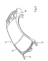
- roof module 42 On the base module 12 and the front end module 26 is one in sync with Figure 3 recognizable roof module 42 can be placed, which here lateral A-pillars 44, in the region of the roof 43rd lateral roof pillars 46, and C pillars 48 includes.
- the lower Ends of the A-pillars 44 and the C-pillars 48 are above each a cross member 50 connected together.
- the A-pillars 44 are based on composite support structure 10 in the further explained manner both on the base module 12th and on the front module 26 from.
- At the back are the lower ones Ends of the C-pillars 48 at their respective upper end the wall portions 24, wherein the modules 12,42, for example are connected together by means of an adhesive connection.
- a rear module 52 connects to the basic module 12 which together with composite support structure 10 with the rear end portion of the base module 12 to the rear Crumple of the motor vehicle belongs and a trunk after bounded at the back. To the rear, the rear module closes 52 a Heckendmodul 54 with a rear bumper, which partially visible in Fig.2.
- FIG 2 is a further perspective exploded view composed of the sub-modules 12,26,42 and 52 Support structure 10 shown which with missionbeplankungs too in the area of the front and rear fenders 56,58 and the sill 60 made of plastic, sheet metal or the like. is disguised.
- the A-pillars 44, the lateral roof pillars 46 and the C-pillars 48 are with pillar trim parts 62, 64 dressed.
- Adjacent to the roof module 42 is a lid in the form of a Bonnet 66 on, with the one inside the Vorbaumoduls 26 provided engine compartment 68 is closed at the top.
- the cover 66 is a reference to FIG Bearing assembly 69 explained in more detail with two bearings 70 held close to the roof module 42.
- the roof module 42 is visible in perspective view, their front roof pillars 44 at their lower end with bearing brackets 72 are provided, on which the bearings 70 of Support bonnet 66.
- the bearing brackets 72 may, for example be made of a box section.
- FIG 4 is an enlarged side view of a bearing 70 of Bearing assembly 69 for the hood 66 at the lower end of A-pillar 44 of the roof module 42 shown.
- From the basic module 12 is the side member 16 and the upwardly projecting column section 18 along a joining surface 74 with the side member portion 30 or with the column section 34 of the Vorbaumoduls 26 or .. connected.
- the side rail sections 16,30 and the column sections 18,34 of the basic module 12 and of Vorbaumoduls 26 each a closed in cross-section Box profile, so that after joining each other associated box profiles lateral side members 16 or door pillars 20 with approximately double in cross section, approximately 8-shaped, arise double box profile.
- the two A-pillars 44 of the roof module 42 are on the bearing brackets 72 on support surfaces 76 of Vorbaumoduls 26 and over rear lower end portions 78 of the roof pillars 44 on support surfaces 80 of the basic module 12 supported.
- the support surfaces 80 of the base module 12 are thereby through the upper ends of the Column sections 18 formed.
- the respective support surfaces 76.80 of the front end module 26 and the basic module 12 are included arranged offset in height to each other.
- the fastening of the bearing consoles 72 on the associated support surfaces 76 and the End portions 78 takes place on the associated support surfaces 80 preferably by an adhesive bond, wherein additionally Mechanical connections can be provided.
- the bearings 70 of the lid from which here essentially each include a hinge 86 with which the cover 66 to the pivot axis A pivotally mounted on the support structure 10 is.
- the hinge 86 includes a connectable to the lid 66 Hinge part 88 and one on the bearing bracket 72nd fixed hinge part 90.
- a screw for fixing the hinge part 90 on the on the storage console 72 is particularly suitable a screw, with the hinge 86 and the lid 66 is adjustable relative to the roof module 42.
- the bearing assembly in addition to the storage of the hood shown here, the bearing assembly of course also for the arrangement of other covers,
- the boot lid on the roof module 42 suitable is.
Landscapes
- Engineering & Computer Science (AREA)
- Chemical & Material Sciences (AREA)
- Combustion & Propulsion (AREA)
- Transportation (AREA)
- Mechanical Engineering (AREA)
- Manufacturing & Machinery (AREA)
- Body Structure For Vehicles (AREA)
Description
- Fig.1
- eine perspektivische Explosionsdarstellung auf die aus großformatigen Teilmodulen zusammengesetzte Tragstruktur der erfindungsgemäßen Kraftwagenkarosserie;
- Fig.2
- eine weitere perspektivische Explosionsdarstellung auf die aus Teilmodulen zusammengesetzte Tragstruktur, welche mit Außenbeplankungsteilen verkleidet ist;
- Fig.3
- eine Perspektivansicht auf ein Dachmodul, deren vordere Dachsäulen an ihrem unteren Ende Lagerkonsolen für die Lageranordnung der Motorhaube umfassen; und in
- Fig.4
- eine vergrößerte Seitenansicht auf ein Lager der Lageranordnung für die Motorhaube.
Claims (6)
- Karosserie für einen Kraftwagen mit einem auf eine Tragstruktur (10) aufgesetzten Dachmodul (42) mit folgenden Merkmalen:gekennzeichnet durch die Merkmale,an das Dachmodul (42) grenzt ein Deckel (Motorhaube 66) zum Verschließen eines Raumes (Motorraum 68) an einem Endbereich der Karosserie an,der Deckel (66) ist über eine Lageranordnung (69) direkt an dem Dachmodul (42) angeordnet und bereits vor dem Aufsetzen des Dachmodule (42) auf die Tragstruktur (10) an dem Dachmodul (42) vormontierbar,das Dachmodul (42) ist an unteren Enden der Dachsäulen (44) mit jeweils einer Lagerkonsole (72) für die Lageranordnung (69) versehen,die Dachsäulen (44) sind auf Stützflächen (80) der Türsäulen (20) und die Lagerkonsolen (72) auf Stützflächen (76) der Tragstruktur (10) abgestützt,dass die Türsäulen (20) aus zwei Säulenabschnitten (18,34) zusammengefügt sind, unddass die Dacheäulen (44) auf den jeweils zugeordneten Stützflächen (80) des einen Säulenabschnittes (18) und die Lagerkonsolen (72) auf den jeweils zugeordneten Stützflächen (76) des weiteren Säulenabschnittes (34) abgestützt sind.
- Karosserie nach Anspruch 1,
dadurch gekennzeichnet, dass die weiteren Säulenabschnitte (34) einem Vorbaumodul (26) der Tragstruktur (10) zugeordnet sind. - Karosserie nach Anspruch 2,
dadurch gekennzeichnet, dass die weiteren Säulenabschnitte (34) von den seitlichen Längsträgerabschnitten (30) des Vorbaumoduls (26) nach oben abragen. - Karosserie nach Anspruch 1,
dadurch gekennzeichnet, dass die Stützflächen (76,80) der Säulenabschnitte (18,34) höhenversetzt zueinander angeordnet sind. - Karosserie nach Anspruch 1,
dadurch gekennzeichnet, dass sich auf den Lagerkonsolen (72) jeweils ein zugeordnetes Lager (70) des Deckels (66) abstützt. - Karosserie nach Anspruch 5,
dadurch gekennzeichnet, dass die Lager (70) jeweils ein Scharnier (86) umfassen, mit denen der Deckel (66) an der Tragstruktur (10) schwenkgelagert ist.
Applications Claiming Priority (3)
| Application Number | Priority Date | Filing Date | Title |
|---|---|---|---|
| DE10239988 | 2002-08-27 | ||
| DE10239988A DE10239988A1 (de) | 2002-08-27 | 2002-08-27 | Karosserie für einen Kraftwagen |
| PCT/EP2003/008817 WO2004024542A1 (de) | 2002-08-27 | 2003-08-08 | Karosserie für einen kraftwagen |
Publications (2)
| Publication Number | Publication Date |
|---|---|
| EP1532039A1 EP1532039A1 (de) | 2005-05-25 |
| EP1532039B1 true EP1532039B1 (de) | 2005-11-30 |
Family
ID=31983888
Family Applications (1)
| Application Number | Title | Priority Date | Filing Date |
|---|---|---|---|
| EP03794854A Expired - Lifetime EP1532039B1 (de) | 2002-08-27 | 2003-08-08 | Karosserie für einen kraftwagen |
Country Status (7)
| Country | Link |
|---|---|
| US (1) | US20060175871A1 (de) |
| EP (1) | EP1532039B1 (de) |
| JP (1) | JP2005537181A (de) |
| KR (1) | KR20050038036A (de) |
| CN (1) | CN1684865A (de) |
| DE (2) | DE10239988A1 (de) |
| WO (1) | WO2004024542A1 (de) |
Families Citing this family (29)
| Publication number | Priority date | Publication date | Assignee | Title |
|---|---|---|---|---|
| DE10239990B4 (de) * | 2002-08-27 | 2007-10-25 | Daimlerchrysler Ag | Kraftwagen-Karosserie mit einer Tragstruktur aus großformatigen Teilmodulen |
| JP4590853B2 (ja) | 2003-10-17 | 2010-12-01 | パナソニック株式会社 | 回転率センサおよび多軸検出型回転率センサ |
| BRPI0609143A2 (pt) | 2005-03-17 | 2011-09-13 | Ind Origami Llc | folha de material para a formação de uma estrutura estrutural tridimensional, viga oca e armação de exoesqueleto |
| DE102005055812B4 (de) * | 2005-11-21 | 2007-12-13 | Edscha Cabrio-Dachsysteme Gmbh | Trägervorrichtung |
| EP2079554A2 (de) | 2006-10-26 | 2009-07-22 | Industrial Origami, Inc. | Verfahren zur umformung eines zweidimensionalen blattmaterials in eine dreidimensionale struktur |
| DE102006051594B4 (de) * | 2006-11-02 | 2012-03-29 | Wilhelm Karmann Gmbh | Verfahren zum Zusammenbau eines Hardtop-Cabrioletverdecks |
| US8317964B2 (en) * | 2007-01-11 | 2012-11-27 | Ford Motor Company | Method of manufacturing a vehicle |
| US7798560B2 (en) * | 2007-01-11 | 2010-09-21 | Ford Motor Company | Vehicle body structure |
| US8123284B2 (en) * | 2007-01-11 | 2012-02-28 | Ford Motor Company | Vehicle body component and mating feature |
| US7703841B2 (en) * | 2007-01-11 | 2010-04-27 | Ford Motor Company | Vehicle body assembly |
| US7850226B2 (en) | 2007-01-11 | 2010-12-14 | Ford Motor Company | Vehicle having a passenger compartment body structure |
| US8177277B2 (en) * | 2007-01-11 | 2012-05-15 | Ford Motor Company | Vehicle having a body panel |
| US7591502B2 (en) * | 2007-01-11 | 2009-09-22 | Ford Motor Company | Tunable inner fender structure |
| US7810876B2 (en) * | 2007-01-11 | 2010-10-12 | Ford Motor Company | Vehicle having a rear end body structure |
| US7849601B2 (en) * | 2007-01-11 | 2010-12-14 | Ford Motor Company | Method of manufacturing a vehicle |
| US7717465B2 (en) * | 2007-01-11 | 2010-05-18 | Ford Motor Company | Vehicle having an engine support structure |
| US8038205B2 (en) * | 2007-01-11 | 2011-10-18 | Ford Motor Company | Vehicle having a passenger compartment body structure |
| US7618087B2 (en) * | 2007-01-11 | 2009-11-17 | Ford Motor Company | Vehicle having a front end body structure |
| US7677649B2 (en) * | 2007-01-11 | 2010-03-16 | Ford Motor Company | Vehicle having an interlocking floor assembly |
| EP2118553A4 (de) | 2007-02-09 | 2014-04-16 | Ind Origami Inc | Lasttragende dreidimensionale struktur |
| CN102198843B (zh) * | 2010-03-23 | 2013-02-20 | 本田技研工业株式会社 | 车身侧部构造 |
| US8740290B2 (en) * | 2010-03-23 | 2014-06-03 | Honda Motor Co., Ltd. | Structure for side section of vehicle body |
| CN102774426A (zh) * | 2011-05-11 | 2012-11-14 | 牛基旭 | 机盖、车顶一体化结构 |
| JP5331849B2 (ja) * | 2011-07-06 | 2013-10-30 | 本田技研工業株式会社 | 車体前部構造 |
| US8936164B2 (en) * | 2012-07-06 | 2015-01-20 | Industrial Origami, Inc. | Solar panel rack |
| CN104670363B (zh) * | 2014-12-20 | 2017-01-18 | 北汽银翔汽车有限公司 | 发罩对中机构 |
| KR101738039B1 (ko) * | 2015-10-23 | 2017-05-19 | 현대자동차주식회사 | 하이브리드 프런트필러 구조 |
| KR102803783B1 (ko) * | 2019-11-20 | 2025-05-02 | 현대자동차주식회사 | 차량용 루프 캐리어 |
| DE102020117209A1 (de) * | 2020-06-30 | 2021-12-30 | Bayerische Motoren Werke Aktiengesellschaft | Verfahren zum Fertigen einer Karosserie für einen Kraftwagen und Karosserie für einen Kraftwagen |
Family Cites Families (4)
| Publication number | Priority date | Publication date | Assignee | Title |
|---|---|---|---|---|
| DE3540814A1 (de) * | 1985-11-16 | 1987-05-21 | Opel Adam Ag | Karosserie fuer personenkraftwagen und verfahren zur herstellung einer solchen karosserie |
| EP1541455B1 (de) * | 1998-12-11 | 2011-03-02 | Nissan Motor Company Limited | Fahrzeugherstellung |
| US6493920B1 (en) * | 2000-09-07 | 2002-12-17 | Ford Global Technologies, Inc. | Method of assembling a vehicle from preassembled modular components |
| DE10049894A1 (de) * | 2000-10-10 | 2002-04-11 | Bayerische Motoren Werke Ag | Personenkraftwagen mit einem Schrägheck |
-
2002
- 2002-08-27 DE DE10239988A patent/DE10239988A1/de not_active Withdrawn
-
2003
- 2003-08-08 DE DE50301824T patent/DE50301824D1/de not_active Expired - Lifetime
- 2003-08-08 CN CNA038230593A patent/CN1684865A/zh active Pending
- 2003-08-08 WO PCT/EP2003/008817 patent/WO2004024542A1/de not_active Ceased
- 2003-08-08 US US10/526,122 patent/US20060175871A1/en not_active Abandoned
- 2003-08-08 KR KR1020057003413A patent/KR20050038036A/ko not_active Ceased
- 2003-08-08 JP JP2004535067A patent/JP2005537181A/ja active Pending
- 2003-08-08 EP EP03794854A patent/EP1532039B1/de not_active Expired - Lifetime
Also Published As
| Publication number | Publication date |
|---|---|
| DE10239988A1 (de) | 2004-04-15 |
| CN1684865A (zh) | 2005-10-19 |
| DE50301824D1 (de) | 2006-01-05 |
| WO2004024542A1 (de) | 2004-03-25 |
| EP1532039A1 (de) | 2005-05-25 |
| KR20050038036A (ko) | 2005-04-25 |
| US20060175871A1 (en) | 2006-08-10 |
| JP2005537181A (ja) | 2005-12-08 |
Similar Documents
| Publication | Publication Date | Title |
|---|---|---|
| EP1532039B1 (de) | Karosserie für einen kraftwagen | |
| DE10239990B4 (de) | Kraftwagen-Karosserie mit einer Tragstruktur aus großformatigen Teilmodulen | |
| EP1532040B1 (de) | Kraftwagen-karosserie mit einer tragstruktur aus grossformatigen teilmodulen | |
| DE4013784C2 (de) | Wagenkasten, insbesondere für Personenkraftwagen | |
| EP1525132B1 (de) | Bodenträgeranordnung an kraftfahrzeugen | |
| DE102007006722C5 (de) | Träger für eine Karosserie eines Kraftwagens | |
| EP1534578B1 (de) | Karosserie mit einer tragstruktur aus zusammengesetzten teilmodulen | |
| DE19917177B4 (de) | Tragstruktur für Kraftwagen | |
| DE19730404B4 (de) | Hilfsrahmen für Kraftfahrzeuge | |
| DE10063417A1 (de) | Leichtbautür für Kraftfahrzeuge | |
| DE102010051271A1 (de) | Kraftfahrzeugkarosserie mit Verstärkungsstruktur | |
| EP2399806A2 (de) | Hintere Fahrzeugkarosserie | |
| DE102016123879A1 (de) | Fahrzeug mit schiebedach und panoramaglas | |
| EP1554170B1 (de) | Seitenwandmodul eines kraftfahrzeuges | |
| DE19912106A1 (de) | Kraftfahrzeug, insbesondere Personenkraftwagen | |
| EP2615014A2 (de) | Fahrerhaus für ein Kraftfahrzeug | |
| DE10239991A1 (de) | Karosserie für einen Kraftwagen mit einer Dachsäule | |
| DE102006052992A1 (de) | Rahmenstruktur für den Unterboden einer selbsttragenden Kraftfahrzeugkarosserie | |
| DE3702619A1 (de) | Personenkraftwagen und verfahren zur herstellung eines solchen | |
| EP1083071B1 (de) | Verdeckelement eines Cabrioverdecks und Cabrioverdeck | |
| DE10327194A1 (de) | Verbindungsanordnung im Dachbereich eines Personenkraftwagens | |
| DE102005033030A1 (de) | Karosserievorbau eines Kraftwagens | |
| DE10160885A1 (de) | Verfahren zur Herstellung des Rohbaus einer Fahrgastzelle an Kraftfahrzeugen und Rohbau einer Fahrgastzelle dazu | |
| DE102010054688A1 (de) | Bodenstruktur für ein Kraftfahrzeug, Fahrzeugkarosserie und Kraftfahrzeug | |
| EP1712452A2 (de) | Fahrgastzelle für Personenkraftwagen |
Legal Events
| Date | Code | Title | Description |
|---|---|---|---|
| PUAI | Public reference made under article 153(3) epc to a published international application that has entered the european phase |
Free format text: ORIGINAL CODE: 0009012 |
|
| 17P | Request for examination filed |
Effective date: 20050223 |
|
| AK | Designated contracting states |
Kind code of ref document: A1 Designated state(s): AT BE BG CH CY CZ DE DK EE ES FI FR GB GR HU IE IT LI LU MC NL PT RO SE SI SK TR |
|
| GRAP | Despatch of communication of intention to grant a patent |
Free format text: ORIGINAL CODE: EPIDOSNIGR1 |
|
| RBV | Designated contracting states (corrected) |
Designated state(s): DE ES FR GB IT SE |
|
| GRAS | Grant fee paid |
Free format text: ORIGINAL CODE: EPIDOSNIGR3 |
|
| GRAA | (expected) grant |
Free format text: ORIGINAL CODE: 0009210 |
|
| AK | Designated contracting states |
Kind code of ref document: B1 Designated state(s): DE ES FR GB IT SE |
|
| PG25 | Lapsed in a contracting state [announced via postgrant information from national office to epo] |
Ref country code: IT Free format text: LAPSE BECAUSE OF FAILURE TO SUBMIT A TRANSLATION OF THE DESCRIPTION OR TO PAY THE FEE WITHIN THE PRESCRIBED TIME-LIMIT;WARNING: LAPSES OF ITALIAN PATENTS WITH EFFECTIVE DATE BEFORE 2007 MAY HAVE OCCURRED AT ANY TIME BEFORE 2007. THE CORRECT EFFECTIVE DATE MAY BE DIFFERENT FROM THE ONE RECORDED. Effective date: 20051130 Ref country code: GB Free format text: LAPSE BECAUSE OF FAILURE TO SUBMIT A TRANSLATION OF THE DESCRIPTION OR TO PAY THE FEE WITHIN THE PRESCRIBED TIME-LIMIT Effective date: 20051130 |
|
| REG | Reference to a national code |
Ref country code: GB Ref legal event code: FG4D Free format text: NOT ENGLISH |
|
| RIN1 | Information on inventor provided before grant (corrected) |
Inventor name: VALDIVIESO, CARLOS Inventor name: MAYER, CHRISTIAN Inventor name: EIPPER, KONRAD Inventor name: FUSSNEGGER, WOLFGANG Inventor name: SPIES, BERNHARD |
|
| REF | Corresponds to: |
Ref document number: 50301824 Country of ref document: DE Date of ref document: 20060105 Kind code of ref document: P |
|
| PG25 | Lapsed in a contracting state [announced via postgrant information from national office to epo] |
Ref country code: SE Free format text: LAPSE BECAUSE OF FAILURE TO SUBMIT A TRANSLATION OF THE DESCRIPTION OR TO PAY THE FEE WITHIN THE PRESCRIBED TIME-LIMIT Effective date: 20060228 |
|
| PG25 | Lapsed in a contracting state [announced via postgrant information from national office to epo] |
Ref country code: ES Free format text: LAPSE BECAUSE OF FAILURE TO SUBMIT A TRANSLATION OF THE DESCRIPTION OR TO PAY THE FEE WITHIN THE PRESCRIBED TIME-LIMIT Effective date: 20060313 |
|
| GBV | Gb: ep patent (uk) treated as always having been void in accordance with gb section 77(7)/1977 [no translation filed] |
Effective date: 20051130 |
|
| PLBE | No opposition filed within time limit |
Free format text: ORIGINAL CODE: 0009261 |
|
| STAA | Information on the status of an ep patent application or granted ep patent |
Free format text: STATUS: NO OPPOSITION FILED WITHIN TIME LIMIT |
|
| 26N | No opposition filed |
Effective date: 20060831 |
|
| EN | Fr: translation not filed | ||
| PG25 | Lapsed in a contracting state [announced via postgrant information from national office to epo] |
Ref country code: FR Free format text: LAPSE BECAUSE OF FAILURE TO SUBMIT A TRANSLATION OF THE DESCRIPTION OR TO PAY THE FEE WITHIN THE PRESCRIBED TIME-LIMIT Effective date: 20070119 |
|
| PG25 | Lapsed in a contracting state [announced via postgrant information from national office to epo] |
Ref country code: FR Free format text: LAPSE BECAUSE OF FAILURE TO SUBMIT A TRANSLATION OF THE DESCRIPTION OR TO PAY THE FEE WITHIN THE PRESCRIBED TIME-LIMIT Effective date: 20051130 |
|
| PGFP | Annual fee paid to national office [announced via postgrant information from national office to epo] |
Ref country code: DE Payment date: 20161031 Year of fee payment: 14 |
|
| REG | Reference to a national code |
Ref country code: DE Ref legal event code: R119 Ref document number: 50301824 Country of ref document: DE |
|
| PG25 | Lapsed in a contracting state [announced via postgrant information from national office to epo] |
Ref country code: DE Free format text: LAPSE BECAUSE OF NON-PAYMENT OF DUE FEES Effective date: 20180301 |