EP1532039B1 - Motor vehicle body - Google Patents
Motor vehicle body Download PDFInfo
- Publication number
- EP1532039B1 EP1532039B1 EP03794854A EP03794854A EP1532039B1 EP 1532039 B1 EP1532039 B1 EP 1532039B1 EP 03794854 A EP03794854 A EP 03794854A EP 03794854 A EP03794854 A EP 03794854A EP 1532039 B1 EP1532039 B1 EP 1532039B1
- Authority
- EP
- European Patent Office
- Prior art keywords
- module
- roof
- bearing
- pillars
- lid
- Prior art date
- Legal status (The legal status is an assumption and is not a legal conclusion. Google has not performed a legal analysis and makes no representation as to the accuracy of the status listed.)
- Expired - Lifetime
Links
Images


Classifications
-
- B—PERFORMING OPERATIONS; TRANSPORTING
- B62—LAND VEHICLES FOR TRAVELLING OTHERWISE THAN ON RAILS
- B62D—MOTOR VEHICLES; TRAILERS
- B62D65/00—Designing, manufacturing, e.g. assembling, facilitating disassembly, or structurally modifying motor vehicles or trailers, not otherwise provided for
-
- B—PERFORMING OPERATIONS; TRANSPORTING
- B62—LAND VEHICLES FOR TRAVELLING OTHERWISE THAN ON RAILS
- B62D—MOTOR VEHICLES; TRAILERS
- B62D25/00—Superstructure or monocoque structure sub-units; Parts or details thereof not otherwise provided for
- B62D25/04—Door pillars ; windshield pillars
-
- B—PERFORMING OPERATIONS; TRANSPORTING
- B62—LAND VEHICLES FOR TRAVELLING OTHERWISE THAN ON RAILS
- B62D—MOTOR VEHICLES; TRAILERS
- B62D25/00—Superstructure or monocoque structure sub-units; Parts or details thereof not otherwise provided for
- B62D25/06—Fixed roofs
-
- B—PERFORMING OPERATIONS; TRANSPORTING
- B62—LAND VEHICLES FOR TRAVELLING OTHERWISE THAN ON RAILS
- B62D—MOTOR VEHICLES; TRAILERS
- B62D65/00—Designing, manufacturing, e.g. assembling, facilitating disassembly, or structurally modifying motor vehicles or trailers, not otherwise provided for
- B62D65/02—Joining sub-units or components to, or positioning sub-units or components with respect to, body shell or other sub-units or components
- B62D65/06—Joining sub-units or components to, or positioning sub-units or components with respect to, body shell or other sub-units or components the sub-units or components being doors, windows, openable roofs, lids, bonnets, or weather strips or seals therefor
Definitions
- the invention relates to a body for a motor vehicle specified in the preamble of claim 1. Art.
- From US-A-6 334 252 is a support structure with an attached Roof module to be known as known, to which a adjacent hood mounted adjacent to the roof.
- the bearing arrangement The hood is arranged directly on the roof module and can thus already before putting the roof module on the Support structure are preassembled on the roof module.
- the roof pillars are on support surfaces of the Door pillars and the bearing brackets are on support surfaces of the structural component supported the support structure.
- the invention is based on the object, a body of to create the aforementioned type, in which the bearing brackets and the bearing assembly improves supported on the support structure are.
- the bearing arrangement of the lid or the hood directly on the Roof module arranged so that the lid on relatively simple Way and under the mediation of a high quality impression in an exact position opposite the adjacent roof module can be positioned. Manufacturing tolerances, when assembling the roof module with the support structure arise, thus have no effect on the position the lid opposite the adjacent roof module.
- a technically particularly favorable bearing arrangement comprises in each case a fixed to the associated roof pillar of the roof module Bearings, over which a positionally accurate and stable Storage of the lid to the roof module are guaranteed can.
- a particularly stable support of the bearing is by means of Bearing consoles given, which in extension of the roof pillars are arranged at the lower ends.
- the warehouse consoles rest preferably on support surfaces of the support structure, see above that both a good support of the bearing brackets with the Storage as well as the entire roof module on the roof pillars is reached.
- Fig.1 is a perspective exploded view a Trag Gent.10 shown a motor vehicle body, the from several large-format, to be described in more detail below Submodules is composed.
- the submodules of Support structure 10 are in the embodiment shown here each of a plurality of assembled sheet metal parts produced; however, the sub-modules may as well also in other constructions, for example as so-called spaceframe, as plastic parts, metal castings, as components in So-called sandwich construction or the like. Prefabricated.
- the individual modules are in particular over Glued joints, welded joints or the like. Assembled. Likewise, others are common compounds like Screw connections or the like. Conceivable.
- a base module 12 of the support structure 10 essentially comprises a body floor 14, the side of side rails 16 is limited. Towards the front, the basic module 12 extends to column sections 18 of front wall columns 20, which of the respective associated front ends of the lateral side members 16 project upwards.
- the body floor 14 of the basic module 12 ends at a considerable distance behind the front end of the basic module 12 or behind the column sections 18 the front wall pillars 20. Rear ends the base module 12 behind rear wheel arches 22, above which wall portions 24 the respective rear side wall are arranged.
- the Basic module 12 is already before joining with the others Submodules equipped as far as possible.
- a front module 26 is connected, which belongs to the front crumple zone of the motor vehicle and crash stable on the base module 12 is supported.
- the front module 26 a front end portion 28 of the body floor 14, which extends between lateral side member sections 30 of Vorbaumoduls 26 extends. Ends to the front the front end portion 28 of the body floor 14 at a front end wall 32 of the passenger compartment, extending from the front End portion 28 of the body floor 14 to about at height the side wall edge of the support structure 10 extends. Laterally becomes the end wall 32 of column sections 34 of the front wall columns 20 limited, which of the lateral side member sections 30 of the Vorbaumoduls 34 protrude upward. At the front end of Vorbaumoduls 34 are front side members 36th and front side wall portions 38 recognizable. Forward joins the front module 26 a front module 40, which is partially shown in Figure 2 and for example includes the front bumper.
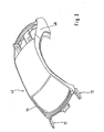
- roof module 42 On the base module 12 and the front end module 26 is one in sync with Figure 3 recognizable roof module 42 can be placed, which here lateral A-pillars 44, in the region of the roof 43rd lateral roof pillars 46, and C pillars 48 includes.
- the lower Ends of the A-pillars 44 and the C-pillars 48 are above each a cross member 50 connected together.
- the A-pillars 44 are based on composite support structure 10 in the further explained manner both on the base module 12th and on the front module 26 from.
- At the back are the lower ones Ends of the C-pillars 48 at their respective upper end the wall portions 24, wherein the modules 12,42, for example are connected together by means of an adhesive connection.
- a rear module 52 connects to the basic module 12 which together with composite support structure 10 with the rear end portion of the base module 12 to the rear Crumple of the motor vehicle belongs and a trunk after bounded at the back. To the rear, the rear module closes 52 a Heckendmodul 54 with a rear bumper, which partially visible in Fig.2.
- FIG 2 is a further perspective exploded view composed of the sub-modules 12,26,42 and 52 Support structure 10 shown which with missionbeplankungs too in the area of the front and rear fenders 56,58 and the sill 60 made of plastic, sheet metal or the like. is disguised.
- the A-pillars 44, the lateral roof pillars 46 and the C-pillars 48 are with pillar trim parts 62, 64 dressed.
- Adjacent to the roof module 42 is a lid in the form of a Bonnet 66 on, with the one inside the Vorbaumoduls 26 provided engine compartment 68 is closed at the top.
- the cover 66 is a reference to FIG Bearing assembly 69 explained in more detail with two bearings 70 held close to the roof module 42.
- the roof module 42 is visible in perspective view, their front roof pillars 44 at their lower end with bearing brackets 72 are provided, on which the bearings 70 of Support bonnet 66.
- the bearing brackets 72 may, for example be made of a box section.
- FIG 4 is an enlarged side view of a bearing 70 of Bearing assembly 69 for the hood 66 at the lower end of A-pillar 44 of the roof module 42 shown.
- From the basic module 12 is the side member 16 and the upwardly projecting column section 18 along a joining surface 74 with the side member portion 30 or with the column section 34 of the Vorbaumoduls 26 or .. connected.
- the side rail sections 16,30 and the column sections 18,34 of the basic module 12 and of Vorbaumoduls 26 each a closed in cross-section Box profile, so that after joining each other associated box profiles lateral side members 16 or door pillars 20 with approximately double in cross section, approximately 8-shaped, arise double box profile.
- the two A-pillars 44 of the roof module 42 are on the bearing brackets 72 on support surfaces 76 of Vorbaumoduls 26 and over rear lower end portions 78 of the roof pillars 44 on support surfaces 80 of the basic module 12 supported.
- the support surfaces 80 of the base module 12 are thereby through the upper ends of the Column sections 18 formed.
- the respective support surfaces 76.80 of the front end module 26 and the basic module 12 are included arranged offset in height to each other.
- the fastening of the bearing consoles 72 on the associated support surfaces 76 and the End portions 78 takes place on the associated support surfaces 80 preferably by an adhesive bond, wherein additionally Mechanical connections can be provided.
- the bearings 70 of the lid from which here essentially each include a hinge 86 with which the cover 66 to the pivot axis A pivotally mounted on the support structure 10 is.
- the hinge 86 includes a connectable to the lid 66 Hinge part 88 and one on the bearing bracket 72nd fixed hinge part 90.
- a screw for fixing the hinge part 90 on the on the storage console 72 is particularly suitable a screw, with the hinge 86 and the lid 66 is adjustable relative to the roof module 42.
- the bearing assembly in addition to the storage of the hood shown here, the bearing assembly of course also for the arrangement of other covers,
- the boot lid on the roof module 42 suitable is.
Description
Die Erfindung betrifft eine Karosserie für einen Kraftwagen der im Oberbegriff des Patentanspruchs 1 angegebenen Art.The invention relates to a body for a motor vehicle specified in the preamble of claim 1. Art.
Aus der US-A-6 334 252 ist eine Tragstruktur mit einem aufgesetzten Dachmodul als bekannt zu entnehmen, an welches eine nahe dem Dach gelagerte Motorhaube angrenzt. Die Lageranordnung der Motorhaube ist dabei direkt an dem Dachmodul angeordnet und kann somit bereits vor dem Aufsetzen des Dachmoduls auf die Tragstruktur an dem Dachmodul vormontiert werden. Oberhalb eines Strukturbauteiles - bestehend aus einem Längsträger und einem Radlaufblech - sind zwei seitliche Lagerkonsolen für die Lageranordnung angeordnet, welche oberhalb des Radlaufes verlaufen. Die Dachsäulen sind dabei auf Stützflächen der Türsäulen und die Lagerkonsolen sind an Stützflächen des Strukturbauteiles der Tragstruktur abgestützt.From US-A-6 334 252 is a support structure with an attached Roof module to be known as known, to which a adjacent hood mounted adjacent to the roof. The bearing arrangement The hood is arranged directly on the roof module and can thus already before putting the roof module on the Support structure are preassembled on the roof module. Above one Structural components - consisting of a side member and a Radlaufblech - are two lateral bearing brackets for the Bearing arrangement arranged, which extend above the wheel arch. The roof pillars are on support surfaces of the Door pillars and the bearing brackets are on support surfaces of the structural component supported the support structure.
Aus der DE 35 40 814 C2 ist bereits eine solche Karosserie als bekannt zu entnehmen, auf deren im Wesentlichen aus großformatigen Teilmodulen zusammengesetzten Tragstruktur ein Dachmodul aufgesetzt ist. In zusammengebautem Zustand der Karosserie grenzt an das vordere untere Ende des Dachmoduls eine Motorhaube zum Verschließen des Motorraums am vorderen Endbereich der Karosserie an, wobei der Deckel über eine nahe des Dachmoduls angeordnete Lageranordnung an der Karosserie gehalten ist. Aufgrund von fertigungstechnischen Toleranzen beim Zusammenfügen des Dachmoduls mit den anderen Teilmodulen ist es dabei nur mit erhöhtem technischen Aufwand möglich, die an der Tragstruktur befestigte Motorhaube oder dgl. Deckel in einer exakten Lage gegenüber dem angrenzenden Dachmodul zu positionieren. From DE 35 40 814 C2 is already such a body as to be known, on whose substantially large-format Sub-modules composite support structure a roof module is attached. In assembled condition of the body Adjacent to the front lower end of the roof module a bonnet for closing the engine compartment at the front end of the Body on, with the lid over a near the roof module arranged bearing assembly is held on the body. by virtue of of manufacturing tolerances during assembly the roof module with the other submodules it is only with increased technical effort possible, attached to the support structure fixed bonnet or the like. Lid in an exact location to position against the adjacent roof module.
Der Erfindung liegt die Aufgabe zugrunde, eine Karosserie der eingangs genannten Art zu schaffen, bei der die Lagerkonsolen sowie die Lageranordnung verbessert an der Tragstruktur abgestützt sind.The invention is based on the object, a body of to create the aforementioned type, in which the bearing brackets and the bearing assembly improves supported on the support structure are.
Bei der erfindungsgemäß vorgeschlagenen Karosserie ist die Lageranordnung des Deckels bzw. der Motorhaube direkt an dem Dachmodul angeordnet, so dass der Deckel auf relativ einfache Weise und unter Vermittlung eines hochwertigen Qualitätseindrucks in einer exakten Lage gegenüber dem angrenzenden Dachmodul positioniert werden kann. Fertigungstechnische Toleranzen, die beim Zusammenfügen des Dachmoduls mit der Tragstruktur entstehen, haben somit keine Auswirkung auf die Position des Deckels gegenüber dem angrenzenden Dachmodul.In the proposed body according to the invention is the Bearing arrangement of the lid or the hood directly on the Roof module arranged so that the lid on relatively simple Way and under the mediation of a high quality impression in an exact position opposite the adjacent roof module can be positioned. Manufacturing tolerances, when assembling the roof module with the support structure arise, thus have no effect on the position the lid opposite the adjacent roof module.
Eine technisch besonders günstige Lageranordnung umfasst jeweils ein an der zugeordneten Dachsäule des Dachmoduls befestigtes Lager, über welche eine positionsgenaue und stabile Lagerung des Deckels an dem Dachmodul gewährleistet werden kann.A technically particularly favorable bearing arrangement comprises in each case a fixed to the associated roof pillar of the roof module Bearings, over which a positionally accurate and stable Storage of the lid to the roof module are guaranteed can.
Eine besonders stabile Abstützung der Lager ist mittels von Lagerkonsolen gegeben, welche in Verlängerung der Dachsäulen an deren unteren Enden angeordnet sind. Die Lagerkonsolen ruhen dabei bevorzugt auf Stützflächen der Tragstruktur, so dass sowohl eine gute Abstützung der Lagerkonsolen mit den Lagern wie auch des gesamten Dachmoduls über die Dachsäulen erreicht wird.A particularly stable support of the bearing is by means of Bearing consoles given, which in extension of the roof pillars are arranged at the lower ends. The warehouse consoles rest preferably on support surfaces of the support structure, see above that both a good support of the bearing brackets with the Storage as well as the entire roof module on the roof pillars is reached.
Weitere Vorteile, Merkmale und Einzelheiten der Erfindung ergeben sich aus der nachfolgenden Beschreibung eines bevorzugten Ausführungsbeispieles sowie anhand der Zeichnungen; diese zeigen in
- Fig.1
- eine perspektivische Explosionsdarstellung auf die aus großformatigen Teilmodulen zusammengesetzte Tragstruktur der erfindungsgemäßen Kraftwagenkarosserie;
- Fig.2
- eine weitere perspektivische Explosionsdarstellung auf die aus Teilmodulen zusammengesetzte Tragstruktur, welche mit Außenbeplankungsteilen verkleidet ist;
- Fig.3
- eine Perspektivansicht auf ein Dachmodul, deren vordere Dachsäulen an ihrem unteren Ende Lagerkonsolen für die Lageranordnung der Motorhaube umfassen; und in
- Fig.4
- eine vergrößerte Seitenansicht auf ein Lager der Lageranordnung für die Motorhaube.
- Fig.1
- an exploded perspective view of the assembled from large-sized sub-modules support structure of the motor vehicle body according to the invention;
- Fig.2
- a further perspective exploded view of the assembled from sub-modules support structure, which is covered with Außenbeplankungsteilen;
- Figure 3
- a perspective view of a roof module, the front roof pillars comprise at its lower end bearing brackets for the bearing assembly of the hood; and in
- Figure 4
- an enlarged side view of a bearing of the bearing assembly for the hood.
In Fig.1 ist in einer perspektivischen Explosionsdarstellung
eine Tragstruktur.10 einer Kraftwagenkarosserie gezeigt, die
aus mehreren großformatigen, im weiteren noch näher beschriebenen
Teilmodulen zusammengesetzt ist. Die Teilmodule der
Tragstruktur 10 sind in dem hier gezeigten Ausführungsbeispiel
jeweils aus einer Mehrzahl von zusammengefügten Blechteilen
hergestellt; gleichfalls können die Teilmodule jedoch
auch in anderen Bauweisen, beispielsweise als sog. Spaceframe,
als Kunststoffteile, Metallgussteile, als Bauteile in
sog. Sandwich-Bauweise oder dgl. vorgefertigt sein. Insbesondere
sind dabei auch Kombinationen unterschiedlicher Bauweisen
für die zusammengefügten Teilmodule je nach Anwendung und
Belastung denkbar. Die einzelnen Module sind insbesondere über
Klebverbindungen, Schweißverbindungen oder dgl. zusammengefügt.
Gleichfalls sind andere gängig Verbindungen wie
Schraubverbindungen oder dgl. denkbar.In Fig.1 is a perspective exploded view
a Tragstruktur.10 shown a motor vehicle body, the
from several large-format, to be described in more detail below
Submodules is composed. The submodules of
Ein Grundmodul 12 der Tragstruktur 10 umfasst im wesentlichen
einen Karosserieboden 14, der seitlich von Längsträgern 16
begrenzt ist. Nach vorne reicht das Grundmodul 12 bis an Säulenabschnitte
18 von Vorderwandsäulen 20, welche von den jeweils
zugeordneten vorderen Enden der seitlichen Längsträger
16 nach oben abragen. Der Karosserieboden 14 des Grundmoduls
12 endet in einem erheblichen Abstand hinter dem vorderen Ende
des Grundmoduls 12 bzw. hinter den Säulenabschnitten 18
der Vorderwandsäulen 20. Hinten endet das Grundmodul 12 hinter
hinteren Radhäusern 22, oberhalb denen Wandbereiche 24
der jeweiligen hinteren Seitenwand angeordnet sind. Das
Grundmodul 12 wird bereits vor dem Zusammenfügen mit den anderen
Teilmodulen so weit als möglich ausgestattet.A
Mit dem Grundmodul 12 ist ein Vorbaumodul 26 verbunden, welches
zur vorderen Knautschzone des Kraftwagens gehört und
crashstabil am Grundmodul 12 abgestützt ist. Hierzu umfasst
das Vorbaumodul 26 einen vorderen Endbereich 28 des Karosseriebodens
14, welcher sich zwischen seitlichen Längsträgerabschnitten
30 des Vorbaumoduls 26 erstreckt. Nach vorne endet
der vordere Endbereich 28 des Karosseriebodens 14 an einer
vorderen Stirnwand 32 der Fahrgastzelle, welche sich vom vorderen
Endbereich 28 des Karosseriebodens 14 bis etwa auf Höhe
der Bordwandkante der Tragstruktur 10 erstreckt. Seitlich
wird die Stirnwand 32 von Säulenabschnitten 34 der Vorderwandsäulen
20 begrenzt, welche von den seitlichen Längsträgerabschnitten
30 des Vorbaumoduls 34 nach oben abragen. Am
vorderen Ende des Vorbaumoduls 34 sind vordere Längsträger 36
sowie vordere Seitenwandbereiche 38 erkennbar. Nach vorne
schließt sich an das Vorbaumodul 26 ein Frontmodul 40 an,
welches in Fig.2 teilweise dargestellt ist und beispielsweise
den vorderen Stoßfänger umfasst.To the
Auf das Grundmodul 12 und das Vorbaumodul 26 ist ein in Zusammenschau
mit Fig.3 erkennbares Dachmodul 42 aufsetzbar,
welches hier seitliche A-Säulen 44, im Bereich des Dachs 43
seitliche Dachsäulen 46, und C-Säulen 48 umfasst. Die unteren
Enden der A-Säulen 44 bzw. der C-Säulen 48 sind über jeweils
ein Querträgerelement 50 miteinander verbunden. Die A-Säulen
44 stützen sich bei zusammengesetzter Tragstruktur 10 auf im
weiteren noch erläuterte Weise sowohl an dem Grundmodul 12
als auch am Vorbaumodul 26 ab. Hinten stützen sich die unteren
Enden der C-Säulen 48 am jeweils zugeordneten oberen Ende
der Wandbereiche 24 ab, wobei die Module 12,42 beispielsweise
mittels einer Klebeverbindung miteinander verbunden sind.On the
Hinten schließt sich an das Grundmodul 12 ein Heckmodul 52
an, welches bei zusammengesetzter Tragstruktur 10 zusammen
mit dem hinteren Endbereich des Grundmoduls 12 zur hinteren
Knautschzone des Kraftwagens gehört und einen Kofferraum nach
hinten begrenzt. Nach hinten schließt sich an das Heckmodul
52 ein Heckendmodul 54 mit einem hinteren Stoßfänger an, welches
in Fig.2 teilweise erkennbar ist.At the rear, a
In Fig.2 ist in einer weiteren perspektivischen Explosionsdarstellung
die aus den Teilmodulen 12,26,42 und 52 zusammengesetzte
Tragstruktur 10 dargestellt, welche mit Außenbeplankungsteilen
im Bereich der vorderen und hinteren Kotflügel
56,58 sowie des Schwellers 60 aus Kunststoff, Blech oder dgl.
verkleidet ist. Die A-Säulen 44, die seitlichen Dachsäulen 46
und die C-Säulen 48 sind mit Säulenverkleidungsteilen 62,64
verkleidet. An das Dachmodul 42 grenzt ein Deckel in Form einer
Motorhaube 66 an, mit der ein innerhalb des Vorbaumoduls
26 vorgesehener Motorraum 68 nach oben hin verschlossen ist.
Der Deckel 66 ist dabei über eine unter Bezugnahme auf Fig.4
noch näher erläuterte Lageranordnung 69 mit zwei Lagern 70
nahe an dem Dachmodul 42 gehalten.In Figure 2 is a further perspective exploded view
composed of the
In Fig.3 ist in Perspektivansicht das Dachmodul 42 erkennbar,
deren vordere Dachsäulen 44 an ihrem unteren Ende mit Lagerkonsolen
72 versehen sind, auf welchen sich die Lager 70 der
Motorhaube 66 abstützen. Die Lagerkonsolen 72 können zum Beispiel
aus einem Kastenprofil hergestellt sein.3, the
In Fig.4 ist eine vergrößerte Seitenansicht ein Lager 70 der
Lageranordnung 69 für die Motorhaube 66 am unteren Ende der
A-Säule 44 des Dachmoduls 42 gezeigt. Von dem Grundmodul 12
ist der Längsträger 16 und der nach oben abragenden Säulenabschnitt
18 entlang einer Fügefläche 74 mit dem Längsträgerabschnitt
30 bzw. mit dem Säulenabschnitt 34 des Vorbaumoduls
26 bzw.. verbunden. Dabei haben die Längsträgerabschnitte
16,30 und die Säulenabschnitte 18,34 des Grundmoduls 12 und
des Vorbaumoduls 26 jeweils ein im Querschnitt geschlossenes
Kastenprofil, so dass nach dem Zusammenfügen der einander jeweils
zugeordneten Kastenprofile seitliche Längsträger 16
bzw. Türsäulen 20 mit im Querschnitt doppeltem, etwa 8-förmigen,
doppeltem Kastenprofil entstehen.In Figure 4 is an enlarged side view of a
Die beiden A-Säulen 44 des Dachmoduls 42 sind über die Lagerkonsolen
72 auf Stützflächen 76 des Vorbaumoduls 26 und über
hintere untere Endabschnitte 78 der Dachsäulen 44 auf Stützflächen
80 des Grundmoduls 12 abgestützt. Die Stützflächen 80
des Grundmoduls 12 werden dabei durch die oberen Enden der
Säulenabschnitte 18 gebildet. Die jeweiligen Stützflächen
76,80 des Vorbaumoduls 26 und des Grundmoduls 12 sind dabei
höhenversetzt zueinander angeordnet. Die Befestigung der Lagerkonsolen
72 auf den zugeordneten Stützflächen 76 bzw. der
Endabschnitte 78 auf den zugeordneten Stützflächen 80 erfolgt
dabei bevorzugt durch eine Klebeverbindung, wobei zusätzlich
mechanische Verbindungen vorgesehen sein können.The two A-pillars 44 of the
Auf der hier ebenen Oberseite 84 der Lagerkonsolen 72 stützen
sich die Lager 70 des Deckels ab, welche hier im wesentlichen
jeweils ein Scharnier 86 umfassen, mit denen der Deckel 66 um
die Schwenkachse A an der Tragstruktur 10 schwenkgelagert
ist. Das Scharnier 86 umfasst einen mit dem Deckel 66 verbindbaren
Scharnierteil 88 und einen auf der Lagerkonsole 72
befestigten Scharnierteil 90. Zur Befestigung des Scharnierteils
90 auf der auf der Lagerkonsole 72 eignet sich besonders
eine Schraubverbindung, mit der das Scharnier 86 bzw.
der Deckel 66 gegenüber dem Dachmodul 42 einstellbar ist.Support on the here
Als im Rahmen der Erfindung mitumfasst ist es zu betrachten,
dass neben der hier gezeigten Lagerung der Motorhaube die Lageranordnung
natürlich auch zur Anordnung anderer Deckel,
beispielsweise des Kofferraumdeckels an dem Dachmodul 42 geeignet
ist.As encompassed within the scope of the invention, it is to be considered
that in addition to the storage of the hood shown here, the bearing assembly
of course also for the arrangement of other covers,
For example, the boot lid on the
Claims (6)
- Motor vehicle body, having a roof module (42) which is placed onto a supporting structure (10), with the following features:characterized by the following features,a lid (bonnet 66) for closing a compartment (engine compartment 68) at one end region of the body adjoins the roof module (42),the lid (66) is arranged directly on the roof module (42) via a bearing arrangement (69) and can already be preassembled on the roof module (42) before the roof module (42) is placed onto the supporting structure (10),the roof module (42) is provided at the lower ends of the roof pillars (44) with a respective bearing console (72) for the bearing arrangement (69),the roof pillars (44) are supported on supporting surfaces (80) of the door pillars (20) and the bearing consoles (72) are supported on supporting surfaces (76) of the supporting structure (10),that the door pillars (20) are joined together from two pillar sections (18, 34), andthat the roof pillars (44) are supported on the respectively assigned supporting surfaces (80) of the one pillar section (18) and the bearing consoles (72) are supported on the respectively assigned supporting surfaces (76) of the further pillar section (34).
- Body according to Claim 1, characterized in that the further pillar sections (34) are assigned to a front-end module (26) of the supporting structure (10).
- Body according to Claim 2, characterized in that the further pillar sections (34) protrude upwards from the lateral longitudinal member sections (30) of the front-end module (26).
- Body according to Claim 1, characterized in that the supporting surfaces (76, 80) of the pillar sections (18, 34) are arranged offset in height with respect to each other.
- Body according to Claim 1, characterized in that an associated bearing (70) of the lid (66) is supported in each case on the bearing consoles (72).
- Body according to Claim 5, characterized in that the bearings (70) in each case comprise a hinge (86) with which the lid (66) is mounted pivotally on the supporting structure (10).
Applications Claiming Priority (3)
| Application Number | Priority Date | Filing Date | Title |
|---|---|---|---|
| DE10239988A DE10239988A1 (en) | 2002-08-27 | 2002-08-27 | Body for a motor vehicle |
| DE10239988 | 2002-08-27 | ||
| PCT/EP2003/008817 WO2004024542A1 (en) | 2002-08-27 | 2003-08-08 | Motor vehicle body |
Publications (2)
| Publication Number | Publication Date |
|---|---|
| EP1532039A1 EP1532039A1 (en) | 2005-05-25 |
| EP1532039B1 true EP1532039B1 (en) | 2005-11-30 |
Family
ID=31983888
Family Applications (1)
| Application Number | Title | Priority Date | Filing Date |
|---|---|---|---|
| EP03794854A Expired - Lifetime EP1532039B1 (en) | 2002-08-27 | 2003-08-08 | Motor vehicle body |
Country Status (7)
| Country | Link |
|---|---|
| US (1) | US20060175871A1 (en) |
| EP (1) | EP1532039B1 (en) |
| JP (1) | JP2005537181A (en) |
| KR (1) | KR20050038036A (en) |
| CN (1) | CN1684865A (en) |
| DE (2) | DE10239988A1 (en) |
| WO (1) | WO2004024542A1 (en) |
Families Citing this family (29)
| Publication number | Priority date | Publication date | Assignee | Title |
|---|---|---|---|---|
| US8505258B2 (en) | 2000-08-17 | 2013-08-13 | Industrial Origami, Inc. | Load-bearing three-dimensional structure |
| US7534501B2 (en) | 2000-08-17 | 2009-05-19 | Industrial Origami, Inc. | Precision-folded, high strength, fatigue-resistant structures and sheet therefor |
| DE10239990B4 (en) * | 2002-08-27 | 2007-10-25 | Daimlerchrysler Ag | Car body with a support structure of large-sized sub-modules |
| JP4590853B2 (en) | 2003-10-17 | 2010-12-01 | パナソニック株式会社 | Rotation rate sensor and multi-axis detection type rotation rate sensor |
| DE102005055812B4 (en) * | 2005-11-21 | 2007-12-13 | Edscha Cabrio-Dachsysteme Gmbh | support device |
| WO2008052174A2 (en) | 2006-10-26 | 2008-05-02 | Industrial Origami, Inc. | Forming three dimensional object |
| DE102006051594B4 (en) * | 2006-11-02 | 2012-03-29 | Wilhelm Karmann Gmbh | Method for assembling a hardtop convertible top |
| US7591502B2 (en) * | 2007-01-11 | 2009-09-22 | Ford Motor Company | Tunable inner fender structure |
| US7798560B2 (en) * | 2007-01-11 | 2010-09-21 | Ford Motor Company | Vehicle body structure |
| US8177277B2 (en) * | 2007-01-11 | 2012-05-15 | Ford Motor Company | Vehicle having a body panel |
| US7850226B2 (en) | 2007-01-11 | 2010-12-14 | Ford Motor Company | Vehicle having a passenger compartment body structure |
| US7810876B2 (en) * | 2007-01-11 | 2010-10-12 | Ford Motor Company | Vehicle having a rear end body structure |
| US7677649B2 (en) * | 2007-01-11 | 2010-03-16 | Ford Motor Company | Vehicle having an interlocking floor assembly |
| US8123284B2 (en) * | 2007-01-11 | 2012-02-28 | Ford Motor Company | Vehicle body component and mating feature |
| US8317964B2 (en) * | 2007-01-11 | 2012-11-27 | Ford Motor Company | Method of manufacturing a vehicle |
| US7849601B2 (en) * | 2007-01-11 | 2010-12-14 | Ford Motor Company | Method of manufacturing a vehicle |
| US8038205B2 (en) * | 2007-01-11 | 2011-10-18 | Ford Motor Company | Vehicle having a passenger compartment body structure |
| US7703841B2 (en) * | 2007-01-11 | 2010-04-27 | Ford Motor Company | Vehicle body assembly |
| US7717465B2 (en) * | 2007-01-11 | 2010-05-18 | Ford Motor Company | Vehicle having an engine support structure |
| US7618087B2 (en) * | 2007-01-11 | 2009-11-17 | Ford Motor Company | Vehicle having a front end body structure |
| CN102198843B (en) * | 2010-03-23 | 2013-02-20 | 本田技研工业株式会社 | Vehicle side body structure |
| JP5422734B2 (en) * | 2010-03-23 | 2014-02-19 | 本田技研工業株式会社 | Body side structure |
| CN102774426A (en) * | 2011-05-11 | 2012-11-14 | 牛基旭 | Machine cover and vehicle roof integrated structure |
| JP5331849B2 (en) * | 2011-07-06 | 2013-10-30 | 本田技研工業株式会社 | Body front structure |
| US8936164B2 (en) | 2012-07-06 | 2015-01-20 | Industrial Origami, Inc. | Solar panel rack |
| CN104670363B (en) * | 2014-12-20 | 2017-01-18 | 北汽银翔汽车有限公司 | Engine hood aligning mechanism |
| KR101738039B1 (en) * | 2015-10-23 | 2017-05-19 | 현대자동차주식회사 | Structure of hybrid-front pillar |
| KR20210061529A (en) * | 2019-11-20 | 2021-05-28 | 현대자동차주식회사 | Roof carrier for vehicle |
| DE102020117209A1 (en) * | 2020-06-30 | 2021-12-30 | Bayerische Motoren Werke Aktiengesellschaft | Method for manufacturing a body for a motor vehicle and a body for a motor vehicle |
Family Cites Families (4)
| Publication number | Priority date | Publication date | Assignee | Title |
|---|---|---|---|---|
| DE3540814A1 (en) * | 1985-11-16 | 1987-05-21 | Opel Adam Ag | Vehicle body for passenger cars and method for producing such a body |
| EP1008510B1 (en) * | 1998-12-11 | 2013-03-06 | Nissan Motor Company Limited | Production of vehicles |
| US6493920B1 (en) * | 2000-09-07 | 2002-12-17 | Ford Global Technologies, Inc. | Method of assembling a vehicle from preassembled modular components |
| DE10049894A1 (en) * | 2000-10-10 | 2002-04-11 | Bayerische Motoren Werke Ag | Hatchback has opening roof section and rear vent which can be raised above normal roof level, side sections of flexible material being attached to these and forming watertight seal with them |
-
2002
- 2002-08-27 DE DE10239988A patent/DE10239988A1/en not_active Withdrawn
-
2003
- 2003-08-08 WO PCT/EP2003/008817 patent/WO2004024542A1/en not_active Application Discontinuation
- 2003-08-08 KR KR1020057003413A patent/KR20050038036A/en not_active Application Discontinuation
- 2003-08-08 US US10/526,122 patent/US20060175871A1/en not_active Abandoned
- 2003-08-08 DE DE50301824T patent/DE50301824D1/en not_active Expired - Lifetime
- 2003-08-08 CN CNA038230593A patent/CN1684865A/en active Pending
- 2003-08-08 EP EP03794854A patent/EP1532039B1/en not_active Expired - Lifetime
- 2003-08-08 JP JP2004535067A patent/JP2005537181A/en active Pending
Also Published As
| Publication number | Publication date |
|---|---|
| EP1532039A1 (en) | 2005-05-25 |
| DE50301824D1 (en) | 2006-01-05 |
| KR20050038036A (en) | 2005-04-25 |
| WO2004024542A1 (en) | 2004-03-25 |
| DE10239988A1 (en) | 2004-04-15 |
| CN1684865A (en) | 2005-10-19 |
| US20060175871A1 (en) | 2006-08-10 |
| JP2005537181A (en) | 2005-12-08 |
Similar Documents
| Publication | Publication Date | Title |
|---|---|---|
| EP1532039B1 (en) | Motor vehicle body | |
| DE10239990B4 (en) | Car body with a support structure of large-sized sub-modules | |
| EP1532040B1 (en) | Motor vehicle body comprising a support structure composed of large-size partial modules | |
| DE4013784C2 (en) | Car body, in particular for passenger cars | |
| EP1525132B1 (en) | Floor-supporting arrangement in motor vehicles | |
| DE102007006722C5 (en) | Carrier for a body of a motor vehicle | |
| DE19730404B4 (en) | Subframe for motor vehicles | |
| DE19917177B4 (en) | Support structure for motor vehicles | |
| EP1534578B1 (en) | Body comprising a support structure made of assembled partial modules | |
| DE10063417A1 (en) | Lightweight door for motor vehicles | |
| DE19819446A1 (en) | Body structure of a motor vehicle | |
| DE102010051271A1 (en) | Motor vehicle body with reinforcing structure | |
| DE102006052992A1 (en) | Frame structure for motor vehicle i.e. passenger car, has two parallel sillboards provided on sides of tunnel, and dashboard cowl provided with closing plate, which is directly connected with sillboards and tunnel | |
| DE102016123879A1 (en) | VEHICLE WITH SLIDING ROOF AND PANORAMA LASH | |
| EP2399806A2 (en) | Rear end car bodywork | |
| DE19912106A1 (en) | Motor vehicle, in particular passenger cars | |
| DE19956567B4 (en) | Vehicle roof and roof spar of a vehicle roof | |
| DE102005033030A1 (en) | Frontal bodywork for motor vehicle has accessory space defined at front of engine bay with accessory panel having stiffening strip | |
| EP1712452A2 (en) | Passenger compartment for a motor car | |
| DE10239991A1 (en) | Body for a motor vehicle with a roof pillar | |
| DE3702619A1 (en) | Passenger car and method for the production of a car of this type | |
| DE60123731T2 (en) | Body side part for a motor vehicle | |
| EP1083071B1 (en) | Convertible vehicle soft top element and convertible vehicle soft top | |
| EP2615014A2 (en) | Driver's cab for a vehicle | |
| DE202006010160U1 (en) | Hardtop structure for vehicle bodywork has hard roof able to be mounted over open passenger compartment towards rear end of bodywork as for estate car |
Legal Events
| Date | Code | Title | Description |
|---|---|---|---|
| PUAI | Public reference made under article 153(3) epc to a published international application that has entered the european phase |
Free format text: ORIGINAL CODE: 0009012 |
|
| 17P | Request for examination filed |
Effective date: 20050223 |
|
| AK | Designated contracting states |
Kind code of ref document: A1 Designated state(s): AT BE BG CH CY CZ DE DK EE ES FI FR GB GR HU IE IT LI LU MC NL PT RO SE SI SK TR |
|
| GRAP | Despatch of communication of intention to grant a patent |
Free format text: ORIGINAL CODE: EPIDOSNIGR1 |
|
| RBV | Designated contracting states (corrected) |
Designated state(s): DE ES FR GB IT SE |
|
| GRAS | Grant fee paid |
Free format text: ORIGINAL CODE: EPIDOSNIGR3 |
|
| GRAA | (expected) grant |
Free format text: ORIGINAL CODE: 0009210 |
|
| AK | Designated contracting states |
Kind code of ref document: B1 Designated state(s): DE ES FR GB IT SE |
|
| PG25 | Lapsed in a contracting state [announced via postgrant information from national office to epo] |
Ref country code: IT Free format text: LAPSE BECAUSE OF FAILURE TO SUBMIT A TRANSLATION OF THE DESCRIPTION OR TO PAY THE FEE WITHIN THE PRESCRIBED TIME-LIMIT;WARNING: LAPSES OF ITALIAN PATENTS WITH EFFECTIVE DATE BEFORE 2007 MAY HAVE OCCURRED AT ANY TIME BEFORE 2007. THE CORRECT EFFECTIVE DATE MAY BE DIFFERENT FROM THE ONE RECORDED. Effective date: 20051130 Ref country code: GB Free format text: LAPSE BECAUSE OF FAILURE TO SUBMIT A TRANSLATION OF THE DESCRIPTION OR TO PAY THE FEE WITHIN THE PRESCRIBED TIME-LIMIT Effective date: 20051130 |
|
| REG | Reference to a national code |
Ref country code: GB Ref legal event code: FG4D Free format text: NOT ENGLISH |
|
| RIN1 | Information on inventor provided before grant (corrected) |
Inventor name: VALDIVIESO, CARLOS Inventor name: MAYER, CHRISTIAN Inventor name: EIPPER, KONRAD Inventor name: FUSSNEGGER, WOLFGANG Inventor name: SPIES, BERNHARD |
|
| REF | Corresponds to: |
Ref document number: 50301824 Country of ref document: DE Date of ref document: 20060105 Kind code of ref document: P |
|
| PG25 | Lapsed in a contracting state [announced via postgrant information from national office to epo] |
Ref country code: SE Free format text: LAPSE BECAUSE OF FAILURE TO SUBMIT A TRANSLATION OF THE DESCRIPTION OR TO PAY THE FEE WITHIN THE PRESCRIBED TIME-LIMIT Effective date: 20060228 |
|
| PG25 | Lapsed in a contracting state [announced via postgrant information from national office to epo] |
Ref country code: ES Free format text: LAPSE BECAUSE OF FAILURE TO SUBMIT A TRANSLATION OF THE DESCRIPTION OR TO PAY THE FEE WITHIN THE PRESCRIBED TIME-LIMIT Effective date: 20060313 |
|
| GBV | Gb: ep patent (uk) treated as always having been void in accordance with gb section 77(7)/1977 [no translation filed] |
Effective date: 20051130 |
|
| PLBE | No opposition filed within time limit |
Free format text: ORIGINAL CODE: 0009261 |
|
| STAA | Information on the status of an ep patent application or granted ep patent |
Free format text: STATUS: NO OPPOSITION FILED WITHIN TIME LIMIT |
|
| 26N | No opposition filed |
Effective date: 20060831 |
|
| EN | Fr: translation not filed | ||
| PG25 | Lapsed in a contracting state [announced via postgrant information from national office to epo] |
Ref country code: FR Free format text: LAPSE BECAUSE OF FAILURE TO SUBMIT A TRANSLATION OF THE DESCRIPTION OR TO PAY THE FEE WITHIN THE PRESCRIBED TIME-LIMIT Effective date: 20070119 |
|
| PG25 | Lapsed in a contracting state [announced via postgrant information from national office to epo] |
Ref country code: FR Free format text: LAPSE BECAUSE OF FAILURE TO SUBMIT A TRANSLATION OF THE DESCRIPTION OR TO PAY THE FEE WITHIN THE PRESCRIBED TIME-LIMIT Effective date: 20051130 |
|
| PGFP | Annual fee paid to national office [announced via postgrant information from national office to epo] |
Ref country code: DE Payment date: 20161031 Year of fee payment: 14 |
|
| REG | Reference to a national code |
Ref country code: DE Ref legal event code: R119 Ref document number: 50301824 Country of ref document: DE |
|
| PG25 | Lapsed in a contracting state [announced via postgrant information from national office to epo] |
Ref country code: DE Free format text: LAPSE BECAUSE OF NON-PAYMENT OF DUE FEES Effective date: 20180301 |