EP1530960A1 - Dispositif de massage - Google Patents
Dispositif de massage Download PDFInfo
- Publication number
- EP1530960A1 EP1530960A1 EP04025194A EP04025194A EP1530960A1 EP 1530960 A1 EP1530960 A1 EP 1530960A1 EP 04025194 A EP04025194 A EP 04025194A EP 04025194 A EP04025194 A EP 04025194A EP 1530960 A1 EP1530960 A1 EP 1530960A1
- Authority
- EP
- European Patent Office
- Prior art keywords
- massage
- rotation shaft
- pressing
- parts
- massage apparatus
- Prior art date
- Legal status (The legal status is an assumption and is not a legal conclusion. Google has not performed a legal analysis and makes no representation as to the accuracy of the status listed.)
- Withdrawn
Links
- 230000002093 peripheral effect Effects 0.000 claims abstract description 17
- NJPPVKZQTLUDBO-UHFFFAOYSA-N novaluron Chemical compound C1=C(Cl)C(OC(F)(F)C(OC(F)(F)F)F)=CC=C1NC(=O)NC(=O)C1=C(F)C=CC=C1F NJPPVKZQTLUDBO-UHFFFAOYSA-N 0.000 claims description 6
- 230000000694 effects Effects 0.000 abstract description 15
- 239000000758 substrate Substances 0.000 description 22
- 210000002414 leg Anatomy 0.000 description 12
- 230000000638 stimulation Effects 0.000 description 9
- PPBRXRYQALVLMV-UHFFFAOYSA-N Styrene Chemical compound C=CC1=CC=CC=C1 PPBRXRYQALVLMV-UHFFFAOYSA-N 0.000 description 6
- 230000003247 decreasing effect Effects 0.000 description 5
- JOYRKODLDBILNP-UHFFFAOYSA-N Ethyl urethane Chemical compound CCOC(N)=O JOYRKODLDBILNP-UHFFFAOYSA-N 0.000 description 3
- 229910000831 Steel Inorganic materials 0.000 description 3
- 150000001336 alkenes Chemical class 0.000 description 3
- 238000007373 indentation Methods 0.000 description 3
- JRZJOMJEPLMPRA-UHFFFAOYSA-N olefin Natural products CCCCCCCC=C JRZJOMJEPLMPRA-UHFFFAOYSA-N 0.000 description 3
- 229920001084 poly(chloroprene) Polymers 0.000 description 3
- -1 polyethylene form Polymers 0.000 description 3
- 239000011347 resin Substances 0.000 description 3
- 229920005989 resin Polymers 0.000 description 3
- 230000000630 rising effect Effects 0.000 description 3
- 239000010959 steel Substances 0.000 description 3
- 229920003048 styrene butadiene rubber Polymers 0.000 description 3
- 229920003051 synthetic elastomer Polymers 0.000 description 3
- 239000005061 synthetic rubber Substances 0.000 description 3
- 229920002725 thermoplastic elastomer Polymers 0.000 description 3
- 210000000689 upper leg Anatomy 0.000 description 3
- 239000013013 elastic material Substances 0.000 description 2
- 239000010985 leather Substances 0.000 description 2
- 239000000463 material Substances 0.000 description 2
- 239000004698 Polyethylene Substances 0.000 description 1
- 244000309466 calf Species 0.000 description 1
- 235000012489 doughnuts Nutrition 0.000 description 1
- 239000004744 fabric Substances 0.000 description 1
- 239000004033 plastic Substances 0.000 description 1
- 229920003023 plastic Polymers 0.000 description 1
- 229920000573 polyethylene Polymers 0.000 description 1
- 229920001155 polypropylene Polymers 0.000 description 1
- 230000000717 retained effect Effects 0.000 description 1
Images


Classifications
-
- A—HUMAN NECESSITIES
- A61—MEDICAL OR VETERINARY SCIENCE; HYGIENE
- A61H—PHYSICAL THERAPY APPARATUS, e.g. DEVICES FOR LOCATING OR STIMULATING REFLEX POINTS IN THE BODY; ARTIFICIAL RESPIRATION; MASSAGE; BATHING DEVICES FOR SPECIAL THERAPEUTIC OR HYGIENIC PURPOSES OR SPECIFIC PARTS OF THE BODY
- A61H15/00—Massage by means of rollers, balls, e.g. inflatable, chains, or roller chains
-
- A—HUMAN NECESSITIES
- A61—MEDICAL OR VETERINARY SCIENCE; HYGIENE
- A61H—PHYSICAL THERAPY APPARATUS, e.g. DEVICES FOR LOCATING OR STIMULATING REFLEX POINTS IN THE BODY; ARTIFICIAL RESPIRATION; MASSAGE; BATHING DEVICES FOR SPECIAL THERAPEUTIC OR HYGIENIC PURPOSES OR SPECIFIC PARTS OF THE BODY
- A61H23/00—Percussion or vibration massage, e.g. using supersonic vibration; Suction-vibration massage; Massage with moving diaphragms
- A61H23/02—Percussion or vibration massage, e.g. using supersonic vibration; Suction-vibration massage; Massage with moving diaphragms with electric or magnetic drive
- A61H23/0254—Percussion or vibration massage, e.g. using supersonic vibration; Suction-vibration massage; Massage with moving diaphragms with electric or magnetic drive with rotary motor
-
- A—HUMAN NECESSITIES
- A61—MEDICAL OR VETERINARY SCIENCE; HYGIENE
- A61H—PHYSICAL THERAPY APPARATUS, e.g. DEVICES FOR LOCATING OR STIMULATING REFLEX POINTS IN THE BODY; ARTIFICIAL RESPIRATION; MASSAGE; BATHING DEVICES FOR SPECIAL THERAPEUTIC OR HYGIENIC PURPOSES OR SPECIFIC PARTS OF THE BODY
- A61H1/00—Apparatus for passive exercising; Vibrating apparatus; Chiropractic devices, e.g. body impacting devices, external devices for briefly extending or aligning unbroken bones
- A61H1/008—Apparatus for applying pressure or blows almost perpendicular to the body or limb axis, e.g. chiropractic devices for repositioning vertebrae, correcting deformation
-
- A—HUMAN NECESSITIES
- A61—MEDICAL OR VETERINARY SCIENCE; HYGIENE
- A61H—PHYSICAL THERAPY APPARATUS, e.g. DEVICES FOR LOCATING OR STIMULATING REFLEX POINTS IN THE BODY; ARTIFICIAL RESPIRATION; MASSAGE; BATHING DEVICES FOR SPECIAL THERAPEUTIC OR HYGIENIC PURPOSES OR SPECIFIC PARTS OF THE BODY
- A61H15/00—Massage by means of rollers, balls, e.g. inflatable, chains, or roller chains
- A61H2015/0007—Massage by means of rollers, balls, e.g. inflatable, chains, or roller chains with balls or rollers rotating about their own axis
- A61H2015/0014—Massage by means of rollers, balls, e.g. inflatable, chains, or roller chains with balls or rollers rotating about their own axis cylinder-like, i.e. rollers
-
- A—HUMAN NECESSITIES
- A61—MEDICAL OR VETERINARY SCIENCE; HYGIENE
- A61H—PHYSICAL THERAPY APPARATUS, e.g. DEVICES FOR LOCATING OR STIMULATING REFLEX POINTS IN THE BODY; ARTIFICIAL RESPIRATION; MASSAGE; BATHING DEVICES FOR SPECIAL THERAPEUTIC OR HYGIENIC PURPOSES OR SPECIFIC PARTS OF THE BODY
- A61H15/00—Massage by means of rollers, balls, e.g. inflatable, chains, or roller chains
- A61H2015/0007—Massage by means of rollers, balls, e.g. inflatable, chains, or roller chains with balls or rollers rotating about their own axis
- A61H2015/0028—Massage by means of rollers, balls, e.g. inflatable, chains, or roller chains with balls or rollers rotating about their own axis disc-like, i.e. diameter substantially greater than width
-
- A—HUMAN NECESSITIES
- A61—MEDICAL OR VETERINARY SCIENCE; HYGIENE
- A61H—PHYSICAL THERAPY APPARATUS, e.g. DEVICES FOR LOCATING OR STIMULATING REFLEX POINTS IN THE BODY; ARTIFICIAL RESPIRATION; MASSAGE; BATHING DEVICES FOR SPECIAL THERAPEUTIC OR HYGIENIC PURPOSES OR SPECIFIC PARTS OF THE BODY
- A61H2201/00—Characteristics of apparatus not provided for in the preceding codes
- A61H2201/01—Constructive details
- A61H2201/0157—Constructive details portable
-
- A—HUMAN NECESSITIES
- A61—MEDICAL OR VETERINARY SCIENCE; HYGIENE
- A61H—PHYSICAL THERAPY APPARATUS, e.g. DEVICES FOR LOCATING OR STIMULATING REFLEX POINTS IN THE BODY; ARTIFICIAL RESPIRATION; MASSAGE; BATHING DEVICES FOR SPECIAL THERAPEUTIC OR HYGIENIC PURPOSES OR SPECIFIC PARTS OF THE BODY
- A61H2201/00—Characteristics of apparatus not provided for in the preceding codes
- A61H2201/01—Constructive details
- A61H2201/0165—Damping, vibration related features
- A61H2201/0169—Noise reduction
-
- A—HUMAN NECESSITIES
- A61—MEDICAL OR VETERINARY SCIENCE; HYGIENE
- A61H—PHYSICAL THERAPY APPARATUS, e.g. DEVICES FOR LOCATING OR STIMULATING REFLEX POINTS IN THE BODY; ARTIFICIAL RESPIRATION; MASSAGE; BATHING DEVICES FOR SPECIAL THERAPEUTIC OR HYGIENIC PURPOSES OR SPECIFIC PARTS OF THE BODY
- A61H2201/00—Characteristics of apparatus not provided for in the preceding codes
- A61H2201/12—Driving means
- A61H2201/1207—Driving means with electric or magnetic drive
- A61H2201/1215—Rotary drive
-
- A—HUMAN NECESSITIES
- A61—MEDICAL OR VETERINARY SCIENCE; HYGIENE
- A61H—PHYSICAL THERAPY APPARATUS, e.g. DEVICES FOR LOCATING OR STIMULATING REFLEX POINTS IN THE BODY; ARTIFICIAL RESPIRATION; MASSAGE; BATHING DEVICES FOR SPECIAL THERAPEUTIC OR HYGIENIC PURPOSES OR SPECIFIC PARTS OF THE BODY
- A61H2201/00—Characteristics of apparatus not provided for in the preceding codes
- A61H2201/14—Special force transmission means, i.e. between the driving means and the interface with the user
- A61H2201/1418—Cam
-
- A—HUMAN NECESSITIES
- A61—MEDICAL OR VETERINARY SCIENCE; HYGIENE
- A61H—PHYSICAL THERAPY APPARATUS, e.g. DEVICES FOR LOCATING OR STIMULATING REFLEX POINTS IN THE BODY; ARTIFICIAL RESPIRATION; MASSAGE; BATHING DEVICES FOR SPECIAL THERAPEUTIC OR HYGIENIC PURPOSES OR SPECIFIC PARTS OF THE BODY
- A61H2201/00—Characteristics of apparatus not provided for in the preceding codes
- A61H2201/14—Special force transmission means, i.e. between the driving means and the interface with the user
- A61H2201/1436—Special crank assembly
-
- A—HUMAN NECESSITIES
- A61—MEDICAL OR VETERINARY SCIENCE; HYGIENE
- A61H—PHYSICAL THERAPY APPARATUS, e.g. DEVICES FOR LOCATING OR STIMULATING REFLEX POINTS IN THE BODY; ARTIFICIAL RESPIRATION; MASSAGE; BATHING DEVICES FOR SPECIAL THERAPEUTIC OR HYGIENIC PURPOSES OR SPECIFIC PARTS OF THE BODY
- A61H2201/00—Characteristics of apparatus not provided for in the preceding codes
- A61H2201/16—Physical interface with patient
- A61H2201/1602—Physical interface with patient kind of interface, e.g. head rest, knee support or lumbar support
- A61H2201/164—Feet or leg, e.g. pedal
-
- A—HUMAN NECESSITIES
- A61—MEDICAL OR VETERINARY SCIENCE; HYGIENE
- A61H—PHYSICAL THERAPY APPARATUS, e.g. DEVICES FOR LOCATING OR STIMULATING REFLEX POINTS IN THE BODY; ARTIFICIAL RESPIRATION; MASSAGE; BATHING DEVICES FOR SPECIAL THERAPEUTIC OR HYGIENIC PURPOSES OR SPECIFIC PARTS OF THE BODY
- A61H2201/00—Characteristics of apparatus not provided for in the preceding codes
- A61H2201/16—Physical interface with patient
- A61H2201/1657—Movement of interface, i.e. force application means
- A61H2201/1664—Movement of interface, i.e. force application means linear
- A61H2201/1669—Movement of interface, i.e. force application means linear moving along the body in a reciprocating manner
-
- A—HUMAN NECESSITIES
- A61—MEDICAL OR VETERINARY SCIENCE; HYGIENE
- A61H—PHYSICAL THERAPY APPARATUS, e.g. DEVICES FOR LOCATING OR STIMULATING REFLEX POINTS IN THE BODY; ARTIFICIAL RESPIRATION; MASSAGE; BATHING DEVICES FOR SPECIAL THERAPEUTIC OR HYGIENIC PURPOSES OR SPECIFIC PARTS OF THE BODY
- A61H2205/00—Devices for specific parts of the body
- A61H2205/10—Leg
- A61H2205/106—Leg for the lower legs
-
- A—HUMAN NECESSITIES
- A61—MEDICAL OR VETERINARY SCIENCE; HYGIENE
- A61H—PHYSICAL THERAPY APPARATUS, e.g. DEVICES FOR LOCATING OR STIMULATING REFLEX POINTS IN THE BODY; ARTIFICIAL RESPIRATION; MASSAGE; BATHING DEVICES FOR SPECIAL THERAPEUTIC OR HYGIENIC PURPOSES OR SPECIFIC PARTS OF THE BODY
- A61H2205/00—Devices for specific parts of the body
- A61H2205/12—Feet
Definitions
- the present invention relates to a massage apparatus for pressing and thereby massaging a user's massage parts with pressing parts which are rotated by means of a drive unit.
- a drum d provided with a plurality of massage projections c in a peripheral part thereof is mounted on a rotation shaft b, which is driven by a motor a, in a relatively non-rotatable manner, in order to press the user's massage parts such as sole, calf, thigh, arm, lower back, or neck.
- the massage projections c stimulate the massage parts in conjunction with the rotation of the drum d (as an example of which, refer to Japanese Unexamined Patent Publication No. H11-239596).
- a massage apparatus wherein a pair of right and left massaging members combined with a rotation shaft so as to tilt in reverse directions with respect to a central axis of the rotation shaft are provided, and massage parts sandwiched by the massaging members increasing and decreasing an interval therebetween in conjunction with the rotation of the rotation shaft is stimulated by pressure applied from the right and left directions (as an example of which, refer to Japanese Unexamined Patent Publication No. 2003-19174).
- a problem included in such massage apparatuses which are designed to continuously stimulate the same massage part is that the user becomes unresponsive to the stimulation sooner or later. Therefore, the massage apparatuses could not obtain an effective massage effect. As an option to prevent such an inconvenience from happening, the user may change his/her posture to obtain the stimulation on a part he/she wishes to be massaged, which is, however, rather awkward in practical use.
- a main object of the present invention is, therefore, to provide a massage apparatus capable of solving the foregoing problems caused by the conventional massage apparatuses and improving the massage effect based on comprising moving means for reciprocating a massage means which presses the user's massage parts.
- an invention recited in Claim 1 is characterized in comprising a massage means provided with massage bodies having pressing parts provided in a rotation shaft rotated by means of a drive unit, the pressing parts pressing user's massage parts via sheet bodies in conjunction with the rotation of the rotation shaft; and moving means housed in a box body for reciprocating the massage means in a moving direction orthogonal to a rotational central line of the rotation shaft.
- the massage bodies each comprise a cylindrical body provided in the rotation shaft to be thereby rotated, the cylindrical bodies pressing the massage parts by means of the pressing parts having a protruding shape and formed in outer peripheral surfaces thereof, or pressing boards disposed with intervals therebetween and having the pressing parts in surfaces thereof facing each other, and tiling means for periodically changing distances between the facing pressing parts by repeatedly tilting the pressing boards in reverse directions in conjunction with the rotation of the rotation shaft and thereby sandwiching and massaging the massage parts.
- An invention recited in Claim 3 is characterized in that the pressing parts of the pressing boards have a protruding shape expanded in a direction where the pressing parts face each other.
- An invention recited in Claim 4 is characterized in that the pressing parts of the pressing boards have a smooth and annular surface.
- An invention recited in Claim 5 is characterized in that the tilting means are tilting receiving pieces supported in a non-rotatable manner relative to the rotation shaft and having tilting bearings tilted to thereby rotatably support the pressing boards.
- An invention recited in Claim 6 is characterized in that a stroke of the reciprocation is 80 to 180 mm, and the number of reciprocations is 20 to 90 times/min.
- the massage means comprises the drive unit, the rotation shaft, the massage bodies, and support frames composed of bearing tools disposed on both sides of the rotation shaft, the bearing tools oscillatably supporting the rotation shaft on both ends of the rotation shaft, and a joint member for combining the both-side bearing tools in a non-rotatable manner relative to each other
- the moving means include guiding tools for supporting the bearing tools and slidably guiding the bearing tools in the moving direction.
- An invention recited in Claim 8 is characterized in that the moving means each comprise the guiding tool, a crank arm whose one end is fixed to the rotation shaft, and a vertical guide fitting having a vertical guiding part where a guiding body provided on another end of the crank arm can move and fixed to the box body.
- An invention recited in Claim 9 is characterized in that the moving means each includes the guiding tool, the crank arm whose one end is fixed to the rotation shaft, and a lever whose one end is oscillatably supported by the box body, and another end of the crank arm and another end of the lever are rotatably engaged with each other.
- An invention recited in Claim 10 is characterized in that the box body includes a pedestal and a leg part provided in a standing manner in the pedestal, the leg part fixing the vertical guide fitting.
- An invention recited in Claim 11 is characterized in that the drive unit is fixed to the joint member.
- An invention recited in Claim 12 is characterized in that the drive unit is movably guided in the moving direction by a retaining body provided in the standing manner in the box body, and the moving means are reciprocating means for reciprocating the bearing tools in the moving direction.
- the massage apparatus comprises the moving means for reciprocating the massage means for pressing the massage parts, therefore, the different massage parts can be stimulated in rotation by the pressing parts of the massage bodies. As a result, a remarkable massage effect can be continuously obtained in the extended massage parts.
- the massage parts can be effectively pressed and stimulated.
- the pressing parts of the pressing boards are projected as in the invention according to Claim 3, the massage parts can be more effectively stimulated.
- the pressing parts of the pressing boards have the smooth and annular surface as in the invention according to Claim 4, a smooth operation can be achieved preventing the pressing parts from being hooked.
- the vertical guide fittings can be stably supported and the box body can be formed in a compact size.
- the drive unit can be stably supported.
- the massage means can be smoothly reciprocated.
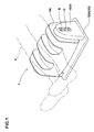
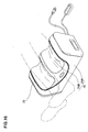
- Fig. 1 is a perspective view illustrating a state where a massage apparatus 1 is being used.
- Fig. 2 is a longitudinal sectional view of the massage apparatus 1.
- Fig. 3 is a plane view illustrating an internal structure of the massage apparatus 1.
- the massage apparatus 1 according to the present invention comprises a massage means 8 for pressing the user's massage parts and moving means 9 for reciprocating the massage means 8.
- the present embodiment shows an example of the massage means 8, which comprises massage bodies 7, a rotation shaft 3 for supporting the massage bodies 7, a drive unit 2, and support frames 18. Further, the support frame 18 according to the present embodiment comprises bearing tools 16 and a joint member 17.
- the bearing tools 16 according to the present embodiment have a shape of an upright rectangular thick plate and are provided with a support hole 32 comprising a bearing 31 in an approximate center thereof. A pair of the bearing tools 16 is disposed facing each other.
- the bearing tool 16 according to the present embodiment is formed from a steel stock having a horizontal width of, for example, approximately 60 to 90 mm, a vertical length of, for example, approximately 90 to 130 mm, and a thickness of, for example, approximately 15 to 22 mm.
- the joint member 17 is provided so as to bridge the bearing tools 16 and has an indented part 33 protruded downward in a center thereof.
- the joint member 17 has a mounting piece 34 rising at both ends thereof and fixedly fitting the bearing tools 16 in surfaces thereof facing each other.
- the joint member 17 according to the present embodiment is formed from, for example, a bent steel stock of approximately 1.2 to 2.3 mm.
- the rotation shaft 3 has a bar shape which horizontally extends and further has a circular shape in cross section. Both ends of the rotation shaft 3 are rotatably supported by the bearings 31 provided in the support holes 32 of the bearing tools 16.
- the rotation shaft 3 according to the present embodiment is formed from a round bar steel having a diameter of approximately 18 to 26 mm in the center thereof and a diameter of approximately 10 to 15 mm at both ends thereof.
- a length of the rotation shaft 3 in the present embodiment is, for example, approximately 460 mm.
- the drive unit 2 is disposed in the indented part 33 of the joint member 17 and further fixedly fitted to the joint member 17 by means of fitting tools 36.
- the drive unit 2 according to the present embodiment is preferable in that it is directly fixedly fitted to the joint member 17 to be stably supported.
- the drive unit 2 applies a rotational force to the rotation shaft 3 by having a drive axis 2A thereof combined with an approximate center of the rotation shaft 3 via a deceleration unit 35.
- the drive unit 2 according to the present embodiment is constituted in such manner as movable in synchronization with the rotation shaft 3 via the bearing tools 16 and the joint member 17 while applying the rotational force to the rotation shaft 3.
- the drive unit 2 is composed of an AC motor. Further, the drive unit 2 is connected to a 100V power supply for household use via an on/off switch S and a controller C including a motor rotation control circuit shown in Fig. 1, wherein a rotation of the motor is thereby controlled.
- the motor rotation control circuit controls the number of rotations of the motor and normal/reverse rotations of the motor, and is further capable of gradually increasing/decreasing the number of rotations by means of a microcomputer in accordance with waveforms programmed therein.
- the massage bodies 7, which are mounted on the rotation shaft 3, each comprise a cylindrical body 11, pressing boards 12, and tilting means 13.
- the cylindrical body 11 is composed of a pair of support boards 37 and a pressing rod 38 bridged over the support boards 37.
- the support boards 37 have a disk shape whose diameter is, for example, approximately 70 to 110 mm.
- the rotation shaft 3 is inserted into boss parts 37A provided in the center of the support boards 37.
- the support boards 37 are non-rotatably mounted on the rotation shaft 3 by means of a key, which is not shown, provided in a key groove 39 of the rotation shaft 3.
- the pressing rod 38 has a plurality of projected pressing parts 6 in an outer periphery thereof.
- the plurality of pressing parts 6 (six in the present embodiment) are equally spaced in an identical peripheral surface centered around the rotation shaft 3. Both ends of the pressing rod 38 are fixedly fitted to the support boards 37 by means of small screws.
- the pressing rod 38 according to the present embodiment is composed of a combined plurality of small cylinders 38A having projected pressing parts 6.
- the projected pressing parts 6 of the pressing rod 38 adjacent to one another are disposed in a houndstooth manner in order to disperse pressure applied to a massage part 4.
- a pair of the cylindrical bodies 11 are disposed in the rotation shaft 3 with an interval of, for example, approximately 160 to 230 mm provided therebetween, as shown in Fig. 3.
- the projected pressing parts 6 of the cylindrical body 11, which rotates in conjunction with the rotation shaft 3, press and stimulate the user's massage part 4 such as sole, thigh, or arm, as shown in Fig. 5, thereby exerting a massage effect.
- the rotational direction of the cylindrical bodies 11 may be changed in response to the control of the normal/reverse rotations of the drive unit 2 to thereby further enhance the massage effect.
- Sheet bodies 5 formed from felt, leather, or the like, are provided between the massage parts 4 and the cylindrical bodies 11 in order to ease the stimulation with respect to the massage parts 4.
- the pressing boards 12 in the present embodiment each have an approximate donut shape comprising an external board 12A, an internal board 12B, and a cover 12C, and are provided on both sides of the cylindrical body 11 so as to face each other.
- the external board 12A has an approximate ring shape and is fitted to an outer side of the internal board 12B.
- a flange 42 extending from an inner peripheral part toward an inner side of the external board 12A is fixedly fitted to the internal board 12B by means of a fitting tool 43, and the external board 12A and the internal board 12B are thereby formed as a unit.
- the cover 12C covers the surfaces of the external board 12A facing each other, and an inner peripheral part of the cover 12C is sandwiched by the external board 12A and the internal board 12B.
- the tiling hub 41 is formed in the manner that the outer peripheral surface 41A thereof is tilted at ⁇ degrees (for example, approximately 6 to 10 degrees) with respect to a central line X of the rotation shaft 3.
- a pair of the tilting hubs 41 sandwich the cylindrical body 11 and is non-rotatably mounted on the rotation shaft 3 by means of the key, which is not shown, provided in the key groove 39 in the state where the outer peripheral surfaces 41A thereof are tilted in reverse directions relative to each other.
- the tiling bearings 14 of the present embodiment are formed from bearings 14A and mounted on the outer peripheral surfaces 41A of the tilting hubs 41.
- the internal boards 12B of the pressing boards 12 are rotatably supported by the bearings 14A. Therefore, a pair of the bearings 14A disposed so as to sandwich the cylindrical body 11 are tilted at ⁇ degrees in the reverse directions relative to each other with respect to the central line X of the rotation shaft 3.
- a pair of the pressing boards 12 mounted on the bearings 14A are tilted through ⁇ degrees in the reverse directions relative to each other with respect to the central line X of the rotation shaft 3 and rotatably supported.
- the facing pressing boards 12 are allowed to rotate relative to each other with respect to the rotation shaft 3 and are repeatedly tilted reverse to each other. A distance between the pressing parts 6 facing each other is thereby periodically increased and decreased.
- the pressing boards 12 constituted in the foregoing manner are preferable in that the smooth tiling can be achieved and the structure required for the tilting can be simplified.
- the tilting receiving piece 15 constitutes the tilting means 13 for repeatedly tiling the pressing boards 12 in the reverse directions to thereby perform the massage.
- the cylindrical body 11 and the tilting means 13 supported by the rotation shaft 3 are sandwiched by a pair of fixing boards 45 fixedly fitted to the rotation shaft 3 by means of fitting tools 44 and thereby non-movably fixed in an axial direction of the rotation shaft 3.
- the massage body 7 may be formed from only the cylindrical body 11, or only the pressing boards 12 and the tilting means 13 without the cylindrical body 11.
- the moving means 9 for reciprocating the massage means 8 comprises a guiding tool 19, a crank arm 20, and a vertical guide fitting 23, and is provided in a box body 10 in the present embodiment.
- the moving means 9 constitutes a reciprocating means 27 for reciprocating the bearing tools 16 in the moving direction.
- the box body 10 of the present embodiment comprises side parts 10A disposed in the neighborhood of the both ends of the rotation shaft 3 and a combining part 10B for combining the side parts 10A.
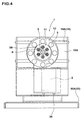
- the side part 10A of the present embodiment comprises, as shown in Fig. 6, a pedestal 24, a leg part 25 provided to the pedestal 24 in the standing manner, and sleeve parts 46 formed from both sides of the leg part 25 bent inward by 90 degrees.
- the guiding tool 19 of the present embodiment is composed of a pair of slide shafts 19A having a shape of a horizontal round bar vertically bridged over the sleeve parts 46 of the box body 10.
- An end of the slide shaft 19A is fixedly fitted by means of a fitting tool 48 penetrated through the sleeve part 46.
- the slide shafts 19A are respectively penetrated through slide holes 16A provided in the bearing tools 16 to thereby slidably support the bearing tools 16.
- the massage means 8 can be thereby smoothly reciprocated.
- the slide hole 16A has a bush 47 fitted thereto in order to increase the slidability with respect to the slide shaft 19A.
- crank arm 20 has a guiding body 21 in another end of thereof.
- the guiding body 21 of the present embodiment comprises a support shaft 52 extending in parallel with the rotation shaft 3 and a roll 53 rotatably supported by the support shaft 52.
- the crank arm 20 is formed so that a length thereof extending from a pivoting point with respect to the rotation shaft 3 to the guiding body 21 is, for example, 40 to 90 mm, and 65 mm in the present embodiment.
- the vertical guide fitting 23 comprises a substrate 23A having a shape of an upright rectangular plate, side pieces 23B formed from both ends of the substrate 23A bent by 90 degrees in the same direction, an upper piece 23C and a lower piece 23D formed from upper and lower ends of the substrate 23A bent by 90 degrees and serving to connect upper and lower ends of the side pieces 23B, and a pair of guide pieces 23E vertically extending between the upper piece 23C and the lower piece 23D inward of the side pieces 23B.
- the vertical guide fitting 23 is fixedly fitted to the leg part 25 of the box body 10 by means of a fitting tool 54 screwed into the substrate 23A between the side piece 23B and the guide piece 23E.
- the vertical guide fitting 23 is preferable in that it is directly stably fitted to the box body 10 and does not require any additional fitting tool to be interposed because of the direct fitting to the box body 10, thereby being reduced in size.
- the pair of guide pieces 23E movably guides the roll 53 fitted with a play therebetween in the vertical direction to thereby constitute the guiding part 22.
- the crank arm 20 is formed so that the length thereof extending from the pivoting point with respect to the rotation shaft 3 to the guiding body 21 is, as described, 40 to 90 mm (65 mm in the present embodiment), the stroke of the reciprocation is arranged to be 80 to 180 mm, preferably 100 to 160 mm, and 130 mm in the present embodiment.
- the stroke is less than 80 mm, the massage is given in too a small range. Therefore, the massage effect is reduced because the user feels unsatisfied getting used to the pressing and stimulation too soon.
- the stroke exceeds 180 mm, it is rather awkward to use the massage apparatus because the massage is given beyond a range to be massaged in sole, thigh, arm, or the like.
- the number of reciprocations of the massage body 7, which is controlled by the rotation number control implemented by the drive unit 2 and the deceleration ratio of the deceleration unit 35, is desirably set to 20 to 90 times/min, and more desirably to 30 to 65 time/min. In the present embodiment, the number of reciprocations is set to three stages of 30, 45, and 60 times/min.
- the number of reciprocations of the massage body 7 is less than 20 times/min, the moving speed of the massage body 7 is too slow, which results in a lowered massage effect because of the user's dissatisfaction for the pressing and stimulation.
- the number of reciprocations of the massage body 7 exceeds 90 time/min, the massage body 7 moves too fast, which reduces the massage effect obtained from the pressing and stimulation applied by the pressing parts 6.
- FIGs. 9 and 10 show another embodiment of the present embodiment. Any component, which is identical to those recited in the previous embodiment, is not described in the present embodiment and simply provided with the same reference symbols.
- a drive unit 2 according to the present embodiment is combined with the rotation shaft 3 via the deceleration unit 35 and thereby moves in conjunction with the movement in the moving direction orthogonal to the rotational central line of the rotation shaft 3.
- the drive unit 2 is slidably supported in the moving direction by a retaining body 26 having a short cylindrical shape and provided in the standing manner in the substrate 55A of the box body 10.
- the retaining body 26 comprises a bush (not shown) in an inner peripheral surface thereof and fixed to the substrate 55A by means of a fixing tool 57.
- the fixing tool 57 has an angle shape comprising a substrate 57A and a rising plate 57B bent upward from an end portion of the substrate 57A.
- the substrate 57A is fixedly fitted to the substrate 55A by means of a fitting tool 58, and fits the retaining body 26 to a mounting hole of the rising plate 57B.
- the drive unit 2 according to the present embodiment is preferable in that the massage means 8 is smoothly reciprocated because the drive unit 2 is supported so as to move in the moving direction by the retaining body 26 provided in the standing manner in the box body 10.
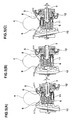
- the drive unit 2 guided by the retaining body 26 moves in response to the movement of the rotation shaft 3. More specifically, when the rotation shaft 3 is in the center position as shown in Fig. 7(A), the drive unit 2 is likewise in the center position as shown in Fig. 11(A).
- the crank arm 20 is rotated through 90 degrees to the right until it is disposed in the horizontal position and the rotation shaft 3 thereby moves by d1 to the left from the center position as shown in Fig. 7(B), the drive unit 2, in conjunction with the movement, is guided by the retaining body 26 to thereby move by d1 to the left, as shown in Fig. 11(B).
- FIGs. 12 and 13 show still another embodiment of the present embodiment.
- a frame 59 having a reverse U-letter shape for covering the drive unit 2 is mounted on the box body 10 in a center thereof.
- An outer peripheral part of the frame 59 is coated with a cushion layer 60 in order to protect the user's massage part 4.
- the cushion layer 60 is formed from sponge such as urethane form or polyethylene form, olefin-based or styrene-based thermoplastic elastomer, synthetic rubber such as styrene butadiene rubber or chloroprene rubber, or other material.
- Resin caps 61 having a curved shape are mounted on the side parts 10A of the box body 10 in order to prevent edge parts of the side parts 10A from damaging the user's massage part 4.
- the resin cap 61 is formed from a plastic material such as polyethylene, polypropylen, or polystylene.
- the massage body 7 and the cushion layer 60 are covered with the sheet body 5 formed from felt, leather, or the like.
- the stand 55 supporting the box body 10 comprises a bent leg 62 and a combining rod 63 as shown in Fig. 13.
- the bent leg 62 comprises a horizontal support rod 62A, a tilting rod 62B bent and tilted downward from one end of the support rod 62A, and a disposing rod 62C further bent in the same direction below the tilting rod 62B and extending in parallel with the support rod 62A, and has an approximate U-letter shape.
- the combining rod 63 connects end portions of the disposing rods 62C of the bent legs 62 disposed with an interval therebetween.
- a support part 64 is formed in the support rods 62A of the stand 55.
- the support part 64 supports the side parts 10A of the box body 10.
- the stand 55 according to the present embodiment is preferable in that a pair of the bent legs 62 and the combining rod 63 are continuous to thereby form a frame shape, thereby achieving a reduced weight and stable support.
- the present embodiment shows as an example of the support part 64, which comprises a pivoting means for oscillatably supporting the side part 10A and a fixing means 66 for fixing an angle of the pivoting.
- the pivoting means 65 comprises a support substrate 65A fixedly fitted to the support rod 62A and a pivoting shaft 65B formed in a protruding manner in the leg part 25 of the side part 10A.
- the support substrate 65A comprises a substrate main body 65A1 having an upright rectangular shape, and flanges 65A2 formed from upper and lower ends of the substrate main body 65A1 bent by 90 degrees.
- the lower flange 65A2 is welded on the support rod 62A, and the support substrate 65A is thereby fixedly fitted to the support rod 62A.
- a bush 67 capable of supporting the rotation shaft in a surface contact is fitted and fixed to the center of the support substrate 65A.
- the pivoting shaft 65B has a guiding shaft part 65B1 formed so as to have a larger diameter in an edge thereof, and the guiding shaft part 65B1 is rotatably inserted into the bush 67. As a result, the box body 10 is supported so as to rotate around the pivoting shaft 65B.
- the fixing means 66 comprises a to-be-engaged part 66A provided in the pivoting shaft 65B and an engaging means 66B engaged with the to-be-engaged part 66A and disabling the rotation of the pivoting shaft 65B.
- the to-be-engaged part 66A according to the present embodiment is formed from a plurality of indented parts 74 circumferentially provided with intervals therebetween in a peripheral surface of the guiding shaft part 65B1.
- the indented parts 74 are spaced at a pitch of approximately 15 to 30 degrees with respect to a central line of the pivoting shaft 65B, and at the pitch of 22.5 degrees in the present embodiment.
- the engaging means 66B according to the embodiment comprises an operation lever 68, a through hole 69 formed in a lower part of the bush 67, and an engaging ball 70 movable in the through hole 69.
- the operation lever 68 comprises a curved part 68A whose one end is oscillatably fitted to a lower part of the support substrate 65A by means of a pin 71 and formed along an outer periphery of the bush 67 and a grip part 68B bent outward from another end of the curved part 68A.
- a pull spring 72 for energizing the curved part 68A toward the bush 67 is mounted on the another end of the curved part 68A.
- An inner surface of the curved part 68A is provided with a protruding piece 73, whose edge is inserted into the through hole 69 to thereby press the engaging ball 70.
- the indented parts 74 are formed in a size capable of fitting an approximate half of the engaging ball 70. Therefore, the engaging ball 70 pressed by the protruding piece 73 energized by the pull spring 72 is retained in a position between the through hole 69 of the bush 67 and the indented parts 74 of the pivoting shaft 65B. As a result, the engaging ball 70 prevents the rotation of the pivoting shaft 65B.
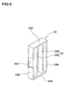
- FIGs. 16 and 17 show still another embodiment of the present invention.
- a box body according to the present embodiment is entirely covered with a dressing cover 75.
- the dressing cover 75 comprises a cover base part 75A covering a lower part of the box body 10 and an upper cover 75B covering an upper part of the massage body 7.
- the upper cover 75B is mounted on the cover base part 75A by means of a fastener 76 so as to open and close.
- the upper cover 75B is made from a thin and flexible fabric, a resin sheet, or the like so that the movement and pressure of the massage body 7 can be directly conveyed to the massage part.
- the box body 10 is used being directly disposed on a floor surface instead of being supported by the stand, as shown in Fig. 16. In the foregoing manner, the massage can be given in a stable state, and an entire body of the apparatus can be constituted in a compact size.
- a pair of pressing boards 12 supported as tilted in the reverse directions relative to each other with respect to the rotation shaft 3 by means of the tiling bearings 14 each comprise an internal board 12B rotatably fitted to the tiling bearing 14 and an external board 12A having a ring shape and fitted to an outer side of the internal board 12B.
- On surfaces of the external boards 12A facing each other are formed pressing parts 6 having a smooth and annular surface.
- the pressing parts 6 according to the present embodiment are smooth having no uneven part. Therefore, when the pressing parts 6 are rotated, a friction generated with respect to the dressing cover 75 can be reduced, and the pressing parts 6 can be prevented from being hooked on the massage part, thus achieving a smooth operation.
- the external board 12A is formed from an elastic material exemplified by styrene-butadiene rubber, chloroprene rubber, other synthetic rubber olefin-based/ styrene-based/ urethane-based thermoplastic elastomer, or the like. Further, as shown in Fig. 19, indentations 77 can be circumferentially formed with intervals therebetween in the pressing parts 6 of the pressing boards 12, which is preferable in that the massage effect can be enhanced because the indentations 77 generate a variation in pressing the massage part.
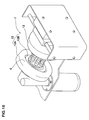
- FIG. 20 shows still another embodiment of the present invention.
- moving means 9 each comprise a vertical guide fitting 23 and a circular eccentric cam 78.
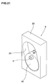
- a guiding part 22 having a shape of a vertically longer indentation whose vertical central line is tilted with respect to perpendicularity in the vertical guide fitting 23.
- the circular eccentric cam 78 is fixedly fitted to the end part of the rotation shaft 3 and inserted into the guiding part 22.
- the circular eccentric cam 78 rotating integrally with the rotation shaft 3 slides in contact with an inner peripheral surface of the tilted guiding part 22 to be thereby guided.
- the rotation shaft 3 supported by the bearing tools 16 is reciprocated in the direction orthogonal to the central line thereof.
- FIG. 23 shows still another embodiment of the present invention.
- a moving means 9 according to the present embodiment comprises a guiding tool 19, a crank arm 20, and a lever 28.
- the guiding tool 19, which is constituted in the substantially same manner as in the previous embodiment, comprises a pair of slide shafts 19A having a shape of a horizontal round bar and vertically bridged over the box body 10.
- the slide shafts 19A are respectively penetrated through the slide holes 16A formed on the bearing tools 16 to thereby slidably support the bearing tools 16, wherein the massage means 8 can be movably supported in the same manner as described in the previous embodiment.
- the crank arm 20 has a straight-bar shape, and an end thereof is fixed to an end part of a rotation shaft 3 rotatably supported by the bearing tools 16.
- the rotation shaft 3 according to the present embodiment is provided with chamfered square shaft parts 79 formed at the end parts thereof protruding from the bearing tools 16. The end of the crank arm 20 is fitted into the square shaft part 79 so that the crank arm 20 is fixed to the rotation shaft 3.
- the lever 28 has the straight-bar shape in the same manner as the crank arm 20, and an end thereof is supported by the box body 10.
- the lever 28 is oscillatably supported by means of a receiving tool 80 comprised of a substrate 80A and a receiving shaft 80B provided in the substrate in a protruding manner. More specifically, the end of the lever 28 is engaged with the receiving shaft 80B of the receiving tool 80, the substrate 80A of which is fixed to the leg part 25 of the box body 10, by means of a fitting tool 81 via a bearing 82.
- the rotation shaft 3 which is supported by the moving means 9 including the guiding tools 19, crank arms 20, and levers 28, repeatedly reciprocates in the direction orthogonal to its rotational central line. Therefore, the massage bodies 7 provided in the rotation shaft 3 press and stimulate the different massage parts 4 in turn, thereby providing an effective massage effect.
- the moving means 9 according to the present embodiment constitutes the linkage device substantially having the slider crank mechanism, wherein the crank arm 20 and the lever 28 are rotated in liaison with each other. Because of the constitution, the reciprocation of the massage means 8 can be smooth and noiseless. Besides, the stroke of the reciprocation can be easily enlarged when the linkage lengths of the crank arm 20 and the lever 28 are changed.
Landscapes
- Health & Medical Sciences (AREA)
- Epidemiology (AREA)
- Pain & Pain Management (AREA)
- Physical Education & Sports Medicine (AREA)
- Rehabilitation Therapy (AREA)
- Life Sciences & Earth Sciences (AREA)
- Animal Behavior & Ethology (AREA)
- General Health & Medical Sciences (AREA)
- Public Health (AREA)
- Veterinary Medicine (AREA)
- Massaging Devices (AREA)
Applications Claiming Priority (6)
| Application Number | Priority Date | Filing Date | Title |
|---|---|---|---|
| JP2003378767 | 2003-11-07 | ||
| JP2003378767 | 2003-11-07 | ||
| JP2004248806 | 2004-08-27 | ||
| JP2004248806 | 2004-08-27 | ||
| JP2004294095A JP2006087846A (ja) | 2003-11-07 | 2004-10-06 | マッサージ装置 |
| JP2004294095 | 2004-10-06 |
Publications (1)
| Publication Number | Publication Date |
|---|---|
| EP1530960A1 true EP1530960A1 (fr) | 2005-05-18 |
Family
ID=34437606
Family Applications (1)
| Application Number | Title | Priority Date | Filing Date |
|---|---|---|---|
| EP04025194A Withdrawn EP1530960A1 (fr) | 2003-11-07 | 2004-10-22 | Dispositif de massage |
Country Status (4)
| Country | Link |
|---|---|
| US (1) | US20050137502A1 (fr) |
| EP (1) | EP1530960A1 (fr) |
| JP (1) | JP2006087846A (fr) |
| KR (1) | KR20050044272A (fr) |
Cited By (2)
| Publication number | Priority date | Publication date | Assignee | Title |
|---|---|---|---|---|
| CN110575389A (zh) * | 2019-10-10 | 2019-12-17 | 河南省中医院(河南中医药大学第二附属医院) | 颈椎康复治疗装置 |
| CN110812196A (zh) * | 2019-11-13 | 2020-02-21 | 青岛大学附属医院 | 一种眼科可调节穴位力度的按摩装置 |
Families Citing this family (19)
| Publication number | Priority date | Publication date | Assignee | Title |
|---|---|---|---|---|
| US20070010767A1 (en) * | 2005-07-07 | 2007-01-11 | Kuang Yu Metal Working Co., Ltd. | Multidirectional oscillating device for a massage device |
| JP5200063B2 (ja) * | 2009-11-16 | 2013-05-15 | 大東電機工業株式会社 | マッサージ機 |
| JP2012110621A (ja) * | 2010-11-26 | 2012-06-14 | Shiseido Co Ltd | 手動マッサージ装置及びこれを用いた美容方法 |
| CN104434499B (zh) * | 2014-11-26 | 2017-04-26 | 厦门蒙发利科技(集团)股份有限公司 | 一种下肢按摩机 |
| CN104800060B (zh) * | 2015-04-23 | 2017-05-10 | 刘万坤 | 一种按摩仪 |
| CN104905953B (zh) * | 2015-04-23 | 2017-05-10 | 刘万坤 | 一种按摩装置 |
| CN110269790A (zh) * | 2018-03-16 | 2019-09-24 | 香港中文大学 | 用于关节窝的可穿戴理疗仪 |
| TWI694820B (zh) | 2018-12-28 | 2020-06-01 | 巫東和 | 鐘擺式下肢按摩機構(二) |
| TWI686188B (zh) * | 2018-12-28 | 2020-03-01 | 巫東和 | 按摩滾輪結構 |
| TWI694819B (zh) | 2018-12-28 | 2020-06-01 | 巫東和 | 鐘擺式下肢按摩機構 |
| KR200494009Y1 (ko) | 2019-06-25 | 2021-07-15 | 피트웰 인터내셔널 컴퍼니 리미티드 | 핸드 헬드형 진동 안마기 |
| USD945635S1 (en) * | 2019-12-31 | 2022-03-08 | Zeming Wang | Foot massager |
| USD917713S1 (en) * | 2020-01-10 | 2021-04-27 | Zhejiang Rifeng Electric Appliance CO. LTD | Massager |
| USD949382S1 (en) * | 2020-01-10 | 2022-04-19 | Zhejiang Rifeng Electric Appliance CO. LTD | Massager |
| USD948066S1 (en) * | 2021-03-26 | 2022-04-05 | Nekteck, Inc | Foot massager |
| USD1018878S1 (en) * | 2021-06-30 | 2024-03-19 | Zhejiang Simon Industry & Trade Co., Ltd. | Swing machine |
| USD1017059S1 (en) * | 2021-11-22 | 2024-03-05 | Weifeng ZHOU | Massager |
| USD1015556S1 (en) * | 2021-11-22 | 2024-02-20 | Weifeng ZHOU | Massager |
| USD1004792S1 (en) * | 2021-11-22 | 2023-11-14 | Weifeng ZHOU | Massager |
Citations (4)
| Publication number | Priority date | Publication date | Assignee | Title |
|---|---|---|---|---|
| FR1335549A (fr) * | 1962-07-02 | 1963-08-23 | Appareil de massage et de traitement | |
| EP1000600A1 (fr) * | 1998-05-07 | 2000-05-17 | Daito Electric Machine Industry Company Limited | Mecanisme de massage a rouleaux et dispositif de massage comportant ce mecanisme |
| US6599261B1 (en) * | 2002-01-23 | 2003-07-29 | Hsin Hao Health Materials Co., Ltd. | Massaging device |
| EP1382320A1 (fr) * | 2002-06-24 | 2004-01-21 | Motion S.r.l. | Lit masseur à configuration variable |
Family Cites Families (1)
| Publication number | Priority date | Publication date | Assignee | Title |
|---|---|---|---|---|
| JP2003190242A (ja) * | 2001-12-26 | 2003-07-08 | Sanyo Electric Co Ltd | マッサージアッセンブリ及びこれを搭載したマッサージ機 |
-
2004
- 2004-10-06 JP JP2004294095A patent/JP2006087846A/ja active Pending
- 2004-10-21 US US10/968,911 patent/US20050137502A1/en not_active Abandoned
- 2004-10-22 EP EP04025194A patent/EP1530960A1/fr not_active Withdrawn
- 2004-11-05 KR KR1020040089595A patent/KR20050044272A/ko not_active Application Discontinuation
Patent Citations (4)
| Publication number | Priority date | Publication date | Assignee | Title |
|---|---|---|---|---|
| FR1335549A (fr) * | 1962-07-02 | 1963-08-23 | Appareil de massage et de traitement | |
| EP1000600A1 (fr) * | 1998-05-07 | 2000-05-17 | Daito Electric Machine Industry Company Limited | Mecanisme de massage a rouleaux et dispositif de massage comportant ce mecanisme |
| US6599261B1 (en) * | 2002-01-23 | 2003-07-29 | Hsin Hao Health Materials Co., Ltd. | Massaging device |
| EP1382320A1 (fr) * | 2002-06-24 | 2004-01-21 | Motion S.r.l. | Lit masseur à configuration variable |
Cited By (3)
| Publication number | Priority date | Publication date | Assignee | Title |
|---|---|---|---|---|
| CN110575389A (zh) * | 2019-10-10 | 2019-12-17 | 河南省中医院(河南中医药大学第二附属医院) | 颈椎康复治疗装置 |
| CN110812196A (zh) * | 2019-11-13 | 2020-02-21 | 青岛大学附属医院 | 一种眼科可调节穴位力度的按摩装置 |
| CN110812196B (zh) * | 2019-11-13 | 2021-07-23 | 青岛大学附属医院 | 一种眼科可调节穴位力度的按摩装置 |
Also Published As
| Publication number | Publication date |
|---|---|
| JP2006087846A (ja) | 2006-04-06 |
| US20050137502A1 (en) | 2005-06-23 |
| KR20050044272A (ko) | 2005-05-12 |
Similar Documents
| Publication | Publication Date | Title |
|---|---|---|
| EP1530960A1 (fr) | Dispositif de massage | |
| KR0159035B1 (ko) | 침대 | |
| US7022092B2 (en) | Four massaging head type massaging mechanism and massaging apparatus incorporating the same | |
| EP1000600A1 (fr) | Mecanisme de massage a rouleaux et dispositif de massage comportant ce mecanisme | |
| US20060211962A1 (en) | Portable body massager | |
| US20220079835A1 (en) | Vertical Massage Device and Method of Use | |
| US8192378B2 (en) | Toe massage device | |
| JP2003310689A (ja) | 可搬型マッサージ機 | |
| CA2113487A1 (fr) | Chaise avec dispositif de massage a action cyclique | |
| WO2008036955A2 (fr) | Dispositif de massage robotisé permettant le pétrissage et le pincer-rouler | |
| KR20120130808A (ko) | 기능성 의자 | |
| JP4223839B2 (ja) | 4つ玉式マッサージ機構とこの機構を内蔵したマッサージ装置 | |
| JP5593298B2 (ja) | マッサージ機 | |
| JP2003000665A (ja) | 下肢用マッサージ機とこのマッサージ機を用いた椅子型マッサージ装置 | |
| KR20220123611A (ko) | 방향전환이 가능한 회전형 안마의자 | |
| JP3046804B2 (ja) | ローラマッサージ機 | |
| JPH0753621Y2 (ja) | マッサ−ジ装置 | |
| JP2005080782A (ja) | 下肢用マッサージ機とこのマッサージ機を用いた椅子型マッサージ装置 | |
| JPH022351Y2 (fr) | ||
| WO2007117071A1 (fr) | Appareil de traitement de troubles du cou | |
| JPH0130182Y2 (fr) | ||
| WO2021117284A1 (fr) | Dispositif de massage de membre inférieur | |
| KR100469227B1 (ko) | 다리베개 기능을 갖는 의자 | |
| JPH08308900A (ja) | マッサージ機 | |
| JPS6130680Y2 (fr) |
Legal Events
| Date | Code | Title | Description |
|---|---|---|---|
| PUAI | Public reference made under article 153(3) epc to a published international application that has entered the european phase |
Free format text: ORIGINAL CODE: 0009012 |
|
| AK | Designated contracting states |
Kind code of ref document: A1 Designated state(s): AT BE BG CH CY CZ DE DK EE ES FI FR GB GR HU IE IT LI LU MC NL PL PT RO SE SI SK TR |
|
| AX | Request for extension of the european patent |
Extension state: AL HR LT LV MK |
|
| 17P | Request for examination filed |
Effective date: 20051114 |
|
| AKX | Designation fees paid |
Designated state(s): DE FR GB IT |
|
| STAA | Information on the status of an ep patent application or granted ep patent |
Free format text: STATUS: THE APPLICATION IS DEEMED TO BE WITHDRAWN |
|
| 18D | Application deemed to be withdrawn |
Effective date: 20080503 |