EP1530322A2 - Konfiguration eines Verschlüsselungsschlüssels im WLAN Zugangspunkt und im Terminal - Google Patents
Konfiguration eines Verschlüsselungsschlüssels im WLAN Zugangspunkt und im Terminal Download PDFInfo
- Publication number
- EP1530322A2 EP1530322A2 EP04256869A EP04256869A EP1530322A2 EP 1530322 A2 EP1530322 A2 EP 1530322A2 EP 04256869 A EP04256869 A EP 04256869A EP 04256869 A EP04256869 A EP 04256869A EP 1530322 A2 EP1530322 A2 EP 1530322A2
- Authority
- EP
- European Patent Office
- Prior art keywords
- terminal
- access point
- encryption key
- data
- connection
- Prior art date
- Legal status (The legal status is an assumption and is not a legal conclusion. Google has not performed a legal analysis and makes no representation as to the accuracy of the status listed.)
- Granted
Links
Images


Classifications
-
- H—ELECTRICITY
- H04—ELECTRIC COMMUNICATION TECHNIQUE
- H04W—WIRELESS COMMUNICATION NETWORKS
- H04W12/00—Security arrangements; Authentication; Protecting privacy or anonymity
- H04W12/02—Protecting privacy or anonymity, e.g. protecting personally identifiable information [PII]
-
- H—ELECTRICITY
- H04—ELECTRIC COMMUNICATION TECHNIQUE
- H04L—TRANSMISSION OF DIGITAL INFORMATION, e.g. TELEGRAPHIC COMMUNICATION
- H04L63/00—Network architectures or network communication protocols for network security
- H04L63/06—Network architectures or network communication protocols for network security for supporting key management in a packet data network
- H04L63/061—Network architectures or network communication protocols for network security for supporting key management in a packet data network for key exchange, e.g. in peer-to-peer networks
-
- H—ELECTRICITY
- H04—ELECTRIC COMMUNICATION TECHNIQUE
- H04L—TRANSMISSION OF DIGITAL INFORMATION, e.g. TELEGRAPHIC COMMUNICATION
- H04L63/00—Network architectures or network communication protocols for network security
- H04L63/20—Network architectures or network communication protocols for network security for managing network security; network security policies in general
-
- H—ELECTRICITY
- H04—ELECTRIC COMMUNICATION TECHNIQUE
- H04L—TRANSMISSION OF DIGITAL INFORMATION, e.g. TELEGRAPHIC COMMUNICATION
- H04L9/00—Cryptographic mechanisms or cryptographic arrangements for secret or secure communications; Network security protocols
- H04L9/08—Key distribution or management, e.g. generation, sharing or updating, of cryptographic keys or passwords
-
- H—ELECTRICITY
- H04—ELECTRIC COMMUNICATION TECHNIQUE
- H04W—WIRELESS COMMUNICATION NETWORKS
- H04W12/00—Security arrangements; Authentication; Protecting privacy or anonymity
- H04W12/03—Protecting confidentiality, e.g. by encryption
-
- H—ELECTRICITY
- H04—ELECTRIC COMMUNICATION TECHNIQUE
- H04W—WIRELESS COMMUNICATION NETWORKS
- H04W12/00—Security arrangements; Authentication; Protecting privacy or anonymity
- H04W12/04—Key management, e.g. using generic bootstrapping architecture [GBA]
-
- H—ELECTRICITY
- H04—ELECTRIC COMMUNICATION TECHNIQUE
- H04W—WIRELESS COMMUNICATION NETWORKS
- H04W12/00—Security arrangements; Authentication; Protecting privacy or anonymity
- H04W12/80—Arrangements enabling lawful interception [LI]
-
- H—ELECTRICITY
- H04—ELECTRIC COMMUNICATION TECHNIQUE
- H04L—TRANSMISSION OF DIGITAL INFORMATION, e.g. TELEGRAPHIC COMMUNICATION
- H04L63/00—Network architectures or network communication protocols for network security
- H04L63/04—Network architectures or network communication protocols for network security for providing a confidential data exchange among entities communicating through data packet networks
- H04L63/0428—Network architectures or network communication protocols for network security for providing a confidential data exchange among entities communicating through data packet networks wherein the data content is protected, e.g. by encrypting or encapsulating the payload
-
- H—ELECTRICITY
- H04—ELECTRIC COMMUNICATION TECHNIQUE
- H04W—WIRELESS COMMUNICATION NETWORKS
- H04W76/00—Connection management
- H04W76/10—Connection setup
-
- H—ELECTRICITY
- H04—ELECTRIC COMMUNICATION TECHNIQUE
- H04W—WIRELESS COMMUNICATION NETWORKS
- H04W84/00—Network topologies
- H04W84/02—Hierarchically pre-organised networks, e.g. paging networks, cellular networks, WLAN [Wireless Local Area Network] or WLL [Wireless Local Loop]
- H04W84/10—Small scale networks; Flat hierarchical networks
- H04W84/12—WLAN [Wireless Local Area Networks]
-
- H—ELECTRICITY
- H04—ELECTRIC COMMUNICATION TECHNIQUE
- H04W—WIRELESS COMMUNICATION NETWORKS
- H04W88/00—Devices specially adapted for wireless communication networks, e.g. terminals, base stations or access point devices
- H04W88/08—Access point devices
Definitions
- the present invention relates to a technology to configure in an access point and terminal an encryption key used to encode data transmitted wirelessly between the access point comprising a wireless LAN transponder and the terminal that includes a LAN connection device.
- Various wireless LAN security technologies that prevent unauthorized network access or leakage to third parties of the contents of communications have been proposed in the conventional art.
- a technology hereinafter referred to as 'MAC address restriction' technology
- a MAC (Media Access Control) address that constitutes a unique ID signal pre-assigned to a wireless LAN connection device (such as a wireless LAN adapter) installed in a terminal is registered with an access point, the access point authenticates the MAC address at the time of terminal access, and a request for network access from a terminal having a MAC address different from the registered MAC address is denied
- Japanese Patent Laid-Open No. 2001-320373 Japanese Patent Laid-Open No. 2001-320373
- 'WEP encoding' A technology (hereinafter referred to as 'WEP encoding') has also been proposed whereby a WEP (Wired Equivalent Privacy) key using a desired text string is registered as a common encryption key for both the terminal and the access point and the contents of data exchanged between the terminal and the access point are encrypted using this WEP key, such that even if the data leaks, the contents of the data are difficult to interpret and the data cannot be understood (see, for example, Japanese Patent Laid-Open No. 2001-345819) .
- WEP Wired Equivalent Privacy
- the newly proposed wireless LAN configuration method must incorporate sufficient measures to prevent the WEP key from leaking during the configuration process and to preserve the confidentiality of the terminal user's communications.
- an object of the present invention is to resolve some of the problems described above and enable required configuration operations when forming a wireless LAN to be carried out using a simple method while increasing security via the following construction.
- the access point of the present invention is an access point that connects to terminals to network through a wireless LAN connection device equipped on said terminals, said access point comprising:
- the above wireless LAN connection device is a device that is installed in a terminal in order to enable wireless communication between the terminal and an access point.
- An example of this wireless LAN communication device is a wireless LAN adapter or a wireless LAN card.
- examples of the terminal-specific information included in the initial configuration packet may include a MAC address, a CPU ID (processor serial number), a random number generated by the terminal, information regarding the time at which the terminal performed a prescribed operation, or a combination thereof.
- the access point of the present invention detects a status of a connection configuration required for connection to the network.
- the access point activates a restricted receiving mode in which only an initial configuration packet that contains terminal-specific information is accepted.
- the terminal identification unit identifies the first terminal that sent the initial configuration packet based on the terminal-specific information included therein, and prior to communication with the identified first terminal, the encryption key setting unit sets, using the terminal-specific information, an encryption key to be used for communications with the first terminal to a value corresponding to the encryption key set in the first terminal that sent the initial configuration packet.
- the owner of the first terminal can set in the first terminal and the access point the encryption key to be used therebetween by instructing from the first terminal that such initial configuration packet be sent.
- the first terminal and the access point need not have a wireless exchange of data regarding the encryption key to set such encryption key to be used therebetween, so there is no risk that the encryption key data will be obtained by a third party via interception of wireless radio waves. Therefore, an encryption key required for creation of a wireless LAN may be set easily while preventing the leakage of data pertaining to such encryption key.
- the above restricted receiving mode may comprise a mode in which the access point stands by for an initial configuration packet without issuing beacon signals used for position confirmation. This makes it difficult to ascertain the position of the access point. Therefore, the unauthorized interception of security data targeting the access point can be prevented.
- the access point of the present invention include display unit that provides a visual display that the restricted receiving mode is active. This allows the terminal owner to easily determine that the access point is in a state in which a wireless LAN can be formed.
- the access point of the present invention comprises a mode switching unit that, following the encryption key setting, switches the active mode from said restricted receiving mode to a wireless communication mode that said access point communicates with said first terminal; and a connection configuration unit that, following switching to said wireless communication mode, when connection configuration data pertaining to the settings for connection to the network is transmitted while encoded using the encryption key set in said first terminal, receives said connection configuration data, decodes said connection configuration data using the first encryption key set by said encryption key setting unit and configures the network connection for said first terminal based on the decoded connection configuration data.
- the network connection between the access point and the first terminal can be automatically configured following the setting of the encryption key.
- the network connection configuration data is transmitted wirelessly from the first terminal to the access point after being encoded using the previously-set encryption key valid between the first terminal and the access point, it is difficult for the connection configuration data to be interpreted via interception of the wireless radio waves. Therefore, the network connection configuration required for creation of the wireless LAN can be carried out easily with a high level of security.
- connection configuration data examples include information identifying the individual networks in the wireless LAN (such as ESS ID (Extended Service Set ID), the type of circuit to be connected to the WAN (Wide Area Network) (such as xDSL, CATV or optical fiber) or data indicating the contents of the contract with the ISP (hereinafter 'contract data').
- This contract data may comprise information identifying the computer on the WAN (such as the IP address used in the TCP/IP network), the user name used for authentication for connection to the WAN (as when PPPoE is used, for example), or password information.
- the access point of the present invention comprises an encoded data receiving unit that, following the setting of the first encryption key, when an initial configuration packet that includes a second information specific to a second terminal among said terminals is sent from said second terminal for which an encryption key used for communications with said access point has not yet been set, receives additional registration data that includes said second terminal-specific information for said second terminal is sent from said first terminal that received said initial configuration packet, after being encoded using the first encryption key that is already set and used for communications between said access point and said first terminal, receives this additional registration data; an additional terminal identification unit that decodes the received additional registration data using the encryption key set by said encryption key setting unit and identifies said second terminal that sent said initial configuration packet based on said second terminal-specific information included in the decoded additional registration data; and an additional setting unit that, prior to communication with said identified second terminal, sets a second encryption key to be used for communications with said second terminal to a value corresponding to an encryption key set in said second terminal using said terminal-specific.
- the owner of the second terminal can set in the access point and the second terminal an encryption key that will be used for communications therebetween simply by instructing the second terminal to send an initial configuration packet.
- the second terminal and the access point need not have a wireless exchange of data regarding the encryption key in order to set such encryption key to be used therebetween, so there is no risk that the encryption key data will be obtained by a third party via interception of the wireless radio waves. Therefore, even where a terminal to use a wireless LAN is newly added, an encryption key required for wireless LAN creation may be set easily while preventing the leakage of data pertaining to such encryption key.
- the access point of the present invention further comprises an additional connection configuration unit that, following the setting of the encryption key by said additional setting unit, when connection configuration data pertaining to the settings for connection to the network is sent from said second terminal after being encoded using the encryption key set in said second terminal, receives this connection configuration data, decodes said connection configuration data using the second encryption key set by said additional setting unit and executes the connection configuration for said second terminal based on the decoded connection configuration data.
- configuration regarding connection to the network can be carried out automatically between the access point and the second terminal following setting of the encryption key.
- connection configuration data pertaining to the network connection settings is sent wirelessly from the second terminal to the access point while encoded using the previously-set encryption key valid between the second terminal and the access point, it is difficult to interpret the connection configuration data via interception of the wireless radio waves. Therefore, even where a terminal to use a wireless LAN is newly added, the network connection configuration operations required to form a wireless LAN can be carried out easily with a high level of security.
- the access point includes storage unit that stores in advance a provisional key comprising an encryption key used to decode the encoded initial configuration packet, as well as information retrieval unit that, when the terminal identifying unit or additional terminal identifying unit receives an initial configuration packet from either the first or second terminal that is encoded by a temporary key, retrieves the terminal-specific information contained in the initial configuration packet by decoding the initial configuration packet using the stored provisional key.
- the initial configuration packet that includes the terminal-specific information is sent wirelessly to the access point from the first or second terminal while encoded using the temporary key, it is difficult to interpret the terminal-specific information via interception of the wireless radio waves. Therefore, unauthorized network access using the terminal-specific information for another person can be prevented.
- the value of the encryption key set by the encryption key setting unit or the additional setting unit be determined in association with the time at which the initial configuration packet was sent from the first or second terminal. In this case, it becomes extremely difficult to interpret the encryption key set in the access point and the first and second terminals, further increasing the degree of security of the wireless communications between the access point and each terminal.
- the present invention may comprise a terminal that includes a wireless LAN connection device and carries out wireless communication between such device and the above access point using wireless communication data encoded using a prescribed encryption key.
- This terminal comprises a transmission unit that wirelessly transmits an initial configuration packet that includes information specific to said terminal based on a prescribed instruction; and a setting unit that, prior to the exchange of data via wireless communication with said access point that receives said terminal-specific information included in said initial configuration packet sent by said transmission unit, sets the encryption key used for communications with said access point using said terminal-specific information. After transmission of the initial configuration packet, the terminal sets the encryption key in itself using the terminal-specific information included in the initial configuration packet.
- the access point-side encryption key is set to correspond to the encryption key set in the above manner, there is no need for a wireless exchange of encryption key data between the terminal and the access point in order to set the encryption key to be used between the terminal and the access point, thereby eliminating the risk that the encryption key data will leak to a third party via interception of the wireless radio waves.
- the encryption key configuration operations required for creation of a wireless LAN can be carried out easily while preventing the leakage of data that would reveal the encryption key.
- a construction also may be adopted wherein the transmission of an initial configuration packet by the transmission unit is executed when a prescribed program is booted on the terminal.
- the encryption key can be reliably set in the terminal and in the access point even where the terminal owner has only a limited understanding of networks.
- a first encryption key setting system of the present invention is implemented in the way of above described an access point and a terminal invention.
- An encryption key setting method that uses the technology of the first encryption key setting system described above may also be implemented.
- the terminal and the access point need not have a wireless exchange of data regarding the encryption key itself to be used therebetween, so there is no risk that the encryption key data will be obtained by a third party via interception of the wireless radio waves.
- the encryption key configuration operations required for creation of a wireless LAN can be carried out easily while preventing the leakage of data that would reveal the encryption key.
- first encryption key setting system and first encryption key setting method described above may be envisioned. While the encryption key setting system is described below as an example, the same embodiment may be implemented as an encryption key setting method. Naturally, the various embodiments of the invention pertaining to the access point described above may be applied to the invention pertaining to the encryption key setting system and encryption key setting method.
- the terminal comprises a connection configuration data transmission unit that, following setting of the encryption key by said setting unit, transmits connection configuration data pertaining to the settings for connection to the network after encoding said data using the encryption key set in said terminal.
- the access point comprises: a mode switching unit that, after the first encryption key is set by said encryption key setting unit, switches the active mode from said restricted receiving mode to a wireless communication mode in which said access point can communicate wirelessly with said terminal; and a connection configuration unit that, when connection configuration data transmitted from said first terminal is received following the switching to said wireless communication mode, decodes said connection configuration data using the encryption key and configures the network connection for said first terminal based on the decoded connection configuration data.
- the network connection between the access point and the terminal can be automatically configured following the setting of the encryption key. Furthermore, because the network connection configuration data is transmitted wirelessly from the terminal to the access point after being encoded using the previously-set encryption key valid between the terminal and the access point, it is difficult for the connection configuration data to be interpreted via interception of the wireless radio waves. Therefore, the network connection configuration operations required for creation of the wireless LAN can be carried out easily with a high level of security.
- terminals include a first terminal for which the first encryption key valid between said terminal and said access point is already set and a second terminal for which an encryption key valid between said terminal and said access point is not yet set.
- the first terminal further comprises: a packet receiving unit that receives an initial configuration packet that was sent from said second terminal and includes information specific to said second terminal; and an additional registration data transmission unit that, following the receipt of said initial configuration packet, transmits to said access point additional registration data that includes said information specific to said second terminal after encoding said data using the encryption key valid between said first terminal and said access point.
- the access point further comprises: an additional terminal identification unit that receives said additional registration data, decodes said data using the first encryption key, and identifies said second terminal that sent said initial configuration packet based on said terminal-specific information included in the decoded additional registration data; and an additional setting unit that, prior to communication with said identified second terminal, sets a second encryption key used for communications with said second terminal to a value corresponding to an encryption key set in said second terminal, using said second terminal-specific information.
- an additional terminal identification unit that receives said additional registration data, decodes said data using the first encryption key, and identifies said second terminal that sent said initial configuration packet based on said terminal-specific information included in the decoded additional registration data
- an additional setting unit that, prior to communication with said identified second terminal, sets a second encryption key used for communications with said second terminal to a value corresponding to an encryption key set in said second terminal, using said second terminal-specific information.
- the second terminal and the access point need not have a wireless exchange of data regarding the encryption key to be used therebetween, so there is no risk that the encryption key data will be obtained by a third party via interception of the wireless radio waves. Therefore, even where a terminal to use a wireless LAN is newly added, an encryption key required for creation of a wireless LAN may be set easily while preventing the leakage of data pertaining to such encryption key.
- the second terminal comprises an additional connection configuration data transmission unit that, after said additional setting unit in said second terminal sets the second encryption key for communication with said second terminal, transmits connection configuration data pertaining to the network connection settings while encoding the data using the encryption key set in said second terminal.
- the access point further comprises an additional connection configuration unit that receives said connection configuration data sent from said second terminal, decodes said connection configuration data using the second encryption key set by said additional setting unit and executes the connection configuration for said second terminal based on the decoded connection configuration data.
- configuration regarding connection to the network can be carried out automatically between the access point and the second terminal following setting of the encryption key.
- the network connection configuration data is sent wirelessly from the second terminal to the access point while encoded using the previously set encryption key valid between the second terminal and the access point, it is difficult to interpret the connection configuration data via interception of the wireless radio waves. Therefore, even where a terminal to use a wireless LAN is newly added, an encryption key required for creation of a wireless LAN may be set easily while preventing the leakage of data pertaining to such encryption key.
- the technology of the above invention can also be implemented as a program invention.
- the program of the present invention describes the operations performed by at least one of the access point and terminals in a format that can be read by a computer.
- the same operation and effects described above can be achieved via the loading and execution of this program on a computer that incorporates the access point or one of the terminals.
- the second encryption key setting system of the present invention is an encryption key setting system that sets in an access point that comprises a wireless LAN transponder and in a terminal that includes a wireless LAN connection device an encryption key used when wireless communication data that is exchanged wirelessly between the access point and the terminal is encoded prior to such data exchange.
- the system comprises an RFID tag that includes an RFID chip having a communication range that is narrower than the wireless communication range for the wireless communication data, and that stores information pertaining to the encryption key valid between said terminal and said access point; wherein said access point and said terminal each comprise: an information retrieval unit that retrieves the encryption key information stored in said RFID tag; and an setting unit that sets in its own device the encryption key valid between said terminal and said access point based on said information retrieved by said information retrieval unit.
- the second encryption key setting system of the present invention includes an RFID tag that comprises an RFID chip having a communication range that is smaller than the wireless communication range for the wireless communication data and stores information pertaining to the encryption key valid between the terminal and the access point.
- RFID Radio Frequency Identification
- RFID is a mechanism for carrying out identification of individual devices or items and data transmission and receipt by transmitting radio waves to an RFID tag comprising a chip containing an IC and an antenna and reading the information stored in the IC of the RFID tag.
- the encryption key data can be transmitted wirelessly within the small RFID communication range simply by placing an RFID tag in the small RFID communication range, and the encryption key can be set in the access point and the terminal via such transmission. Therefore, the wireless setting of the encryption key in the access point and the terminal can be achieved using the simple method of bringing the RFID tag close to the access point and the terminal, while maintaining a high level of security in order to prevent the leakage of the WEP key.
- Fig. 1 is an explanatory drawing showing the hardware construction to realize a wireless network configuration system GH1 comprising a first embodiment of the present invention
- Fig. 2 is an explanatory drawing showing the construction of an access point 20.
- the wireless network configuration system GH1 is a system to perform the configuration tasks needed to form a wireless LAN between the access point 20 and a terminal 50 (60), as well as the configuration tasks needed to enable the terminal 50 (60) to connect to a WAN (referred to in the preferred embodiments for realizing the invention in this Specification as the 'Internet IN').
- the latter tasks are referred to below as configuration for connection to the Internet IN.
- This system includes an encryption key setting system LH1 that, during formation of the wireless LAN, sets a WEP key to be valid between the access point 20 and the terminal 50 (60) positioned within the wireless communication range of the access point 20 (in the first embodiment, within the wireless communication area AR1) as an encryption key without wirelessly transmitting the key data indicating the contents of the WEP key over radio waves.
- LH1 an encryption key setting system LH1 that, during formation of the wireless LAN, sets a WEP key to be valid between the access point 20 and the terminal 50 (60) positioned within the wireless communication range of the access point 20 (in the first embodiment, within the wireless communication area AR1) as an encryption key without wirelessly transmitting the key data indicating the contents of the WEP key over radio waves.
- an access point 20 (wireless base station) comprising a wireless LAN transponder is disposed within the wireless communication area AR1.
- the access point 20 includes a CPU 11, a ROM 12 and a RAM 13 that are connected to the CPU 11 via a bidirectional bus, a nonvolatile storage device 14 such as a hard disk, a WAN port 17 that serves as a network interface, a LAN port 22 used for connecting to a wired LAN, a wireless communication interface 18, a display controller 15, an I/O controller 16, a timer 21 and other components, as shown in Fig. 2.
- a power switch that switches the supply of electric power to these components ON and OFF is disposed on the outside of the housing of the access point 20.
- a display lamp 19 that displays the current communication mode of the access point 20 (either restricted receiving mode or wireless communication mode) by turning ON or OFF is connected to the display controller 15. This display lamp 19 is disposed such that it is exposed on the housing surface of the access point 20.
- the timer 21 measures the time required for the execution of various processes and the time that has elapsed following the execution of the various operations. The results of such timekeeping are stored temporarily in the RAM 13.
- a transmitter 25 that transmits radio waves and a receiver 26 that receives radio waves are connected to the wireless communication interface 18.
- the transmitter 25 and receiver 26 are incorporated in the access point 20 to enable the external transmission of radio waves and the receipt of external radio waves.
- the range within which the radio waves transmitted from the transmitter 25 can be received and within which the receiver 26 can receive the radio waves from the terminal 50 (60) is expressed as the wireless communication area AR1.
- a router 28 that incorporates a modem is connected to the WAN port 17 via a cable.
- the router 28 can identify a terminal 50 (60) belonging to the wireless LAN and distinguish between multiple terminals based on the MAC address of the wireless LAN adapter 52 (62) described below.
- the modem in the router 28 is connected to the Internet IN via a broadband communication circuit CL such as a CATV circuit or xDSL circuit, or via a dedicated circuit supplied by the Internet service provider PV.
- the router functions as a gateway to connect the wireless LAN to the Internet IN.
- the terminal 50 (60) is a commonly used notebook personal computer, and includes a control device comprising a CPU, a ROM, a RAM, an internal clock and the like, as well as a hard disk that functions as a storage device, a display 53 (63) that functions as a display device, a trackball, a CD drive, a memory card drive, a USB port and the like.
- the internal clock keeps track of the times at which various operations are executed by the CPU. The results of such timekeeping are stored temporarily in the RAM 13.
- the terminal 50 (60) may also comprise a terminal other than a notebook personal computer, such as a PDA (Personal Digital Assistant).
- a wireless LAN adapter 52 (62) that functions as a wireless LAN connection device is disposed in the memory card drive of the terminal 50 (60) to enable the transmission and receipt of radio waves between such terminal and the access point. Incorporating the device driver for the wireless LAN adapter 52 (62) in the terminal 50 (60) enables the terminal 50 (60) to recognize and control the installed wireless LAN adapter 52 (62). Incidentally, a MAC address comprising an identification number unique to the adapter is assigned to the wireless LAN adapter 52 (62).
- a setup CD-ROM 51 to be inserted in the CD-ROM drive of the terminal 50 (60) is included as an accessory part to the wireless LAN adapter 52 (62) (see Fig. 3).
- the CD-ROM 51 stores an installation program for the device driver for the wireless LAN adapter 52 (62), security programs pertaining to the formation of a wireless LAN and to connecting to the Internet IN via the access point, as well as data necessary for the execution of such programs. Naturally, these programs and data may be stored on a recording medium other than the CD-ROM 51.
- the menu screen shown in Fig. 3 is automatically displayed on the display 53 (63). Two tabs entitled 'Configure this computer' and 'Configure another computer' are displayed such that they can be selected using the trackball.
- the MAC address of a terminal 50 (60) is registered with the access point 20, and a wireless LAN is formed between the terminal having a registered MAC address (referred to below as a 'registered terminal') and the access point 20.
- the terminal 50 (60) in the wireless communication area AR1 can communicate wirelessly with the access point 20 via the transmission and receipt of radio waves between the built-in wireless LAN adapter 52 (62) and the access point 20.
- the access point 20 and the wireless LAN adapter 52 (62) can convert the data that they exchange into a format suitable for data communication, i.e., into so-called packets.
- the settings governing connection to the Internet IN are configured in the terminal 50 (60) constituting a registered terminal and in the access point.
- the terminal 50 (60) within the wireless communication area AR1 can communicate with the Internet IN via wireless communication with the access point 20.
- data can be exchanged between the terminal 50 (60) and the access point 20 while the access point 20 is in an online state (i.e., where it is connected to the Internet).
- various information such as Web pages stored on a server SV connected to the Internet IN can be retrieved.
- the wireless communication area AR1 is a 'free spot' that provides a connection to the Internet only to owners of registered terminals.
- Data containing various types of content is sent and received over radio waves in an online or offline state.
- a device that sends content-containing data i.e., a registered terminal or the access point 20
- the receiving device decodes the received encoded data using the WEP key and retrieves the content-containing data.
- WEP is an encoding technology that is based on the private-key cryptography method used by the IEEE 802.11 standard (a method in which the same encryption key is used for encoding of data and decoding of the encoded data), and a 64-bit or 128-bit WEP key is used as the encryption key.
- this WEP key-based encoding makes it difficult to interpret the content-containing data, thereby preventing leakage of the transmitted content to a third party. For example, where a contract document that includes a credit card number is transmitted from a registered terminal to the access point 20, a third party can be prevented from obtaining the credit card number via interception of the transmitted radio waves.
- Fig. 4 is an explanatory drawing showing the contents of the programs and data stored in the ROM 12 of the access point 20 and in the CD-ROM 51 inserted in the terminal 50 (60).
- programs that describe the security data setting routines and the connection configuration routines, as well as data necessary to execute these programs are stored in the ROM 12 and on the CD-ROM 51.
- the security data setting routines are routines by which a wireless LAN is formed between the access point 20 and the terminal 50 (60) by registering the MAC address of the wireless LAN adapter 52 (62) in the access point 20 and setting the WEP key to be used between the access point 20 and the terminal 50 (60) in the access point 20 and the terminal 50 (60).
- These security data setting routines comprise a routine P1 executed by the CPU 11 of the access point 20 and routines Q1 and T1 executed by the CPU of the terminal 50 (60).
- the routine Q1 is a process executed by a terminal as to which a wireless LAN has not yet been formed with the access point
- the routine T1 is a process executed by a terminal as to which a wireless LAN has already been formed with the access point.
- data indicating the temporary key and data indicating the provisional key are stored respectively in the CD-ROM 51 and the ROM 12 as data used when the security data setting routines are executed.
- the temporary key and the provisional key are encryption keys used in the security data setting routines until an official WEP key is set, and are preset to prescribed values. Data encoded with the temporary key can be decoded with the provisional key, and vice versa.
- a computing equation by which to seek the value of the WEP key is stored on the CD-ROM 51 and in the ROM 12.
- the same computing equation K is stored on the CD-ROM 51 and the ROM 12.
- connection configuration routines are routines that configure the environment that enables the terminal 50 (60) to connect to the Internet IN via the access point 20 by wirelessly exchanging data encoded using the WEP key valid between the terminal 50 (60) and the access point 20 that form the wireless LAN.
- the connection configuration routines comprise a routine P2 executed by the CPU 11 of the access point 20 and a routine Q2 executed by the CPU of the terminal 50 (60).
- Fig. 5 is a flow chart showing the operations of the security data setting routines executed where 'no wireless LAN has been formed between the access point 20 and the terminal (for example, immediately after purchase) ' .
- the terminal whose MAC address is to be registered or for which a WEP key is to be set is assumed to be the terminal 50, and the series of operations executed on the side of the access point 20 and the series of operations executed on the side of the terminal 50 are shown as the routines P1 and Q1, respectively.
- the routine P1 executed by the CPU 11 of the access point 20 is begun.
- the CPU 11 determines whether or not the wireless LAN connection settings have been configured (step S100). Specifically, the CPU 11 refers to the MAC address registration information in the storage device 14, and if no terminal-side MAC address is registered, the CPU 11 determines that no wireless LAN has been formed with any terminal and that wireless LAN connection settings have accordingly not been configured. On the other hand, if even one terminal-side MAC address has been registered, the CPU 11 determines that a wireless LAN has been formed with such terminal and that wireless LAN connection settings have already been configured. The processing carried out when it is determined in step S100 that wireless LAN connection settings have already been configured is described below.
- the CPU 11 activates a restricted receiving mode (step S110) and flashes the display lamp 19.
- the restricted receiving mode is a mode in which only a packet that is transmitted from a terminal and constitutes an initial configuration packet (described below) is accepted.
- An initial configuration packet is a packet having a construction different from other packets officially exchanged between a terminal and the access point (hereinafter termed 'normal packets'). While the restricted receiving mode is active, the CPU 11 identifies the structure of the packet received by the receiver 26 and inputs only the initial configuration packet.
- the access point 20 in this embodiment stands by for an initial configuration packet without transmitting from the transmitter 25 beacon signals that indicate its position.
- the existence of the access point 20 can be concealed from a third party seeking to determine its existence with malicious intent.
- a construction may be adopted in which the access point 20 emits beacon signals while the restricted receiving mode is active.
- step S100 the CPU 11 of the access point 20 activates a wireless communication mode in preparation for wireless communication with the terminal for which connection settings have already been configured (step S210 in Fig. 6) and turns ON the display lamp 19.
- the wireless communication mode is a mode in which normal packets can be transmitted and received between a terminal and the access point. While wireless communication mode is active, the CPU 11 identifies the structure of the packets received by the receiver 26 and inputs only normal packets. The operations executed after this processing are described below with reference to Fig. 6.
- the routine Q1 executed on the side of the terminal 50 will now be described.
- the routine Q1 executed by the CPU of the terminal 50 is begun.
- the CPU first installs the device driver of the wireless LAN adapter 52 (step S400), determines the MAC address of the wireless LAN adapter 52 and transmits an initial configuration packet from the wireless LAN adapter 52 (step S410), and then temporarily stores in RAM data indicating the time at which the initial configuration packet was transmitted (referred to as the 'transmission time' below) (step S420). This transmission time is recorded by the internal clock described above.
- the initial configuration packet includes data indicating an instruction directing that the terminal 50 be admitted to the wireless LAN (referred to as an 'admission instruction' below) as well as information specific to the terminal 50, i.e., data indicating the transmission time and data indicating the MAC address of the LAN adapter 52.
- the data indicating the MAC address is included in the header area of the initial configuration packet.
- This initial configuration packet is sent intermittently numerous times over a prescribed period of time while encoded using a temporary key. After the initial configuration packet is sent, the creation of a WEP key on the side of the terminal 50 is begun (step S460).
- the access point 20 stands by for an initial configuration packet under the control and supervision of the timer 21 (steps S120, S130). If no initial configuration packet is received during this period of time, the CPU 11 determines that a wireless LAN cannot be formed with the terminal 50 due to the inability to identify the MAC address for the terminal 50, and ends the routine.
- step S120 the CPU 11 decodes the received initial configuration packet using a provisional key, and retrieves the data indicating the MAC address and the data indicating the transmission time from the decoded initial configuration packet (step S140).
- the two received items of data are associated with each other and stored temporarily in the buffer area of the RAM 13. Creation of a WEP key on the side of the access point 20 is then begun (step S160).
- the WEP key creation operations performed in steps S160 and S460 are carried out by the CPU 11 of the access point 20 and the CPU of the terminal 50, respectively, each assigning the transmission time value for use in the computing equation K. Because calculation is carried out in both the access point 20 and the terminal 50 using a common transmission time value entered in the identical computing equation K, the values resulting from this assignment and calculation are naturally identical. The value resulting from this assignment and calculation becomes the value of the official WEP key valid between the terminal 50 and the access point 20.
- This computing equation K may comprise a multidimensional function that includes as an element of the equation the number comprising the value of the transmission time.
- the CPU of the terminal 50 sets the WEP key by storing the value thereof in the LAN information area of the hard disk (step S470), ends the routine Q1, and advances to the subsequent routine Q2 (shown in Fig. 7).
- the CPU 11 of the access point 20 registers the WEP key by storing the value thereof in the management area of the storage device 14 in association with the MAC address of the terminal 50 (step S170). With this, registration of the MAC address of the terminal 50 and setting of the WEP key used for wireless communications between the access point 20 and the terminal 50 in the access point 20 are completed.
- the CPU 11 of the access point 20 switches the active mode from the restricted receiving mode to the wireless communication mode (step S180), ends the routine P1, and advances to the subsequent routine P2 (shown in Fig. 7).
- a wireless LAN that connects the terminal 50 and the access point 20 is thereby formed. Thereafter, encoded data encoded using the set or registered WEP key can be exchanged between the terminal 50 and the access point 20.
- Fig. 6 is a flow chart showing the operations of the security data setting routines executed when 'a LAN has already been formed between the access point 20 and a terminal' (such as after the terminal 50 MAC address and a WEP key have been registered via execution of the routine P1).
- the terminal that already has a wireless LAN formed with the access point 20 via registration of the MAC address and of a WEP key is deemed the terminal 50
- a terminal that also seeks to form a LAN in addition to the terminal 50 is deemed a terminal 60
- the series of operations Q1 executed by the terminal 60 and the series of operations T1 executed by the terminal 50 are shown as the routines P1, Q1 and T1, respectively.
- the routine P1 has already been started in the access point 20 via the switching ON of the power switch 29 as described above.
- the wireless communication mode is active on the side of the access point 20 (NO in step S100 in Fig. 5, step S210 in Fig. 6).
- the access point 20 When the restricted receiving mode is inactive as described above, the access point 20 does not accept the initial configuration packet sent from the terminal 60. Therefore, the CPU of the terminal 50 for which a wireless LAN connection to the access point 20 has already been established executes the routine T1 and receives via the LAN adapter 52, rather than via the access point 20, the initial configuration packet sent from the terminal 60 (step S520).
- the CPU of the terminal 50 then converts the received initial configuration packet into the normal packet format that is accepted by the access point 20 in wireless communication mode and sends to the access point 20 the additional registration packet created via this conversion (step S530), whereupon it ends the routine T1.
- the additional registration packet includes data included in the initial configuration packet sent from the terminal 60 (data indicating the admission instruction for the terminal 60, data indicating the transmission time of the initial configuration packet from the terminal 60, and data indicating the MAC address of the wireless LAN adapter 62). This additional registration packet is sent while encoded using the WEP key valid between the access point 20 and the terminal 50 that was set in step S470 in Fig. 5.
- the CPU 11 of the access point 20 decodes the received additional registration packet using the WEP key valid between the terminal 50 and the access point 20 and registered in step S170 of Fig. 5, and retrieves from the decoded additional registration packet the data indicating the MAC address of the terminal 60 and the data indicating the transmission time of the initial configuration packet from the terminal 60 (step S240). These two items of retrieved data are stored temporarily in the buffer area of the RAM 13 in association with each other.
- the CPU 11 of the access point 20 and the CPU of the terminal 60 then create a WEP key using a computing equation K1 and set or register this WEP key in the same manner as that described above with reference to Fig. 5 (steps S260-270, S460-S470), ends the routines P1 and Q1, and advances to the subsequent routines P2 and Q2 (shown in Fig. 7). With this, registration of the MAC address of the terminal 60 in the access point 20 and setting of a WEP key used for wireless communications between the access point 20 and the terminal 60 are completed. Thereafter, encoded data encoded using the set or registered WEP key is exchanged between the terminal 60 and the access point 20.
- the value for the transmission time of the initial configuration packet sent from the terminal 60 that was assigned for use in the computing equation K1 during steps S260 and S460 in Fig. 6 differs from the value for the transmission time of the initial configuration packet sent from the terminal 50 that was previously assigned for use in the computing equation K1 during steps S160 and S460 in Fig. 5.
- the value for the WEP key valid between the terminal 60 and the access point 20 and registered or set in steps S270 and S470 in Fig. 6 differs from the value of the WEP key valid between the terminal 50 and the access point 20 and registered or set in steps S170 and S470 in Fig. 5.
- Fig. 7 is a flow chart showing the operations of the connection configuration routines.
- the series of operations P2 executed on the side of the access point 20 and the series of operations Q2 executed on the side of the terminal 50 (60) are described as routines P2 and Q2, respectively.
- connection configuration packet includes as header information data indicating the MAC address of the wireless LAN adapter 52 (62), as well as includes data needed for configuring the connection to the Internet IN (referred to below as 'WAN connection configuration data').
- This WAN connection configuration data may include data specifying the type of communication circuit CL by which the access point 20 is to connect to the Internet IN (such as xDSL, CATV or optical fiber, for example), data indicating the contents of the contract with the ISP (such as the IP address assigned by the ISP and the user name and password used for authentication, for example), and data pertaining to the characteristics of the terminal 50 (60) (such as the type and version of OS, the drive construction and Web browser settings).
- These items of data may be written to the ROM or hard disk of the terminal 50 (60) in advance or may be written to a recording medium that can be read by the CD drive, memory card drive or USB port of the terminal 50 (60) (such as a CD-ROM, CD-RW, memory card, USB memory or the like).
- the access point 20 in which the wireless communication mode is activated stands by for a prescribed period of time following WEP key registration (steps S300, S310) and waits for a connection configuration packet. If no connection configuration packet is received during this period, the CPU 11 determines that configuration to connect the terminal 50 (60) to the Internet IN cannot be carried out because the data needed to perform configuration for such connection was not obtained, and thereupon ends the routine.
- the CPU 11 decodes the received connection configuration packet using the registered WEP key, retrieves from the decoded connection configuration packet the data indicating the MAC address and the data needed for connection to the Internet IN, and performs connection configuration to enable the terminal 50 (60) housing the wireless LAN adapter 52 (62) having the MAC address to connect to the Internet IN (step S320).
- the CPU 11 of the access point 20 After configuration for connection to the Internet IN is completed, the CPU 11 of the access point 20 creates a configuration completion packet by adding the MAC address data as header information to data indicating that connection configuration has been completed, encodes this configuration completion packet using the registered encryption key and sends it to the terminal 50 (60) (step S330), whereupon the routine P2 ends.
- the configuration completion packet is received by the terminal 50 (60) (step S610)
- the CPU of the terminal 50 (60) displays a configuration completion screen on the display 53 (63) (step S620), whereupon the routine Q2 ends.
- the owner of the terminal 50 (60) can connect his own terminal 50 (60) to a communication circuit CL or a dedicated ISP circuit PV via the access point 20 within the wireless communication area AR1 and thereby connect to the Internet IN.
- the content-containing data exchanged between the terminal 50 (60) and the server SV after the connection is established is exchanged between the wirelessly-connected terminal 50 (60) and access point 20 while encoded using the WEP key (i.e., as encoded data).
- a WEP key to be used between the terminal 50 and access point 20 is set in the terminal 50 and access point 20, thereby forming a wireless LAN therebetween. Therefore, the owner of the terminal 50 can set the WEP key to be used between the terminal 50 and the access point 20 in the terminal 50 and the access point 20 simply by instructing from the terminal 50 that an initial configuration packet be sent to the access point 20 while restricted receiving mode is active in the access point 20.
- this WEP key setting is performed internally by the terminal 50 and the access point 20, the terminal 50 and the access point 20 need not have a wireless exchange of data indicating the contents of the WEP key to be used therebetween (referred to below as 'key data') in order to set the WEP key, so there is no risk that the WEP key data will be obtained by a third party via interception of the wireless radio waves. Therefore, a WEP key required for creation of a wireless LAN may be set easily while preventing the leakage of data pertaining to such encryption key.
- the access point 20 in which the restricted receiving mode is active stands by for an initial configuration packet without transmitting beacon signals used for locating the position thereof. Accordingly, because it is difficult to determine the position of the access point 20, security data (such as the computation equation K, transmission time data, data regarding the created WEP key, data regarding the temporary key or the provisional key, or data indicating the MAC address, for example) can be prevented from being acquired from the access point 20 by an unauthorized party.
- security data such as the computation equation K, transmission time data, data regarding the created WEP key, data regarding the temporary key or the provisional key, or data indicating the MAC address, for example
- the access point 20 of the first embodiment displays the display lamp 19 while the restricted receiving mode is active in a different fashion from when the wireless communication mode is active. Therefore, the owner of the terminal 50 can easily determine that the access point 20 is in a state in which a wireless LAN can be formed.
- a WEP key to be used between the terminal 60 and the access point 20 is set in the terminal 60 and access point 20 and a wireless LAN formed therebetween by executing the security data setting routines (see Fig. 6). Therefore, the owner of the terminal 60 can set a WEP key to be used between the terminal 60 and the access point 20 in the terminal 60 and the access point 20 simply by instructing from the terminal 60 that an initial configuration packet be sent to the access point 20.
- the terminal 60 and the access point 20 need not have a wireless exchange of key data in order to set the WEP key to be used therebetween, so there is no risk that the WEP key data will be obtained by a third party via interception of the wireless radio waves. Therefore, even where a terminal that will use a wireless LAN is newly added, an encryption key required for creation of a wireless LAN may be set easily while preventing the leakage of data pertaining to such encryption key.
- the initial configuration packet sent from the terminal 50 (60) is sent wirelessly to the access point 20 while encoded using a temporary key. Consequently, even if the radio waves carrying the initial configuration packet are intercepted, it is difficult for information specific to the terminal 50 (60), such as the MAC address, to be obtained by analyzing the initial configuration packet. Therefore, an outside party's unauthorized access to the network using information specific to the terminal 50 (60) can be prevented.
- the value of the WEP key set in the terminal 50 (60) and the access point 20 is determined in association with the time at which the initial configuration packet was sent from the terminal 50 (60). As a result, it is extremely difficult to interpret the WEP key set in the terminal 50 (60) and the access point 20, and the security level of the wireless communications therebetween can be further increased.
- connection configuration to enable the terminal 50 (60) to connect to the Internet IN via the access point 20 is carried out automatically by executing the connection configuration routines after the above security data setting routines are completed.
- the connection configuration routines are executed, the connection configuration packet including the data needed to perform configuration for connection to the Internet IN is sent wirelessly from the terminal 50 (60) to the access point 20 while encoded using the previously set WEP key valid between the terminal 50 (60) and the access point 20. Consequently, it is difficult to interpret the connection configuration packet obtained via interception of the wireless radio waves. Therefore, the configuration tasks required to establish a connection to the Internet IN when a wireless LAN is formed can be executed easily with a high level of security.
- the WEP key creation operations are begun on the side of the terminal 50 after the initial configuration packet is sent from the terminal 50 (step S410) and on the side of the access point 20 after the MAC address is retrieved (step S140), but it is acceptable if after the initial configuration packet is sent, the CPU of the terminal 50 begins WEP creation when it is confirmed that the initial configuration packet was received by the access point 20. This determination as to whether or not the initial configuration packet was received may be carried out using the data return function of the wireless LAN adapter 52.
- the value of the terminal MAC address and the value of the transmission time are included in the initial configuration packet as terminal-specific information, and the WEP key to be used between the terminal and the access point is set by having the terminal and access point each carry out calculation of the computing equation K using the value of the transmission time as an assigned value for that variable.
- the computing equation K may be changed to a computing equation that uses the MAC address as an assigned variable value, or to a computing equation that uses both the transmission time and the MAC address as assigned variable values. It may also be changed to a computing equation that uses some value other than the MAC address or transmission time (such as the terminal CPU ID, a random number generated by the terminal or the like) as the assigned value.
- a construction may be adopted in which data such as the terminal CPU ID or a random number generated by the terminal is included in the initial configuration packet sent by the terminal in step S410 in Figs. 5 or 6, and the access point that receives the initial configuration packet retrieves the terminal CPU ID or terminal-generated random number in step S140 in Fig. 5 or step S240 in Fig. 6.
- a construction may also be adopted in which the routine P1 is ended immediately if the access point 20 receives radio waves indicating that unauthorized access is taking place during the operation of step S120 in Fig. 5. It is also acceptable if, where the terminal 50 receives radio waves indicating that unauthorized access is taking place, the data instructing that the routine P1 be ended is sent from the terminal 50 to the access point 20 while encoded using the previously set WEP key and the access point 20 receiving this data immediately ends the routine P1.
- a construction may be adopted in which the access point 20 includes an operation member to instruct the execution of the security data setting routine (the routine P1) or the connection configuration routine (the routine P2), such as a button or switch to start the routine P1, or in which the terminal 50 (60) includes an operation member to instruct the execution of the security data setting routines (the routines Q1, T1, Q2), such as a button or switch to start the routine Q1 or T1.
- Such a construction may be realized by connecting physical operation buttons or selection tabs that can be selected on the screen via operation of the trackball to the input interface of the control mechanism of the access point 20 or the terminal 50 (60). In this case, in the event an error occurs during any of the various routines, the routine can be restarted using an operation member, further increasing user convenience.
- the access point 20 includes one or more operation members as described above, a construction may be adopted in which the effective range of the radio waves transmitted by the access point 20 can be made smaller than the wireless communication area AR1 by operating such operation member.
- a construction may be realized by storing in the ROM 12 in advance an operation program that is executed by the CPU 11 following the receipt of an operation signal from the operation member in order to set the standard configuration value for the output from the transmitter 25 to be 1/n (where n is a preset constant).
- the terminal 50 (60) includes an operation member as described above, a construction may be adopted in which the effective range of the radio waves transmitted by the LAN adapter 52 (62) of the terminal 50 (60) is reduced by operating such operation member.
- the effective transmission range for packets transmitted wirelessly by the access point 20 i.e., configuration completion packets
- packets transmitted wirelessly by the terminal 50 i.e., initial configuration packet and connection configuration packets
- the risk of interception of the radio waves over which these packets travel is also reduced. Therefore, the leakage of data indicating the MAC address included in each packet can be prevented, and a highly secure wireless LAN can be realized.
- the access point 20 is located in a free spot in particular, the leakage to a third party of the MAC addresses of large numbers of persons seeking to use the free spot can be reliably prevented during formation of a wireless LAN.
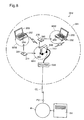
- the wireless network configuration system GH2 shown in Fig. 8 includes virtually all of the components of the wireless network configuration system GH1 of the first embodiment shown in Fig. 1.
- each of the components common to the two embodiments is indicated using the same numbers in the tens and ones places and/or the same letters used in Fig. 1, and will not be further described in this Specification.
- the wireless network configuration system GH2 of the second embodiment differs from the wireless network configuration system GH1 of the first embodiment in that configuration to form a wireless LAN between the access point 20 and the terminal 50 (60) and configuration for connection to the Internet IN are realized using RFID (Radio Frequency Identification), a specification governing wireless identification of individual devices or units and data transmission and receipt.
- RFID uses an RFID tag comprising a chip having a built-in IC and antenna and a reader/writer that transmits radio waves to the RFID tag and reads and writes information stored in the IC of the RFID tag.
- This system GH2 includes an encryption key setting system LH2 that, when a wireless LAN is to be formed, sets a common WEP key in the terminal 50 (60) and the access point 20 via wireless radio wave transmission of key data indicating the contents of the WEP key used as an encryption key within a small range that can be reached by the radio waves transmitted by the reader/writer (in the second embodiment, the secure communication area MR1 (MR2)). Because RFID transmits using electromagnetic induction, the effective range is normally only several centimeters.
- the wireless network configuration system GH2 includes an RFID card 270 (271) having an RFID tag 280 (281), an access point 220 having a reader/writer 282, and a terminal 250 (260) having a reader/writer 284.
- the RFID tag 280 (281) is a so-called passive tag that generates electric power using the induced electromotive force arising from the receipt of radio waves from the reader/writer 282 (284), and uses this electric power to activate the incorporated IC.
- Configuration information QJ comprising information needed to form a wireless LAN between the terminal 250 and the access point 220 and information needed to configure the connection to the Internet IN (such as data indicating the MAC address of the terminal 250, data regarding the WEP key that serves as an encryption key used when wireless communication takes place between the terminal 250 and the access point 220, and WAN connection configuration data) is stored in advance in the IC of the RFID tag 280, and similarly, configuration information QJ pertaining to the terminal 260 is stored in advance in the IC of the RFID 281.
- the effective range of the radio waves transmitted by the reader/writer 282 i.e., the secure communication area MR1
- the effective range of the radio waves transmitted by the reader/writer 284 i.e., the secure communication area MR2
- the effective range of the radio waves transmitted by the access point 20 of the first embodiment i.e., the wireless communication area AR1.
- the configuration information QJ stored in the IC of the RFID tag 280 (281) of the RFID card 270 (271) is read by the reader/writer 284 of the terminal 250 (260).
- the configuration information QJ stored in the IC of the RFID tag 280 (281) of the RFID card 270 (271) is read by the reader/writer 282 of the access point 220.
- the access point 220 and terminal 250 (260) respectively carry out MAC address registration, WEP key setting and configuration for connection to the Internet IN based on the read configuration information QJ.
- the owner of the terminal 250 (260) for which wireless LAN formation is sought can carry out the configuration tasks needed to form a wireless LAN and connect to the Internet IN by simply bringing the RFID card 270 (271) close to the access point 220 and the terminal 250 (260).
- the effective range of the radio waves emitted by the reader/writer 282 (284) is limited to the secure communication range MR1 (MR2), which is smaller than the wireless communication area AR1, there is a smaller risk that the radio waves that carry the configuration information QJ such as the WEP key data will be intercepted by an outside party. Therefore, the leakage of the configuration information QJ that includes the WEP key data can be made more unlikely to occur, and a wireless LAN with a high level of security can be realized.
- the access point 220 is located in a free spot in particular, the leakage of WEP key data to a third party during WEP key setting, for example, can be prevented for a large number of persons seeking to use the free spot. Therefore, the confidentiality of communications can be preserved for a large number of users.
- a construction may be adopted in which the reading of the RFID tag 280 (281) by the access point 220 is omitted.
- a large number of RFID cards 270, 271, ... that incorporate RFID tags 280, 281, ... that contain configuration information QJ that differs for each person's terminal are made available in advance.
- different WEP key data is recorded in the above RFID tags 280, 281, ... as the configuration information QJ (i.e., in which the RFID cards 270, 271, ... hold data for different WEP key values).
- all data pertaining to the WEP key data held by the RFID cards 270, 271, ... is recorded in the ROM 212 of the access point 220.
- the administrator of the free spot distributes the RFID cards 270, 271, ... individually to the users who wish to use a wireless LAN.
- the user brings his distributed RFID card close to his terminal 250 (260, ).
- the WEP key data recorded in the RFID tag of the RFID card is read by the reader/writer 284 of the terminal 250 (260, ).
- the CPU of the terminal 250 receives the WEP key data read by the reader/writer 284 and sets the value specified by this data as the WEP key to be used for communications with the access point 220.
- the CPU of the terminal 250 (260, %) then creates a WEP key packet in which the MAC address of the wireless LAN adapter 252 (262, %) is added as header information to the WEP key data read by the reader/writer 284, and this WEP key packet is sent wirelessly to the access point 200 from the wireless LAN adapter 252 (262, %) after being encoded using the previously-set WEP key.
- the access point 220 that receives the WEP key packet from the terminal 250 then extracts one item of data from all WEP key data stored in the ROM 212 and attempts to decode the WEP key packet using the value specified by the extracted WEP key data. If decoding fails, a different item of data is extracted from all WEP key data stored in the ROM 212, and WEP key packet decoding is attempted as before. These decoding attempts are continuously repeated until decoding is successful.
- the access point 220 When decoding is successful, the access point 220 identifies the value of the MAC address of the terminal 250 from the header information of the decoded WEP key packet, and registers the value of the successfully decoded WEP key, in association with the value of the corresponding MAC address, as the WEP key to be used for communications with the terminal 250. WEP keys for the other terminals 260, ... are registered via the identical processing as described above for the terminal 250.
- a common WEP key can be set for the terminal 250 (260, %) and the access point 220 without bringing the RFID card 270 (271, ...) close to the access point 220, thereby permitting more freedom in regard to the location at which the access point 220 is installed.
- a WEP key can be set easily even where the access point 220 is installed at a location that cannot be reached by the user.
- the RFID cards 270, 271, ... can be used only once, ensuring that the WEP key data assigned to each user is unique. Naturally, it is acceptable if the WEP key data recorded in the RFID tags 280, 281, ... of used RFID cards 270, 271, ... is rewritten with data indicating a value that has not yet been used by anyone, which would enable the used RFID cards 270, 271, ... to be reused.
- an RFID card 270 (271) was used as the medium on which to record the configuration information QJ, but the configuration tasks required for wireless LAN formation and for connection to the Internet IN can also be carried out easily and automatically without using this RFID card 270 (271).
- a construction may be envisioned in which an RFID tag in which the configuration information QJ is stored in advance is incorporated in the wireless LAN adapter 252 (262) in a form that may be read by the terminal 250 (260).
- the configuration information QJ stored in the RFID tag of the wireless LAN adapter 252 (262) is read by the reader/writer 282 of the access point 220 and the CPU of the terminal 250 (260). Based on the configuration information QJ read in this fashion, the access point 220 and the terminal 250 (260) each carry out MAC address registration, WEP key setting and configuration for connection to the Internet IN.
- the owner of a terminal 250 (260) who wishes to form a wireless LAN can carry out the configuration tasks needed to form a wireless LAN and connect to the Internet IN via the exceedingly simple method of bringing his terminal 250 (260) in which the wireless LAN adapter 252 (262) is installed close to the access point 220. Furthermore, where a wireless LAN is to be formed for a large number of terminal owners, it is not necessary to make a large number of RFID cards 270, 271 ... available or to include a reader/writer in the each of the terminals 250, 260, which makes the system construction simpler.
- RFID-based construction used passive-type RFIDs
- active-type tags that incorporate a power source and transmit radio waves to a reader/writer using the power from this power source may be used instead.
- the information needed for forming a wireless LAN between the terminal and the access point and the information needed for configuring the terminal's connection to the Internet IN was stored in recording media such as the ROM 12 of the access point 20, the CD-ROM 51, the ROM or hard disk of the terminal 50 (60), or an RFID tag, it is not essential that these recording media contain all information included in the configuration information QJ.
- recording media such as the ROM 12 of the access point 20, the CD-ROM 51, the ROM or hard disk of the terminal 50 (60), or an RFID tag
- it is acceptable if only the data regarding the computing equation K used to seek the value of the WEP key is stored
- it is acceptable if only the common WEP key data set in the terminal 250 (260) and the access point 220 is stored.
- an external antenna is connected to the access point 20 via hard-wiring, such that MAC address registration and WEP key setting are carried out via wireless communication between the external antenna and the terminal 50.
- This increases the degree of freedom in regard to the location at which the access point 20 can be installed. For example, by placing an external antenna in a corner of a store and using the area surrounding the external antenna as the WEP key setting area while installing the access point 20 in the center of the store, the size of the wireless communication area can be maximized within the store.
- the access point 20 may naturally be placed in a location other than a free spot (such as in a home or office).
- WEP was used as the technology by which to encode the contents of the data exchanged between the terminals and the access point, but an encoding technology other than WEP may be used.
- a public-key encryption method (a method in which different encryption keys are used for encoding the data and decoding the encoded data) may be used.
- WPA Wi-Fi Protected Access
- WEP Wi-Fi Protected Access
Landscapes
- Engineering & Computer Science (AREA)
- Computer Security & Cryptography (AREA)
- Computer Networks & Wireless Communication (AREA)
- Signal Processing (AREA)
- Computer Hardware Design (AREA)
- Computing Systems (AREA)
- General Engineering & Computer Science (AREA)
- Technology Law (AREA)
- Mobile Radio Communication Systems (AREA)
- Small-Scale Networks (AREA)
- Storage Device Security (AREA)
Applications Claiming Priority (2)
| Application Number | Priority Date | Filing Date | Title |
|---|---|---|---|
| JP2003378322 | 2003-11-07 | ||
| JP2003378322A JP4290529B2 (ja) | 2003-11-07 | 2003-11-07 | アクセスポイント、端末、暗号鍵設定システム、暗号鍵設定方法、および、プログラム |
Publications (3)
| Publication Number | Publication Date |
|---|---|
| EP1530322A2 true EP1530322A2 (de) | 2005-05-11 |
| EP1530322A3 EP1530322A3 (de) | 2005-07-06 |
| EP1530322B1 EP1530322B1 (de) | 2008-07-09 |
Family
ID=34431344
Family Applications (1)
| Application Number | Title | Priority Date | Filing Date |
|---|---|---|---|
| EP20040256869 Expired - Lifetime EP1530322B1 (de) | 2003-11-07 | 2004-11-05 | Konfiguration eines Verschlüsselungsschlüssels im WLAN Zugangspunkt und im Terminal |
Country Status (8)
| Country | Link |
|---|---|
| US (2) | US8205073B2 (de) |
| EP (1) | EP1530322B1 (de) |
| JP (1) | JP4290529B2 (de) |
| KR (1) | KR100703120B1 (de) |
| CN (1) | CN100468999C (de) |
| AT (1) | ATE400941T1 (de) |
| DE (1) | DE602004014879D1 (de) |
| TW (1) | TWI273792B (de) |
Cited By (15)
| Publication number | Priority date | Publication date | Assignee | Title |
|---|---|---|---|---|
| DE102005004382B3 (de) * | 2005-01-31 | 2006-06-14 | Siemens Ag | Verfahren zum automatischen Aufbau einer Datenverbindung mit einem elektrischen Gerät |
| EP1821492A1 (de) * | 2006-02-15 | 2007-08-22 | Samsung Electronics Co., Ltd. | Verfahren und Vorrichtung zum Ausführen einer Anwendung |
| EP1968241A1 (de) * | 2007-03-06 | 2008-09-10 | Koninklijke KPN N.V. | Verfahren zum Erhalt von Zugang auf ein Kommunikationsnetzwerk und Kommunikationssystem |
| CN100431308C (zh) * | 2006-01-27 | 2008-11-05 | 智易科技股份有限公司 | 无线局域网络系统及其设定方法 |
| EP2309805A1 (de) | 2009-10-11 | 2011-04-13 | Research In Motion Limited | Handhabung eines falschen WEP-Schlüssels und zugehöriger Batterieentleerungs- und Kommunikationsaustauschfehler |
| EP2352281A4 (de) * | 2009-10-26 | 2012-06-06 | Lg Electronics Inc | Steuerverfahren für ein innerhalb eines unabhängigen raums zwischen mehreren physisch getrennten unabhängigen räumen positioniertes digital-fernsehgerät (dtv) und entsprechendes digital-fernsehgerät |
| GB2486798A (en) * | 2010-12-22 | 2012-06-27 | British Telecomm | Automatic configuration of wireless access between a wireless device and an access point |
| US8272561B2 (en) | 2009-10-26 | 2012-09-25 | Lg Electronics Inc. | Digital broadcasting system and method of processing data in digital broadcasting system |
| EP2495957A4 (de) * | 2009-10-26 | 2013-05-29 | Lg Electronics Inc | Steuerverfahren für ein innerhalb eines unabhängigen raums zwischen mehreren physisch getrennten unabhängigen räumen positioniertes dtv (digital-fernsehgerät) und entsprechendes dtv |
| CN103369526A (zh) * | 2012-03-31 | 2013-10-23 | 华为终端有限公司 | 密钥信息处理方法及设备 |
| WO2014004723A1 (en) * | 2012-06-28 | 2014-01-03 | Qualcomm Incorporated | Method and apparatus for restricting access to a wireless system |
| DE102006010193B4 (de) * | 2005-03-11 | 2014-02-13 | Dell Products L.P. | Systeme und Verfahren zum Management von Out-of-Band Geräteverbindungen |
| US8695063B2 (en) | 2009-10-11 | 2014-04-08 | Blackberry Limited | Authentication failure in a wireless local area network |
| EP2495959A4 (de) * | 2009-10-26 | 2015-03-25 | Lg Electronics Inc | Steuerverfahren für ein innerhalb eines unabhängigen raums zwischen mehreren physisch getrennten unabhängigen räumen positioniertes dtv (digital-fernsehgerät) und entsprechendes dtv |
| EP2495960A4 (de) * | 2009-10-26 | 2015-04-01 | Lg Electronics Inc | Steuerverfahren für ein innerhalb eines unabhängigen raums zwischen mehreren physisch getrennten unabhängigen räumen positioniertes dtv (digital-fernsehgerät) und entsprechendes dtv |
Families Citing this family (82)
| Publication number | Priority date | Publication date | Assignee | Title |
|---|---|---|---|---|
| JP4543657B2 (ja) * | 2003-10-31 | 2010-09-15 | ソニー株式会社 | 情報処理装置および方法、並びにプログラム |
| US8316438B1 (en) | 2004-08-10 | 2012-11-20 | Pure Networks Llc | Network management providing network health information and lockdown security |
| US7925729B2 (en) | 2004-12-07 | 2011-04-12 | Cisco Technology, Inc. | Network management |
| US7987499B2 (en) * | 2004-08-18 | 2011-07-26 | Broadcom Corporation | Method and system for exchanging setup configuration protocol information in beacon frames in a WLAN |
| US7930737B2 (en) * | 2004-08-18 | 2011-04-19 | Broadcom Corporation | Method and system for improved communication network setup utilizing extended terminals |
| US7542572B2 (en) * | 2004-12-01 | 2009-06-02 | Cisco Technology, Inc. | Method for securely and automatically configuring access points |
| US8478849B2 (en) | 2004-12-07 | 2013-07-02 | Pure Networks LLC. | Network administration tool |
| US8085695B2 (en) * | 2005-01-25 | 2011-12-27 | Intel Corporation | Bootstrapping devices using automatic configuration services |
| US8200782B2 (en) * | 2005-04-29 | 2012-06-12 | Hewlett-Packard Development Company, L.P. | Communication with a mobile device |
| JP4774823B2 (ja) * | 2005-06-16 | 2011-09-14 | ソニー株式会社 | 無線通信システム、無線通信設定方法、無線通信装置、無線通信設定プログラム及び無線通信設定プログラム格納媒体 |
| JP2007013287A (ja) | 2005-06-28 | 2007-01-18 | Canon Inc | 撮像装置 |
| JP4628198B2 (ja) * | 2005-06-28 | 2011-02-09 | 株式会社バッファロー | セキュリティ設定処理システム |
| US7912017B2 (en) * | 2005-06-29 | 2011-03-22 | Sony Corporation | Wireless connection system and wireless connection method |
| US7702087B2 (en) * | 2005-09-02 | 2010-04-20 | Cisco Technology, Inc | Method and apparatus for activating and managing VoIP phone with RFID |
| US7570939B2 (en) * | 2005-09-06 | 2009-08-04 | Apple Inc. | RFID network arrangement |
| JP4419936B2 (ja) * | 2005-09-13 | 2010-02-24 | 船井電機株式会社 | クライアント・サーバシステム |
| DE102005045118B4 (de) * | 2005-09-21 | 2007-08-23 | Siemens Ag | Anmeldeverfahren zwischen Teilnehmern eines Kommunikationssystems und Teilnehmer |
| US20070116291A1 (en) * | 2005-11-09 | 2007-05-24 | Shmuel Silverman | System and method for utilizing a proximity network system for providing wireless communication network authentication |
| US8041035B2 (en) * | 2005-12-30 | 2011-10-18 | Intel Corporation | Automatic configuration of devices upon introduction into a networked environment |
| JP2007184858A (ja) * | 2006-01-10 | 2007-07-19 | Seiko Epson Corp | 画像表示システム |
| US9130993B2 (en) * | 2006-02-09 | 2015-09-08 | Sony Corporation | Wireless connection system and wireless connection method |
| JP4781125B2 (ja) * | 2006-02-17 | 2011-09-28 | キヤノン株式会社 | 情報処理システム、情報処理装置、及び周辺装置 |
| JP5061290B2 (ja) * | 2006-10-30 | 2012-10-31 | 株式会社メガチップス | 無線通信システム |
| US20080150698A1 (en) * | 2006-12-26 | 2008-06-26 | G2 Microsystems, Inc. | Radio frequency identification tag with passive and active features |
| US8325627B2 (en) * | 2007-04-13 | 2012-12-04 | Hart Communication Foundation | Adaptive scheduling in a wireless network |
| US20080273486A1 (en) * | 2007-04-13 | 2008-11-06 | Hart Communication Foundation | Wireless Protocol Adapter |
| US8356431B2 (en) * | 2007-04-13 | 2013-01-22 | Hart Communication Foundation | Scheduling communication frames in a wireless network |
| US8230108B2 (en) * | 2007-04-13 | 2012-07-24 | Hart Communication Foundation | Routing packets on a network using directed graphs |
| US8670746B2 (en) * | 2007-04-13 | 2014-03-11 | Hart Communication Foundation | Enhancing security in a wireless network |
| US8570922B2 (en) * | 2007-04-13 | 2013-10-29 | Hart Communication Foundation | Efficient addressing in wireless hart protocol |
| US7761613B2 (en) * | 2007-07-06 | 2010-07-20 | Belkin International, Inc. | Electrical device configuration system and method |
| US9491077B2 (en) | 2007-07-13 | 2016-11-08 | Cisco Technology, Inc. | Network metric reporting system |
| US9026639B2 (en) | 2007-07-13 | 2015-05-05 | Pure Networks Llc | Home network optimizing system |
| US8700743B2 (en) * | 2007-07-13 | 2014-04-15 | Pure Networks Llc | Network configuration device |
| US8391487B2 (en) | 2007-07-24 | 2013-03-05 | Cisco Technology, Inc. | Secure remote configuration of device capabilities |
| EP2192772B1 (de) * | 2007-08-24 | 2015-08-12 | Mitsubishi Electric Corporation | Vorrichtung mit begrenztem empfang |
| DE102007046668A1 (de) * | 2007-09-27 | 2009-04-09 | Siemens Ag | Verfahren zur Bereitstellung eines Zugriffs für einen Rechner auf ein über ein Kommunikationsnetz nutzbares Gerät |
| WO2009108373A2 (en) * | 2008-02-27 | 2009-09-03 | Fisher-Rosemount Systems, Inc. | Join key provisioning of wireless devices |
| JP5184922B2 (ja) * | 2008-03-07 | 2013-04-17 | 株式会社アイ・オー・データ機器 | ルータ装置 |
| GB0805803D0 (en) * | 2008-03-31 | 2008-04-30 | British Telecomm | Method of installing a wireless network |
| EP2294858A4 (de) * | 2008-06-23 | 2014-07-02 | Hart Comm Foundation | Analysegerät für ein drahtloses kommunikationsnetzwerk |
| US8744404B2 (en) * | 2008-08-28 | 2014-06-03 | Qualcomm Incorporated | Method and system for restricted access configuration of access point base stations |
| JP5229629B2 (ja) * | 2009-01-23 | 2013-07-03 | 株式会社リコー | 無線情報処理端末装置 |
| JP2010278781A (ja) * | 2009-05-28 | 2010-12-09 | Sharp Corp | 通信装置、中継装置、通信システム、通信装置の制御方法、プログラム、及び記録媒体 |
| JP4856743B2 (ja) * | 2009-08-06 | 2012-01-18 | 株式会社バッファロー | 無線通信装置、無線通信システム、および、ネットワーク装置 |
| JP2011081515A (ja) * | 2009-10-05 | 2011-04-21 | Nec Computertechno Ltd | コンピュータ装置、icタグ、該コンピュータ装置におけるブートドライブ設定方法、およびブートドライブ設定プログラム |
| US8250612B2 (en) * | 2009-10-26 | 2012-08-21 | Lg Electronics Inc. | Digital broadcasting system and method of processing data in digital broadcasting system |
| CN102771064B (zh) | 2010-02-26 | 2015-09-30 | Lg电子株式会社 | 电子设备及其操作方法 |
| CN102783196B (zh) * | 2010-03-01 | 2015-11-25 | Abb研究有限公司 | 两个临时连接的装置之间的无线通信 |
| JP5053400B2 (ja) | 2010-03-15 | 2012-10-17 | 株式会社バッファロー | 無線lan装置、プロトコル実行方法及びそのプログラム |
| US8724515B2 (en) | 2010-03-26 | 2014-05-13 | Cisco Technology, Inc. | Configuring a secure network |
| US8649297B2 (en) | 2010-03-26 | 2014-02-11 | Cisco Technology, Inc. | System and method for simplifying secure network setup |
| JP5244854B2 (ja) | 2010-05-14 | 2013-07-24 | 株式会社バッファロー | 無線通信装置 |
| US9002009B2 (en) * | 2010-06-15 | 2015-04-07 | Los Alamos National Security, Llc | Quantum key distribution using card, base station and trusted authority |
| US8745370B2 (en) * | 2010-06-28 | 2014-06-03 | Sap Ag | Secure sharing of data along supply chains |
| DE102010031931A1 (de) * | 2010-07-22 | 2012-01-26 | Siemens Aktiengesellschaft | Verfahren zum Registrieren einer drahtlosen Kommunikationseinrichtung an einer Basiseinrichtung sowie entsprechendes System |
| JP5269844B2 (ja) * | 2010-07-28 | 2013-08-21 | 株式会社バッファロー | 暗号鍵共有方法、無線端末、及びアクセスポイント |
| JP5277236B2 (ja) | 2010-11-26 | 2013-08-28 | 株式会社バッファロー | 可搬型ネットワーク接続装置 |
| WO2012155031A1 (en) * | 2011-05-11 | 2012-11-15 | Karrick Robert A | System for eliminating coins from cash transactions |
| JP5171989B2 (ja) * | 2011-05-12 | 2013-03-27 | キヤノン株式会社 | 撮像装置 |
| AU2011101297B4 (en) * | 2011-08-15 | 2012-06-14 | Uniloc Usa, Inc. | Remote recognition of an association between remote devices |
| US20130088335A1 (en) * | 2011-10-07 | 2013-04-11 | Symbol Technologies, Inc. | Mobile device staging with rfid tags |
| CN102594674B (zh) * | 2012-02-09 | 2014-10-08 | 烽火通信科技股份有限公司 | 实现双vlan交叉转发的方法及装置 |
| CN103298144A (zh) * | 2012-03-02 | 2013-09-11 | 中兴通讯股份有限公司 | 一种通过NFC进行Wi-Fi连接的方法、系统和终端 |
| US9420462B2 (en) | 2012-04-25 | 2016-08-16 | Panasonic Corporation | Wireless communication apparatus, communication device, wireless communication method, and wireless communication control program |
| JP2013247400A (ja) * | 2012-05-23 | 2013-12-09 | Nec Access Technica Ltd | 無線設定装置、無線設定方法、及び無線設定プログラム |
| JP5675747B2 (ja) | 2012-10-18 | 2015-02-25 | オリンパス株式会社 | 無線通信システム、携帯端末、デジタルカメラ、通信方法およびプログラム |
| US8874898B2 (en) * | 2012-12-14 | 2014-10-28 | Intel Corporation | Power line based theft protection of electronic devices |
| JP2016508749A (ja) * | 2012-12-14 | 2016-03-24 | リナック エー/エス | 電動アクチュエータシステム |
| KR102185365B1 (ko) * | 2013-07-31 | 2020-12-01 | 삼성전자주식회사 | 동일한 네트워크 상의 복수개의 ap 장치 중 하나의 ap 장치와 단말기를 연결하는 방법 및 장치 |
| JP6311246B2 (ja) | 2013-09-13 | 2018-04-18 | 沖電気工業株式会社 | 登録装置、通信装置及びネットワーク登録システム |
| WO2015126960A1 (en) * | 2014-02-18 | 2015-08-27 | Benu Networks, Inc. | Cloud controller for self-optimized networks |
| JP5815064B2 (ja) * | 2014-03-27 | 2015-11-17 | キヤノン株式会社 | 無線通信装置、x線センサ、及び無線通信システム |
| JP6368531B2 (ja) * | 2014-04-28 | 2018-08-01 | 達広 白井 | 暗号処理装置、暗号処理システム、および暗号処理方法 |
| KR102281019B1 (ko) | 2014-09-18 | 2021-07-26 | 삼성전자주식회사 | 전자 장치 및 전자 장치에서 데이터를 처리하는 방법 |
| JP6687824B2 (ja) * | 2014-11-10 | 2020-04-28 | 合同会社先端位置情報基盤研究所 | 小電力信号送信端末用ビーコン信号発生システム及び小電力信号送信端末 |
| CN105208559A (zh) * | 2015-08-18 | 2015-12-30 | 耿懿超 | 一种无线网络配置方法及其配置装置 |
| JP2015228711A (ja) * | 2015-09-24 | 2015-12-17 | キヤノン株式会社 | 無線通信装置、無線通信方法及びプログラム |
| JP6212146B2 (ja) * | 2016-02-23 | 2017-10-11 | 株式会社Subaru | 複合材賦形装置及び複合材賦形方法 |
| JP6558279B2 (ja) * | 2016-03-08 | 2019-08-14 | 富士通株式会社 | 情報処理システム、情報処理装置、情報処理方法、情報処理プログラム |
| US20170346688A1 (en) * | 2016-05-26 | 2017-11-30 | Pentair Water Pool And Spa, Inc. | Installation Devices for Connecting Pool or Spa Devices to a Local Area Network |
| CA3087480A1 (en) * | 2018-01-02 | 2019-07-11 | Laterpay Ag | Methods for access point systems and payment systems therefor |
Family Cites Families (8)
| Publication number | Priority date | Publication date | Assignee | Title |
|---|---|---|---|---|
| JP3945963B2 (ja) | 2000-05-09 | 2007-07-18 | 株式会社リコー | アクセスポイント装置 |
| JP3585422B2 (ja) | 2000-06-01 | 2004-11-04 | シャープ株式会社 | アクセスポイント装置及びその認証処理方法 |
| US8140845B2 (en) * | 2001-09-13 | 2012-03-20 | Alcatel Lucent | Scheme for authentication and dynamic key exchange |
| US8817757B2 (en) * | 2001-12-12 | 2014-08-26 | At&T Intellectual Property Ii, L.P. | Zero-configuration secure mobility networking technique with web-based authentication interface for large WLAN networks |
| US7451222B2 (en) * | 2002-02-13 | 2008-11-11 | Gateway Inc. | Client-centered WEP settings on a LAN |
| US7421266B1 (en) * | 2002-08-12 | 2008-09-02 | Mcafee, Inc. | Installation and configuration process for wireless network |
| KR20040090161A (ko) * | 2003-04-16 | 2004-10-22 | 엘지전자 주식회사 | 영상표시기기의 절전장치 및 방법 |
| JP2005092915A (ja) * | 2003-09-12 | 2005-04-07 | Toshiba Corp | 半導体集積回路装置およびその情報記憶方法 |
-
2003
- 2003-11-07 JP JP2003378322A patent/JP4290529B2/ja not_active Expired - Lifetime
-
2004
- 2004-11-05 EP EP20040256869 patent/EP1530322B1/de not_active Expired - Lifetime
- 2004-11-05 US US10/982,031 patent/US8205073B2/en active Active
- 2004-11-05 DE DE200460014879 patent/DE602004014879D1/de not_active Expired - Lifetime
- 2004-11-05 AT AT04256869T patent/ATE400941T1/de not_active IP Right Cessation
- 2004-11-05 TW TW93134045A patent/TWI273792B/zh not_active IP Right Cessation
- 2004-11-06 KR KR20040090161A patent/KR100703120B1/ko not_active Expired - Fee Related
- 2004-11-08 CN CNB2004100907570A patent/CN100468999C/zh not_active Expired - Lifetime
-
2011
- 2011-11-22 US US13/302,993 patent/US8561168B2/en not_active Expired - Fee Related
Cited By (22)
| Publication number | Priority date | Publication date | Assignee | Title |
|---|---|---|---|---|
| DE102005004382B3 (de) * | 2005-01-31 | 2006-06-14 | Siemens Ag | Verfahren zum automatischen Aufbau einer Datenverbindung mit einem elektrischen Gerät |
| DE102006010193B4 (de) * | 2005-03-11 | 2014-02-13 | Dell Products L.P. | Systeme und Verfahren zum Management von Out-of-Band Geräteverbindungen |
| CN100431308C (zh) * | 2006-01-27 | 2008-11-05 | 智易科技股份有限公司 | 无线局域网络系统及其设定方法 |
| EP1821492A1 (de) * | 2006-02-15 | 2007-08-22 | Samsung Electronics Co., Ltd. | Verfahren und Vorrichtung zum Ausführen einer Anwendung |
| US10582505B2 (en) | 2006-02-15 | 2020-03-03 | Samsung Electronics Co., Ltd. | Method and apparatus for executing an application automatically according to the approach of wireless device |
| US10492203B2 (en) | 2006-02-15 | 2019-11-26 | Samsung Electronics Co., Ltd. | Method and apparatus for executing an application automatically according to the approach of wireless device |
| US9118498B2 (en) | 2006-02-15 | 2015-08-25 | Samsung Electronics Co., Ltd. | Method and apparatus for executing an application automatically according to the approach of wireless device |
| EP1968241A1 (de) * | 2007-03-06 | 2008-09-10 | Koninklijke KPN N.V. | Verfahren zum Erhalt von Zugang auf ein Kommunikationsnetzwerk und Kommunikationssystem |
| EP2309805A1 (de) | 2009-10-11 | 2011-04-13 | Research In Motion Limited | Handhabung eines falschen WEP-Schlüssels und zugehöriger Batterieentleerungs- und Kommunikationsaustauschfehler |
| US8427991B2 (en) | 2009-10-11 | 2013-04-23 | Research In Motion Limited | Handling wrong WEP key and related battery drain and communication exchange failures |
| US9030985B2 (en) | 2009-10-11 | 2015-05-12 | Blackberry Limited | Handling mismatch of cryptographic keys and related battery drain and communication exchange failures |
| US8695063B2 (en) | 2009-10-11 | 2014-04-08 | Blackberry Limited | Authentication failure in a wireless local area network |
| EP2495960A4 (de) * | 2009-10-26 | 2015-04-01 | Lg Electronics Inc | Steuerverfahren für ein innerhalb eines unabhängigen raums zwischen mehreren physisch getrennten unabhängigen räumen positioniertes dtv (digital-fernsehgerät) und entsprechendes dtv |
| EP2495959A4 (de) * | 2009-10-26 | 2015-03-25 | Lg Electronics Inc | Steuerverfahren für ein innerhalb eines unabhängigen raums zwischen mehreren physisch getrennten unabhängigen räumen positioniertes dtv (digital-fernsehgerät) und entsprechendes dtv |
| EP2495957A4 (de) * | 2009-10-26 | 2013-05-29 | Lg Electronics Inc | Steuerverfahren für ein innerhalb eines unabhängigen raums zwischen mehreren physisch getrennten unabhängigen räumen positioniertes dtv (digital-fernsehgerät) und entsprechendes dtv |
| US8272561B2 (en) | 2009-10-26 | 2012-09-25 | Lg Electronics Inc. | Digital broadcasting system and method of processing data in digital broadcasting system |
| EP2352281A4 (de) * | 2009-10-26 | 2012-06-06 | Lg Electronics Inc | Steuerverfahren für ein innerhalb eines unabhängigen raums zwischen mehreren physisch getrennten unabhängigen räumen positioniertes digital-fernsehgerät (dtv) und entsprechendes digital-fernsehgerät |
| GB2486798B (en) * | 2010-12-22 | 2015-09-09 | British Telecomm | Wireless configuration |
| GB2486798A (en) * | 2010-12-22 | 2012-06-27 | British Telecomm | Automatic configuration of wireless access between a wireless device and an access point |
| CN103369526A (zh) * | 2012-03-31 | 2013-10-23 | 华为终端有限公司 | 密钥信息处理方法及设备 |
| WO2014004723A1 (en) * | 2012-06-28 | 2014-01-03 | Qualcomm Incorporated | Method and apparatus for restricting access to a wireless system |
| US9049593B2 (en) | 2012-06-28 | 2015-06-02 | Qualcomm Incorporated | Method and apparatus for restricting access to a wireless system |
Also Published As
| Publication number | Publication date |
|---|---|
| ATE400941T1 (de) | 2008-07-15 |
| US8561168B2 (en) | 2013-10-15 |
| CN100468999C (zh) | 2009-03-11 |
| JP4290529B2 (ja) | 2009-07-08 |
| CN1614921A (zh) | 2005-05-11 |
| KR100703120B1 (ko) | 2007-04-05 |
| TWI273792B (en) | 2007-02-11 |
| US20050160138A1 (en) | 2005-07-21 |
| HK1077950A1 (zh) | 2006-02-24 |
| DE602004014879D1 (de) | 2008-08-21 |
| KR20050044304A (ko) | 2005-05-12 |
| JP2005142907A (ja) | 2005-06-02 |
| EP1530322B1 (de) | 2008-07-09 |
| US20120093316A1 (en) | 2012-04-19 |
| TW200516898A (en) | 2005-05-16 |
| EP1530322A3 (de) | 2005-07-06 |
| US8205073B2 (en) | 2012-06-19 |
Similar Documents
| Publication | Publication Date | Title |
|---|---|---|
| EP1530322B1 (de) | Konfiguration eines Verschlüsselungsschlüssels im WLAN Zugangspunkt und im Terminal | |
| EP1145096B1 (de) | Mobiltelefon auto-pc-logon | |
| US20190394183A1 (en) | Communication system and method, information processing terminal and method, and information processing device and method | |
| JP4524306B2 (ja) | 許可方法 | |
| EP1733581B1 (de) | Teilnehmer-identitätsmodul | |
| JP4611504B2 (ja) | コンピュータ・アプリケーションへのアクセスを許可するための方法 | |
| EP2988534A2 (de) | Verfahren zur konfiguration der drahtlosen verbindung über nahfeldkommunikationsfunktion und bilderzeugungsvorrichtung zur durchführung des verfahrens | |
| US20040248514A1 (en) | Short distance wireless communication system utilizing portable terminals and wireless communication device for the system | |
| US20090144456A1 (en) | Interface Device for Securely Extending Computer Functionality | |
| US20060168647A1 (en) | Secure method and system for creating a plug and play network | |
| EP1629634B1 (de) | Sichere authentifizierung in einem drahtlosen hausnetzwerk | |
| JP2000003336A (ja) | 携帯型データ通信端末装置におけるユーザ認証方法及びユーザ認証システム | |
| JP4405309B2 (ja) | アクセスポイント、無線lan接続方法、無線lan接続プログラムを記録した媒体および無線lanシステム | |
| JP2010033193A (ja) | 認証システム及び認証用サーバ装置 | |
| US20150373757A1 (en) | Wireless connection system and wireless connection method | |
| US8032753B2 (en) | Server and system for transmitting certificate stored in fixed terminal to mobile terminal and method using the same | |
| CN104754568A (zh) | 基于nfc的身份识别方法及装置 | |
| US20050138303A1 (en) | Storage device | |
| KR101853970B1 (ko) | 인증번호 중계 방법 | |
| JP2003348660A (ja) | 無線通信システム、認証サーバ、端末装置および認証方法 | |
| JP2006005398A (ja) | アクセスポイント、無線lan接続方法、無線lan接続プログラムを記録した媒体および無線lanシステム | |
| JP2009124751A (ja) | アクセスポイント、端末、暗号鍵設定システム、暗号鍵設定方法、および、プログラム | |
| JP2004133747A (ja) | 認証システムおよび認証方法 | |
| HK1077950B (en) | Access point, terminal, encryption key configuration system, encryption key configuration method, and program | |
| JP2003150558A (ja) | ネットワーク・コンピュータ、認証情報管理システム、及びコンピュータ・ネットワーク運営システム |
Legal Events
| Date | Code | Title | Description |
|---|---|---|---|
| PUAI | Public reference made under article 153(3) epc to a published international application that has entered the european phase |
Free format text: ORIGINAL CODE: 0009012 |
|
| AK | Designated contracting states |
Kind code of ref document: A2 Designated state(s): AT BE BG CH CY CZ DE DK EE ES FI FR GB GR HU IE IS IT LI LU MC NL PL PT RO SE SI SK TR |
|
| AX | Request for extension of the european patent |
Extension state: AL HR LT LV MK YU |
|
| PUAL | Search report despatched |
Free format text: ORIGINAL CODE: 0009013 |
|
| AK | Designated contracting states |
Kind code of ref document: A3 Designated state(s): AT BE BG CH CY CZ DE DK EE ES FI FR GB GR HU IE IS IT LI LU MC NL PL PT RO SE SI SK TR |
|
| AX | Request for extension of the european patent |
Extension state: AL HR LT LV MK YU |
|
| 17P | Request for examination filed |
Effective date: 20051027 |
|
| AKX | Designation fees paid |
Designated state(s): AT BE BG CH CY CZ DE DK EE ES FI FR GB GR HU IE IS IT LI LU MC NL PL PT RO SE SI SK TR |
|
| 17Q | First examination report despatched |
Effective date: 20060201 |
|
| GRAP | Despatch of communication of intention to grant a patent |
Free format text: ORIGINAL CODE: EPIDOSNIGR1 |
|
| GRAS | Grant fee paid |
Free format text: ORIGINAL CODE: EPIDOSNIGR3 |
|
| GRAA | (expected) grant |
Free format text: ORIGINAL CODE: 0009210 |
|
| AK | Designated contracting states |
Kind code of ref document: B1 Designated state(s): AT BE BG CH CY CZ DE DK EE ES FI FR GB GR HU IE IS IT LI LU MC NL PL PT RO SE SI SK TR |
|
| REG | Reference to a national code |
Ref country code: GB Ref legal event code: FG4D |
|
| REG | Reference to a national code |
Ref country code: CH Ref legal event code: EP |
|
| REF | Corresponds to: |
Ref document number: 602004014879 Country of ref document: DE Date of ref document: 20080821 Kind code of ref document: P |
|
| REG | Reference to a national code |
Ref country code: IE Ref legal event code: FG4D |
|
| REG | Reference to a national code |
Ref country code: SE Ref legal event code: TRGR |
|
| PG25 | Lapsed in a contracting state [announced via postgrant information from national office to epo] |
Ref country code: ES Free format text: LAPSE BECAUSE OF FAILURE TO SUBMIT A TRANSLATION OF THE DESCRIPTION OR TO PAY THE FEE WITHIN THE PRESCRIBED TIME-LIMIT Effective date: 20081020 Ref country code: PT Free format text: LAPSE BECAUSE OF FAILURE TO SUBMIT A TRANSLATION OF THE DESCRIPTION OR TO PAY THE FEE WITHIN THE PRESCRIBED TIME-LIMIT Effective date: 20081209 Ref country code: IS Free format text: LAPSE BECAUSE OF FAILURE TO SUBMIT A TRANSLATION OF THE DESCRIPTION OR TO PAY THE FEE WITHIN THE PRESCRIBED TIME-LIMIT Effective date: 20081109 |
|
| PG25 | Lapsed in a contracting state [announced via postgrant information from national office to epo] |
Ref country code: BG Free format text: LAPSE BECAUSE OF FAILURE TO SUBMIT A TRANSLATION OF THE DESCRIPTION OR TO PAY THE FEE WITHIN THE PRESCRIBED TIME-LIMIT Effective date: 20081009 Ref country code: SI Free format text: LAPSE BECAUSE OF FAILURE TO SUBMIT A TRANSLATION OF THE DESCRIPTION OR TO PAY THE FEE WITHIN THE PRESCRIBED TIME-LIMIT Effective date: 20080709 Ref country code: AT Free format text: LAPSE BECAUSE OF FAILURE TO SUBMIT A TRANSLATION OF THE DESCRIPTION OR TO PAY THE FEE WITHIN THE PRESCRIBED TIME-LIMIT Effective date: 20080709 |
|
| PG25 | Lapsed in a contracting state [announced via postgrant information from national office to epo] |
Ref country code: BE Free format text: LAPSE BECAUSE OF FAILURE TO SUBMIT A TRANSLATION OF THE DESCRIPTION OR TO PAY THE FEE WITHIN THE PRESCRIBED TIME-LIMIT Effective date: 20080709 |
|
| PG25 | Lapsed in a contracting state [announced via postgrant information from national office to epo] |
Ref country code: EE Free format text: LAPSE BECAUSE OF FAILURE TO SUBMIT A TRANSLATION OF THE DESCRIPTION OR TO PAY THE FEE WITHIN THE PRESCRIBED TIME-LIMIT Effective date: 20080709 Ref country code: DK Free format text: LAPSE BECAUSE OF FAILURE TO SUBMIT A TRANSLATION OF THE DESCRIPTION OR TO PAY THE FEE WITHIN THE PRESCRIBED TIME-LIMIT Effective date: 20080709 |
|
| PLBE | No opposition filed within time limit |
Free format text: ORIGINAL CODE: 0009261 |
|
| STAA | Information on the status of an ep patent application or granted ep patent |
Free format text: STATUS: NO OPPOSITION FILED WITHIN TIME LIMIT |
|
| PG25 | Lapsed in a contracting state [announced via postgrant information from national office to epo] |
Ref country code: CZ Free format text: LAPSE BECAUSE OF FAILURE TO SUBMIT A TRANSLATION OF THE DESCRIPTION OR TO PAY THE FEE WITHIN THE PRESCRIBED TIME-LIMIT Effective date: 20080709 Ref country code: SK Free format text: LAPSE BECAUSE OF FAILURE TO SUBMIT A TRANSLATION OF THE DESCRIPTION OR TO PAY THE FEE WITHIN THE PRESCRIBED TIME-LIMIT Effective date: 20080709 Ref country code: RO Free format text: LAPSE BECAUSE OF FAILURE TO SUBMIT A TRANSLATION OF THE DESCRIPTION OR TO PAY THE FEE WITHIN THE PRESCRIBED TIME-LIMIT Effective date: 20080709 |
|
| 26N | No opposition filed |
Effective date: 20090414 |
|
| PG25 | Lapsed in a contracting state [announced via postgrant information from national office to epo] |
Ref country code: MC Free format text: LAPSE BECAUSE OF NON-PAYMENT OF DUE FEES Effective date: 20081130 |
|
| REG | Reference to a national code |
Ref country code: CH Ref legal event code: PL |
|
| PG25 | Lapsed in a contracting state [announced via postgrant information from national office to epo] |
Ref country code: IT Free format text: LAPSE BECAUSE OF FAILURE TO SUBMIT A TRANSLATION OF THE DESCRIPTION OR TO PAY THE FEE WITHIN THE PRESCRIBED TIME-LIMIT Effective date: 20080709 |
|
| PG25 | Lapsed in a contracting state [announced via postgrant information from national office to epo] |
Ref country code: CH Free format text: LAPSE BECAUSE OF NON-PAYMENT OF DUE FEES Effective date: 20081130 Ref country code: LI Free format text: LAPSE BECAUSE OF NON-PAYMENT OF DUE FEES Effective date: 20081130 |
|
| PG25 | Lapsed in a contracting state [announced via postgrant information from national office to epo] |
Ref country code: PL Free format text: LAPSE BECAUSE OF FAILURE TO SUBMIT A TRANSLATION OF THE DESCRIPTION OR TO PAY THE FEE WITHIN THE PRESCRIBED TIME-LIMIT Effective date: 20080709 |
|
| PG25 | Lapsed in a contracting state [announced via postgrant information from national office to epo] |
Ref country code: HU Free format text: LAPSE BECAUSE OF FAILURE TO SUBMIT A TRANSLATION OF THE DESCRIPTION OR TO PAY THE FEE WITHIN THE PRESCRIBED TIME-LIMIT Effective date: 20090110 Ref country code: CY Free format text: LAPSE BECAUSE OF FAILURE TO SUBMIT A TRANSLATION OF THE DESCRIPTION OR TO PAY THE FEE WITHIN THE PRESCRIBED TIME-LIMIT Effective date: 20080709 Ref country code: LU Free format text: LAPSE BECAUSE OF NON-PAYMENT OF DUE FEES Effective date: 20081105 |
|
| PG25 | Lapsed in a contracting state [announced via postgrant information from national office to epo] |
Ref country code: TR Free format text: LAPSE BECAUSE OF FAILURE TO SUBMIT A TRANSLATION OF THE DESCRIPTION OR TO PAY THE FEE WITHIN THE PRESCRIBED TIME-LIMIT Effective date: 20080709 |
|
| PG25 | Lapsed in a contracting state [announced via postgrant information from national office to epo] |
Ref country code: GR Free format text: LAPSE BECAUSE OF FAILURE TO SUBMIT A TRANSLATION OF THE DESCRIPTION OR TO PAY THE FEE WITHIN THE PRESCRIBED TIME-LIMIT Effective date: 20081010 |
|
| PGFP | Annual fee paid to national office [announced via postgrant information from national office to epo] |
Ref country code: FI Payment date: 20121112 Year of fee payment: 9 Ref country code: IE Payment date: 20121119 Year of fee payment: 9 Ref country code: FR Payment date: 20121130 Year of fee payment: 9 |
|
| PGFP | Annual fee paid to national office [announced via postgrant information from national office to epo] |
Ref country code: SE Payment date: 20121113 Year of fee payment: 9 |
|
| REG | Reference to a national code |
Ref country code: SE Ref legal event code: EUG |
|
| REG | Reference to a national code |
Ref country code: FR Ref legal event code: ST Effective date: 20140731 |
|
| REG | Reference to a national code |
Ref country code: IE Ref legal event code: MM4A |
|
| PG25 | Lapsed in a contracting state [announced via postgrant information from national office to epo] |
Ref country code: FI Free format text: LAPSE BECAUSE OF NON-PAYMENT OF DUE FEES Effective date: 20131105 Ref country code: SE Free format text: LAPSE BECAUSE OF NON-PAYMENT OF DUE FEES Effective date: 20131106 |
|
| PG25 | Lapsed in a contracting state [announced via postgrant information from national office to epo] |
Ref country code: IE Free format text: LAPSE BECAUSE OF NON-PAYMENT OF DUE FEES Effective date: 20131105 |
|
| PG25 | Lapsed in a contracting state [announced via postgrant information from national office to epo] |
Ref country code: FR Free format text: LAPSE BECAUSE OF NON-PAYMENT OF DUE FEES Effective date: 20131202 |
|
| PGFP | Annual fee paid to national office [announced via postgrant information from national office to epo] |
Ref country code: NL Payment date: 20191014 Year of fee payment: 16 |
|
| PGFP | Annual fee paid to national office [announced via postgrant information from national office to epo] |
Ref country code: GB Payment date: 20191031 Year of fee payment: 16 |
|
| REG | Reference to a national code |
Ref country code: DE Ref legal event code: R082 Ref document number: 602004014879 Country of ref document: DE Representative=s name: DEHNS GERMANY PARTNERSCHAFT MBB, DE Ref country code: DE Ref legal event code: R082 Ref document number: 602004014879 Country of ref document: DE Representative=s name: DEHNSGERMANY PARTNERSCHAFT VON PATENTANWAELTEN, DE |
|
| REG | Reference to a national code |
Ref country code: NL Ref legal event code: MM Effective date: 20201201 |
|
| GBPC | Gb: european patent ceased through non-payment of renewal fee |
Effective date: 20201105 |
|
| PG25 | Lapsed in a contracting state [announced via postgrant information from national office to epo] |
Ref country code: NL Free format text: LAPSE BECAUSE OF NON-PAYMENT OF DUE FEES Effective date: 20201201 |
|
| PG25 | Lapsed in a contracting state [announced via postgrant information from national office to epo] |
Ref country code: GB Free format text: LAPSE BECAUSE OF NON-PAYMENT OF DUE FEES Effective date: 20201105 |
|
| PGFP | Annual fee paid to national office [announced via postgrant information from national office to epo] |
Ref country code: DE Payment date: 20230929 Year of fee payment: 20 |
|
| REG | Reference to a national code |
Ref country code: DE Ref legal event code: R071 Ref document number: 602004014879 Country of ref document: DE |