EP1530321B1 - System und Verfahren zum Setzen der kryptographischen Schlüssel - Google Patents
System und Verfahren zum Setzen der kryptographischen Schlüssel Download PDFInfo
- Publication number
- EP1530321B1 EP1530321B1 EP04256868A EP04256868A EP1530321B1 EP 1530321 B1 EP1530321 B1 EP 1530321B1 EP 04256868 A EP04256868 A EP 04256868A EP 04256868 A EP04256868 A EP 04256868A EP 1530321 B1 EP1530321 B1 EP 1530321B1
- Authority
- EP
- European Patent Office
- Prior art keywords
- access point
- terminal
- encryption key
- communication range
- wireless communication
- Prior art date
- Legal status (The legal status is an assumption and is not a legal conclusion. Google has not performed a legal analysis and makes no representation as to the accuracy of the status listed.)
- Expired - Lifetime
Links
Images


Classifications
-
- H—ELECTRICITY
- H04—ELECTRIC COMMUNICATION TECHNIQUE
- H04W—WIRELESS COMMUNICATION NETWORKS
- H04W12/00—Security arrangements; Authentication; Protecting privacy or anonymity
- H04W12/02—Protecting privacy or anonymity, e.g. protecting personally identifiable information [PII]
-
- H—ELECTRICITY
- H04—ELECTRIC COMMUNICATION TECHNIQUE
- H04L—TRANSMISSION OF DIGITAL INFORMATION, e.g. TELEGRAPHIC COMMUNICATION
- H04L63/00—Network architectures or network communication protocols for network security
- H04L63/04—Network architectures or network communication protocols for network security for providing a confidential data exchange among entities communicating through data packet networks
- H04L63/0428—Network architectures or network communication protocols for network security for providing a confidential data exchange among entities communicating through data packet networks wherein the data content is protected, e.g. by encrypting or encapsulating the payload
- H04L63/0492—Network architectures or network communication protocols for network security for providing a confidential data exchange among entities communicating through data packet networks wherein the data content is protected, e.g. by encrypting or encapsulating the payload by using a location-limited connection, e.g. near-field communication or limited proximity of entities
-
- H—ELECTRICITY
- H04—ELECTRIC COMMUNICATION TECHNIQUE
- H04L—TRANSMISSION OF DIGITAL INFORMATION, e.g. TELEGRAPHIC COMMUNICATION
- H04L63/00—Network architectures or network communication protocols for network security
- H04L63/06—Network architectures or network communication protocols for network security for supporting key management in a packet data network
- H04L63/061—Network architectures or network communication protocols for network security for supporting key management in a packet data network for key exchange, e.g. in peer-to-peer networks
-
- H—ELECTRICITY
- H04—ELECTRIC COMMUNICATION TECHNIQUE
- H04L—TRANSMISSION OF DIGITAL INFORMATION, e.g. TELEGRAPHIC COMMUNICATION
- H04L9/00—Cryptographic mechanisms or cryptographic arrangements for secret or secure communications; Network security protocols
- H04L9/32—Cryptographic mechanisms or cryptographic arrangements for secret or secure communications; Network security protocols including means for verifying the identity or authority of a user of the system or for message authentication, e.g. authorization, entity authentication, data integrity or data verification, non-repudiation, key authentication or verification of credentials
-
- H—ELECTRICITY
- H04—ELECTRIC COMMUNICATION TECHNIQUE
- H04W—WIRELESS COMMUNICATION NETWORKS
- H04W12/00—Security arrangements; Authentication; Protecting privacy or anonymity
- H04W12/03—Protecting confidentiality, e.g. by encryption
- H04W12/033—Protecting confidentiality, e.g. by encryption of the user plane, e.g. user's traffic
-
- H—ELECTRICITY
- H04—ELECTRIC COMMUNICATION TECHNIQUE
- H04W—WIRELESS COMMUNICATION NETWORKS
- H04W12/00—Security arrangements; Authentication; Protecting privacy or anonymity
- H04W12/04—Key management, e.g. using generic bootstrapping architecture [GBA]
-
- H—ELECTRICITY
- H04—ELECTRIC COMMUNICATION TECHNIQUE
- H04W—WIRELESS COMMUNICATION NETWORKS
- H04W84/00—Network topologies
- H04W84/02—Hierarchically pre-organised networks, e.g. paging networks, cellular networks, WLAN [Wireless Local Area Network] or WLL [Wireless Local Loop]
- H04W84/10—Small scale networks; Flat hierarchical networks
- H04W84/12—WLAN [Wireless Local Area Networks]
Definitions
- the present invention relates to a technique of setting an encryption key, which is used to encrypt radio communication data transmitted between an access point as a relay station for a wireless LAN and a terminal equipped with a device for connecting with the wireless LAN prior to the transmission, in the terminal and in the access point.
- Access points as radio relay stations for a wireless LAN are used as the device of connecting multiple computers at separate locations to the Internet not only in the places where specific people continuously act, such as homes and offices (hereafter referred to as private spaces), but in the places where general public temporarily act, such as hotels, airports, shopping malls, parks, and stations (hereafter referred to as public spaces).
- US 2003/0092395 discloses a system having a PC as a base station to which devices, such as print servers, are wirelessly connected.
- Another proposed technique connects an access point located in a public space with a broadband line, which ensures high-speed Internet access service, such as an xDSL line or a CATV line, and gives a space for Internet access (hereafter referred to as a free spot) to the general public in the coverage of radio wave transmitted from the access point (radio communication area).
- the administrator of the public space is authorized to use a certain broadband line.
- the broadband line is open to terminals possessed by the respective users of the public space via the access point for the wireless LAN. This enhances the convenience of the user's Internet access and increases the utilization rate of the public space.
- the free space may give only limited people (for example, clients) the authorization for access to the Internet via the wireless LAN in the radio communication area. In such cases, it is required to prevent illegal access of any unauthorized person to the network.
- a number of people use the same free spot, and the radio waves for wireless communication are frequently transmitted between terminals possessed by the respective people and the access point. For sufficient protection of privacy of each person, it is essential to effectively prevent the contents of communication from being leaked to any third person by interception of the radio waves in the radio communication area.
- One proposed technique utilizes a MAC (Media Access Control) address, which is an intrinsic identification number allocated to a device for connecting the wireless LAN (for example, a wireless LAN adapter) attached to the terminal, and registers the allocated MAC address in the access point.
- the access point authenticates the MAC address in response to an access from the terminal, and rejects the request of access to the network from the terminal when the input MAC address is not identical with the registered MAC address.
- This technique is referred to as the MAC address restriction technique (for example, see Japanese Patent Laid-Open Gazette No. 2001-320373 ).
- WEP Wired Equivalent Privacy
- each user who wants to utilize the free spot is required to register the MAC address and set the WEP key with regard to the terminal of the user, prior to use of the free spot.
- the prior art security technique requires manual registration of the MAC address in the access point and manual setting of the WEP key in the terminal, and is rather troublesome and inconvenient in the case of new enrollment of a terminal for the wireless LAN.
- a free spot installed in a public space, there are a large number of users who want to utilize the free spot, and the number is increasing. It is extremely inconvenient and unpractical to ask each of the many users who possess own terminals to operate the terminal for registration of the MAC address and setting of the WEP key as the conditions of utilizing the free spot.
- the WEP key of an arbitrary letter string set in the terminal should also be set in the access point. It is preferable to utilize the wireless LAN for the setting.
- the WEP key data carried on the radio wave is transmitted from the terminal to the access point by wireless.
- the access point receives the transmitted WEP key and sets the WEP key mapped to the terminal.
- the user of the terminal is then allowed to enjoy various services (for example, Internet access service) via the wireless LAN immediately after transmission of the WEP key.
- various services for example, Internet access service
- the third person who illegally obtains the leaked WEP key can analyze and grasp all the data transmitted between the access point and the terminal with the WEP key. This disables the security system based on encryption. Especially in the access point of the free spot, the WEP key is set in the terminals of many users who want to utilize the free spot. It is thus highly demanded to effectively prevent leakage of the WEP key and ensure sufficient secrecy of communication for a large number of users.
- Document US 2003 092 395 discloses an encryption key setting system to be used to encrypt data transmitted between an access point and a terminal.
- the access point restricts a radio communication range to be narrower (short distance) than a general range to perform the transmission of the setting parameters. This arrangement prevents leakage of the setting parameters.
- the goal of the present invention is to solve the problems noted above, and to realize with a simple method the new addition of a terminal using a wireless LAN while preventing leaking of data that represents an encryption, key.
- an encryption key setting system as claimed in claim 1.
- the system performs encryption with an encryption key in advance of communication of wireless communication data through wireless communication using electric waves.
- the aforementioned wireless LAN connection device is a device that is mounted on the terminal.
- Examples of this wireless LAN connection device could include a wireless LAN adapter or wireless LAN card.
- the encryption key setting system of the present invention setting of the encryption key that is used when encrypting wireless communication data communicated between an access point and a terminal is started by operating the operating unit that is provided on a device for which remote operation is possible in relation to said access point.
- This kind of encryption key setting is performed by wireless communication of encryption key data that represents the contents of the encryption key between said terminal and said access point when the wireless communication range between the access point and the terminal is made narrower than the normal communication range.
- a variety of embodiments can be considered as embodiments for realizing a communication range restriction module. For example, it is also possible to realize this on the access point side. If realized using the access point, when there is an instruction to start encryption key setting, the wireless communication range is narrowed and the encryption key is set under the conditions decided based on this instruction. Therefore, it is not necessary to always have the access point in a state of receiving encryption key settings.
- the aforementioned instruction module there are items like ones that perform instructions by operation of a device for which remote operation is possible by wireless communication of electric waves to the access point such as with a terminal equipped with a wireless LAN connection device or a remote controller.
- Control can be performed to make the wireless communication range narrower than the normal communication range when the access point receives instructions to the effect of setting an encryption key from said terminal, and control can be performed to return the wireless communication range to the normal communication range when the encryption key setting by said wireless setting module is completed. By doing this, it becomes possible for the owner of the terminal to make encryption key settings without touching the access point. It is also possible to have the communication range restriction module be a module that restricts said wireless communication range by adjusting the transmission output of said access point.
- the communication range restriction module be a shielding body that shields the terminal and access point for which said encryption key setting is performed in relation to said wireless signal.
- the access point can also be equipped with a registration module that registers information that is inherent to the terminal that is subject to communication.
- a registration module that registers information that is inherent to the terminal that is subject to communication.
- an encryption key setting method as claimed in claim 10.
- an authentication code setting system that is a system that sets the authentication code, which is required when a terminal which is equipped with a device for wireless LAN connection accesses specific data on a network by wireless communication using electric waves at an access point that is a relay for a wireless LAN, in at least one or the other of said terminals or said access point.
- the authentication code setting system comprises:
- possibilities include the individual information required for obtaining pay information from an access point (e.g. name of the terminal owner, or password, etc.), etc.
- the authentication code setting system sets the authentication code, which is required when a terminal accesses specific data on a network by wireless communication at an access point, in at least one or the other of said terminal or said access point.
- This kind of authentication code setting is started by operating an operating unit provided in a device that is capable of remote operation in relation to said access point, and when the wireless communication range between the access point and terminal is narrower than the normal communication range, this is performed by wireless communication of data that represents the contents of the authentication code (hereafter called authentication code data) between said terminal and said access point.
- Fig. 1 is an explanatory diagram that shows the structure of hardware that realizes encryption key setting system LH1 which is a first working example of the present invention
- Fig. 2 is an explanatory diagram that shows the structure of access point 20.
- Encryption key setting system LH1 is a system that, by performing wireless communication between terminal 50 and access point 20 within wireless communication area AR1 of a wireless LAN with key data that represents the contents of the WEP key as the encryption key traveling on an electric wave, sets the WEP key that access point 20 uses for terminal 50.
- access point (wireless base station) 20 which is a relay for a wireless LAN is installed in wireless communication area AR1.
- access point 20 comprises various parts such as CPU 11, ROM 12, RAM 13, non-volatile memory device such as a hard disk 14, WAN port 17 as a network interface, LAN port 22 as a connection to a wired LAN, radio communication interface 18, display controller 15, and input/output controller 16, etc. which are mutually connected by a bus to this CPU 11.
- the ROM 12 stores diverse programs relating to communication with terminals 50, 60, and 70 in the radio communication area AR1 and connection to the Internet IN, as well as data required for execution of these programs.
- a push-type registration button 127 is linked with the input-output controller 16.
- the registration button 127 has a pressing element exposed to the surface of the casing of the access point 20.
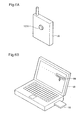
- the display controller 15 is linked with various display lamps 19 to show the connection status and the communication status of the wireless LAN by lighting or flashing on and off. Also, with this working example, a remote controller 30 with a registration button 127A like that shown in Fig. 6A is prepared.
- a dedicated remote controller 30 Even if a dedicated remote controller 30 is not provided, it is possible to realize this with a registration button TB realized by a program in terminal 50 that is equipped with a wireless LAN connection device 52 as shown in Fig. 6B .
- the structure is such that issuing of specific data from these devices is performed when a touch operation of the button or key equipped on said device (e.g. pressing operation of registration button 127A shown in Fig. 6A ) or a selection operation of a selection choice on a screen equipped on said device (e.g. clicking of the registration tab TB displayed on the screen in terminal 50 shown in Fig. 6B ), etc. is performed.
- a transmitter 25 for transmitting radio waves and a receiver 26 for receiving radio waves are connected with the radio communication interface 18.
- the transmitter 25 and the receiver 26 are built in the access point 20 in a radio-wave transmittable state to the outside and in a radio-wave receivable state from the outside, respectively.
- the radio communication area AR1 represents the coverage of the radio wave transmitted from the transmitter 25 and of the radio wave transmitted from the terminal 50, 60, and 70 and received by the receiver 26, in the case where standard values are set to the output of the transmitter 25 and to the reception sensitivity of the receiver 26.
- Setting the access point 20 constructs a wireless LAN having the radio communication area AR1 as the general communication range.
- An output changing program and a reception sensitivity changing program have been stored in advance as programs relating to communication with the terminal 50, 60, and 70 in the ROM 12.
- the output changing program describes a series of processing to temporarily change the standard setting value of the output of the transmitter 25.
- the reception sensitivity changing program describes a series of processing to temporarily change the standard setting value of the reception sensitivity of the receiver 26.
- the setting value is changed by an operation of multiplying the current standard setting value by 1/n (where n is a preset constant).
- the CPU 11 executes the output changing program and the reception sensitivity changing program and transfers the changed values of the output and the reception sensitivity to the transmitter 25 and the receiver 26 via the radio communication interface 18. This process accordingly changes the output of radio wave transmitted from the transmitter 25 and the reception density of radio wave in the receiver 26.
- Each of the terminals 50, 60, and 70 is a known book-type personal computer and has a control unit including a CPU, a ROM, and a RAM and a storage unit, such as a hard disk and a CD-ROM drive. This is, however, not restrictive at all, and a personal digital assistant, a portable terminal, or any other equivalent device is applicable for each of the terminals 50, 60, and 70.
- Wireless LAN adapters 52, 62, and 72 are respectively attached to the terminals 50, 60, and 70 as the device for connecting with the wireless LAN to allow transmission of radio wave to and from the access point 20.
- a device driver of each wireless LAN adapter 52, 62, or 72 is incorporated in the corresponding terminal 50, 60, or 70, so that the terminal 50, 60 or 70 can recognize the wireless LAN adapter 52, 62, or 72 attached thereto and control the attached wireless LAN adapter 52, 62, or 72.
- a MAC address as an intrinsic identification number is allocated to each of the wireless LAN adapters 52, 62, and 72.
- the terminal 50, 60, or 70 which is a computer entering the radio communication area AR1, establishes wireless communication with the access point 20 via transmission of radio waves between the wireless LAN adapter 52, 62, or 72 attached to the terminal 50, 60, or 70 and the access point 20.
- the access point 20 and the wireless LAN adapter 52, 62, or 72 are capable of converting the data to be transmitted to a format suitable for communication, that is, packets. This theoretically allows for offline (in the state of no connection with the Internet) data transmission between the terminal 50, 60, or 70 and the access point 20.
- a router 28 with a built-in modem is linked with the WAN port 17 of the access point 20 via a cable.
- the router 28 identifies and discriminates each of the multiple terminals 50, 60, and 70 included in the wireless LAN from the other terminals, based on the MAC addresses respectively allocated to the wireless LAN adapters 52, 62, and 72.
- the built-in modem of the router 28 is connected to the Internet IN via a broadband communication line CL, such as a CATV line or an xDSL line, and an exclusive line of a provider PV.
- CL broadband communication line
- the router 28 accordingly functions as a gateway to connect the wireless LAN with the Internet IN.
- the access point 20 allows a terminal having the MAC address registered in the access point 20 (hereafter referred to as registered terminal) to gain access to the wireless LAN, among the terminals with wireless LAN adapters possessed by the users in the radio communication area AR1.
- the user of the registered terminal connects the terminal to the Internet IN via the access point 20 to fetch diverse pieces of information, such as Web contents, stored in a server SV on the Internet IN.
- the access point 20, does not allow any terminal having the MAC address unregistered in the access point 20 (hereafter referred to as unregistered terminal) to gain access to the wireless LAN, even when the terminal enters the radio communication area AR1.
- the radio communication area AR1 functions as a free spot that provides only the users of the registered terminals with the access service to the Internet IN.
- the terminals 50 and 60 are registered terminals, whereas the terminal 70 is an unregistered terminal.
- Data representing the details of various contracts, services, and the like are carried on the radio wave and are transmitted between the registered terminal and the access point 20.
- a transmitter device of transmitting the detailed data (either the registered terminal or the access point 20) encrypts the detailed data with an encryption key or a WEP key discussed previously, prior to the transmission, and transmits the encrypted detailed data (hereafter referred to as encrypted data) to a receiver device (either the access point 20 or the registered terminal).
- the receiver device decrypts the received encrypted data with the WEP key, so as to obtain the detailed data.
- the WEP represents a secret key encryption method (this method uses an identical encryption key for encrypting data and for decrypting the encrypted data) in conformity with the IEEE 802.11 standard.
- the encryption key may be a 64-bit WEP key or a 128-bit WEP key.
- the following describes a technique of setting the WEP key in the terminals 50 and 60.
- a program of registering the MAC addresses of the wireless LAN adapters 52 and 62 has been stored in advance as a program relating to communication with the terminals 50 and 60 in the ROM 12 of the access point 20.
- a utility program of the wireless LAN installed in each of the terminals 50 and 60 includes a program of setting the WEP key (WEP key setting program)
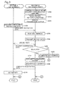
- the CPU of the terminal 50 or 60 executes the WEP key setting program, while the CPU 11 of the access point 20 executes the MAC registration program and the output changing program, so as to implement a security data setting process shown in the flowchart of Fig. 3 .
- the security data setting process registers the MAC addresses of the wireless LAN adapters 52 and 62 in the access point 20 and sets a common WEP key in the access point 20 and the terminal 50 or 60.
- Fig. 3 is a flowchart showing a security data setting routine.
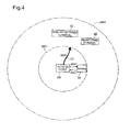
- Fig. 4 shows a radio wave transmittable range of the transmitter 25 after a change in output, as a security communication area MR1.
- the terminal 50 is the object of registration of the MAC address and the object of setting of the WEP key.
- the security data setting routine includes a routine A executed by the CPU of the terminal 50 and a routine B executed by the CPU 11 of the access point 20.
- the administrator of the access point 20 confirms that the terminal 50 is located within the security communication area MR1 (step S200) and operates the registration button 127 (step S210).
- the security communication area MR1 represents a transmittable range of the radio wave from the transmitter 25, when the standard setting value is temporarily lowered by execution of the output changing program discussed previously (see Fig. 4 ).
- the access point 20 executes the output changing program and lowers the output of the transmitter 25 to 1/n of the standard setting value (step S220).
- This process restricts the radio wave transmittable range of the transmitter 25 to the security communication area MR1 shown in Fig. 4 , which is narrower than the radio communication area AR1.
- the registered terminal that enters the radio communication area AR1 but is not located within the security communication area MR1 is thus not allowed to gain access to the access point 20.
- the terminal 50 specifies the MAC address of the wireless LAN adapter 52 and transmits a packet, which includes data representing an instruction of new enrollment for the wireless LAN (hereafter referred to as enrollment instruction) and the MAC address attached to the data as header information, to the access point 20 (step S100).
- the access point 20 reads the MAC address from the header information of the received packet and temporarily stores the MAC address into a buffer area of the RAM 13 (step S230).
- the access point 20 subsequently transmits data representing a selected WEP key for use (hereafter referred to as WEP key data) to the terminal 50 (step S250), and determines whether or not the WEP key data has been delivered to the terminal 50 successively (step S255).
- the decision of successful delivery is carried out by utilizing a data return function of the wireless LAN adapter 52.
- the access point 20 eliminates the MAC address stored in the RAM 13 (step S260) and exits from the routine B.
- the access point 20 executes the output changing program and restores the output of the transmitter 25 to the standard setting value (step S270). This process restores the radio wave transmittable range of the transmitter 25 to the general range (the radio communication area AR1). The registered terminal entering the radio communication area AR1 is thus allowed to gain access to the access point 20.
- the access point 20 then registers the MAC address of the terminal 50 into a management region of the storage device 14 (step S280). This completes registration of the MAC address of the terminal 50 in the access point 20.
- the terminal 50 receives the WEP key data delivered at step S250 and automatically sets the WEP key mapped to the IP address of the access point 20 (step S110). The terminal 50 then exits from the routine A. This completes setting of the WEP key mapped to the access point 20 in the terminal 50. After the registration of the MAC address and the setting of the WEP key, the detailed data are encrypted with the preset WEP key and the encrypted data are transmitted between the terminal 50 and the access point 20.
- the WEP key is automatically set in terminal 50.
- this kind of “automatic setting of the WEP key by wireless communication” is performed, it becomes possible to easily realize new addition of a terminal 50 that uses the wireless LAN, and to provide a wireless LAN that is easy to subscribe to.
- the owner of terminal 50 and the administrator of access point 20 do not have to connect terminal 50 and access point 20 using a cable, etc., and do not have to perform a manual task of creating or setting the WEP key.
- a free spot wireless LAN can have many people subscribe one after another who wish to use this LAN, because it is possible to greatly reduce the work required for making settings for each person.
- access point 20 when placing the WEP key data on electric waves and sending it to terminal 50, access point 20 changes the range for which electric waves sent from access point 20 reach from wireless communication area AR1 which is a normal range to a security communication area MR1 which is a narrower range. Because of this, there is a lower possibility of electric waves on which WEP key data is placed being intercepted. For example, in Fig. 4 , when WEP key data is transmitted from access point 20 to terminal 50, electric waves on which WEP key data is placed only reach within security communication area MR1 which is a narrower range (see arrow Q1), and they are not received at registered terminal 60 or non-registered terminal 70 which are outside security communication area MR1.
- access point 20 restricts the communication range temporarily according to receipt of data that represents subscriber instructions from terminal 50 and creates a WEP key, and after the created WEP key is transmitted to terminal 50, returns the communication range to its original state. Therefore, the owner of terminal 50 can perform WEP key setting without touching access point 20, which is easy and hygienic.
- access point 20 registers the terminal side MAC address together with the WEP key setting, and allows connection to the wireless LAN only for registered terminals 50 and 60. By doing this, it is possible to prevent connection to a wireless LAN by an unregistered terminal 70 by using a simple method. It is also possible to prevent in advance the infiltration by unregistered terminal 70 to registered terminals 50 and 60 and access point 20 on the LAN and therefore acquisition of various types of data such as the WEP key data.
- possibilities include (a) while registration button 127A is being pressed, (b) from when registration button 127A is pressed until the MAC address and WEP key are registered, and (c) from when registration button 127A is pressed until it is pressed again, etc.
- the terminal owner and access point administrator can perform WEP setting without touching the access point side registration point 127, etc., and to increase the degree of freedom of the access point installation position. For example, even when the access point is installed in a location that is difficult to reach by hand (e.g. the ceiling of a store), it is possible to smoothly perform setting of the WEP key with the terminal by using remote controller 30 or terminal 50.
- a location that is difficult to reach by hand e.g. the ceiling of a store
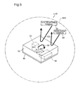
- Fig. 6 is an explanatory diagram that shows the structure of a device that realizes encryption key setting system LH2 which is a second working example of the present invention.
- Access point 20 and terminals 50, 60, and 70 have approximately the same structure as the first working example, and the same wireless communication area AR1 is formed as that of the first working example by this access point 20.
- access point 20 and terminal 50 are placed on sole plate 96.
- a shielding box 95 which has an empty part that can be subsumed is made to cover access point 20 and terminal 50.
- Shielding box 95 and sole plate 96 are formed using a metal such as iron, etc.
- setting of the WEP key is performed using the following procedure.
- the person wishing to subscribe to the wireless LAN goes to the location at which access point 20 is installed, and places terminal 50 which he owns and access point 20 on sole plate 96. At this time, it is also permissible to have access point 20 placed on sole plate 96 ahead of time.
- the person who wishes to subscribe to the wireless LAN operates terminal 50 and gives instructions to the effect to subscribe to the wireless LAN, and after that covers shielding box 95 on sole plate 96.
- Access point 20 receives data that represents subscribing instructions from terminal 50, and after a specified time from said receiving has elapsed (the time required to cover shielding box 95, for example), the same MAC address registration process and WEP key setting process as that of the first working example (the processes of step S100, step S230, step S260, step S280, and step S110) are performed. By doing this, the registration of the MAC address relating to terminal 50 is completed on the access point 20 side, the WEP key data created by access point 20 is transmitted to terminal 50, and WEP key setting to terminal 50 is completed.
- an external antenna is connected by wire to access point 20, and to perform MAC address registration and WEP key setting by wireless communication between the external antenna and terminal 50.
- WEP was used as the technology for encrypting the contents of data exchanged between terminals and an access point, but it is also permissible to use another encryption technology other than WEP.
- an encryption technology that is a publicly announced key encryption method (a method that uses different encryption keys for data encryption and decryption of encrypted data) can also be used.
- WPA Wi-Fi Protected Access
- WEP key setting was realized sending and receiving of electric waves between wireless LAN adapter 52 mounted on terminal 50 and the transmitter 25 and receiver 26 of access point 20, but it is also permissible to use a structure that performs EP key setting using communication that uses other wireless than this kind of electric wave.
- this other kind of wireless possibilities include infrared rays, light, voice signals, ultrasonic waves, and weak electric signals, etc.
- the infrared ray receiver on the access point 20 side is formed from a photo diode that has sensitivity to the infrared ray area, and the infrared ray transmitter on the terminal 50 side is formed by an LED that outputs light of infrared ray area wavelengths.
- the infrared ray transmission interface on the terminal 50 side converts the command signal from the CPU to a transmission wave for which this command signal is overlapped. The converted transmission wave is dispatched from the infrared ray dispatcher.
- transmission waves dispatched from terminal 50 in this way are received by the infrared ray receiver on the access point 20 side.
- the infrared ray receiver interface that accepts transmission waves received in this way converts the transmission waves to binarized command signals, and sends the command signals after conversion to CPU 11.
- the terminal 50 side MAC address is confirmed by checking two systems of information, electric waves and infrared rays. Therefore, it is possible to do a stricter check of terminals to allow to connect to the wireless LAN, and to completely prevent connection to the wireless LAN by unregistered terminals.
- infrared rays or light infrared rays and light have directivity, so the range for which it is possible for transmission waves to reach the access point is more limited than electric waves. Therefore, it is possible to prevent a third party from illicitly using another person's MAC address to register his own terminal using said MAC address to access point 20.
- the aforementioned infrared ray transmission interface and infrared ray receiver can also be realized by incorporating these in advance into terminal 50, and can also be realized by connecting the infrared ray dispatcher to the voice output terminal of terminal 50.
- the wireless communication range during setting of the WEP key was limited, but this kind of wireless communication range limitation can be applied not only to the WEP key but also to other information that is set by exchange between access point 20 and terminal 50.
- information for authenticating that the owner of the accessed terminal is the specified person (e.g. the terminal owner name, ID, or password, etc.) is registered in advance with access point 20 or terminal 50.
- the specified person e.g. the terminal owner name, ID, or password, etc.
Landscapes
- Engineering & Computer Science (AREA)
- Computer Security & Cryptography (AREA)
- Computer Networks & Wireless Communication (AREA)
- Signal Processing (AREA)
- Computer Hardware Design (AREA)
- Computing Systems (AREA)
- General Engineering & Computer Science (AREA)
- Mobile Radio Communication Systems (AREA)
- Small-Scale Networks (AREA)
- Circuits Of Receivers In General (AREA)
Claims (11)
- Verschlüsselungskey bzw. -schlüssel-Setzsystem (LH1, LH2), das eine Verschlüsselung mit einem Verschlüsselungskey vor einer Übertragung von Drahtloskommunikationsdaten über Drahtloskommunikation unter Verwendung elektrischer Wellen durchführt, wobei das Verschlüsselungskey-Setzsystem aufweist:einen Accesspoint bzw. Zugangspunkt (20), der einen Übergabepunkt bzw. ein Relay für ein Drahtlos-LAN darstellt; undein Terminal (50, 60, 70), das mit einer Vorrichtung (52, 62, 72) zur Drahtlos-LAN-Verbindung ausgestattet ist, und das einen Registrierknopf (TB) zum entfernten Bedienen des Accespoints (20) aufweist, und durch Bedienen des Registrierknopfs (TB) Anweisungen zum Beginn des Setzens des Verschlüsselungskeys an bzw. bei dem Accesspoint (20) gibt;wobei der Accesspoint (20) ein Kommunikationsbereichsbeschränkungsmodul aufweist, das auf Grundlage der Anweisungen den Drahtloskommunikationsbereich zwischen dem Accesspoint (20) und dem Terminal (50, 60, 70) so beschränkt, dass dieser enger bzw. schmaler als ein normaler Kommunikationsbereich ist, und ferner aufweist:ein Verschlüsselungskey-Setzmodul, das, wenn der Drahtloskommunikationsbereich durch das Kommunikationsbereichsbeschränkungsmodul beschränkt ist, den Verschlüsselungskey durch ein Durchführen einer Drahtloskommunikation bzw. -übertragung von Verschlüsselungskeydaten, die den Inhalt des Verschlüsselungskeys repräsentieren, zwischen Terminals (50, 60, 70), die in dem Kommunikationsbereich und dem Accesspoint (20) existieren, setzt, wobei ferner das Verschlüsselungskey-Setzmodul den Verschlüsselungskey setzt durch:Übertragen von einen ausgewählten WEP-Key repräsentierenden Daten zur Verwendung an das Terminal (50, 60, 70); undBestimmen, ob die WEP-Keydaten erfolgreich an das Terminal (50, 60, 70) geliefert wurden oder nicht, wobei das Bestimmen einer erfolgreichen Lieferung das Verwenden einer Datenrückkehr bzw. Rücksendefunktion des Terminals (50, 60, 70) umfasst; und dadurch gekennzeichnet, dass:der Accesspoint (20) eine dem Terminal (50, 60, 70) zugeordnete MAC-Adresse, welche in dem Accesspoint (20) gespeichert ist, als Antwort auf eine fehlgeschlagene Lieferung der WEP-Keydaten an das Terminal (50, 60, 70) eliminiert; unddie Verschlüsselungskeydaten durch den Accesspoint erzeugt werden.
- Verschlüsselungskey-Setzsystem (LH1, LH2) nach Anspruch 1, das ferner aufweist:ein Zustandsentscheidungsmodul, das Zustände bzw. über Zustände entscheidet, das den Drahtloskommunikationsbereich beschränkt, so dass dieser enger als der normale Kommunikationsbereich ist,wobei das Kommunikationsbereichsbeschränkungsmodul den Drahtloskommunikationsbereich beschränkt, während die durch das Zustandsentscheidungsmodul entschiedenen Zustände bestimmt werden.
- Verschlüsselungskey-Setzsystem (LH1, LH2) nach Anspruch 1 oder 2, wobei das Kommunikationsbereichsbeschränkungsmodul aufweist:erste Mittel, die eine Steuerung bzw. Kontrolle zur Beschränkung des Drahtloskommunikationsbereichs durchführen, so dass dieser enger ist als der normale Kommunikationsbereich, wenn der Accesspoint (20) Anweisungen zum Ziel eines Setzens eines Verschlüsselungskeys von dem Terminal (50) empfängt; undzweite Mittel, die eine Steuerung zum Rücksetzen des Drahtloskommunikationsbereichs auf den normalen Kommunikationsbereich durchführen, wenn das Verschlüsselungskeysetzen durch das Verschlüsselungskey-Setzmodul fertiggestellt ist.
- Verschlüsselungskey-Setzsystem (LH1, LH2) nach Anspruch 1, wobei das Kommunikationsbereichsbeschränkungsmodul den Drahtloskommunikationsbereich durch Einstellen der Transmissions- bzw. übertragungsausgabe des Accesspoints (20) beschränkt.
- Verschlüsselungskey-Setzsystem (LH1, LH2) nach Anspruch 1, wobei das Kommunikationsbereichsbeschränkungsmodul einen Abschirmkörper (95) aufweist, der das Terminal (50, 60, 70) und den Accesspoint (20), für welchen das Verschlüsselungskeysetzen ausgeführt wird, in Bezug auf das Drahtlossignal abschirmt.
- Verschlüsselungskey-Setzsystem (LH1, LH2) nach Anspruch 1, wobei der Accesspoint (20) mit einem Registriermodul versehen ist, das Information registriert, die dem Terminal (50, 60, 70) inhärent ist, welches einer Kommunikation unterworfen ist.
- Verschlüsselungskey-Setzsystem (LH1, LH2) nach Anspruch 1, wobei das Verschlüsselungskey-Setzmodul aufweist:ein Inhärentinformations-Empfangsmodul, das die dem Terminal (50, 60, 70) inhärente Information über die Drahtloskommunikation vor der Drahtlosübertragung der Verschlüsselungskeydaten durch elektrische Wellen empfängt; undein Terminalidentifikationsmodul, das das Terminal (50, 60, 70) zur Übertragung des Verschlüsselungskeys auf Grundlage der empfangenen inhärenten Information identifiziert.
- Verschlüsselungskey-Setzsystem (LH1, LH2) nach Anspruch 7, das ferner aufweist:ein Drahtloskommunikationsmodul, über bzw. durch welches der Accesspoint (20) und das Terminal (50, 60, 70) die dem Terminal inhärente Information über ein Medium, das keine elektrischen Wellen darstellt, austauschen, im Gegensatz zur Drahtloskommunikation, die die elektrischen Wellen verwendet,wobei das Terminalidentifikationsmodul das Terminal (50, 60, 70) zum Übertragen des Verschlüsselungskeys identifiziert, wenn die unter Verwendung einer Drahtloskommunikation durch die elektrischen Wellen empfangene inhärente Information der durch das Drahtloskommunikationsmodul empfangenen inhärenten Information entspricht.
- Verschlüsselungskey-Setzsystem (LH1, LH2) nach einem der vorstehenden Ansprüche, bei dem als Antwort auf eine erfolgreiche Lieferung der WEP-Keydaten an das Terminal (50, 60, 70) das Kommunikationsbereichsbeschränkungsmodul des Accesspoints (20) den Drahtloskommunikationsbereich auf den normalen Kommunikationsbereich wiederherstellt.
- Verschlüsselungskey-Setzverfahren, das einen Verschlüsselungskey, welcher während einer Verschlüsselung verwendet wird, an Terminals (50, 60, 70) setzt, vor einer Übertragung von Drahtloskommunikationsdaten durch Drahtloskommunikation unter Verwendung von elektrischen Wellen zwischen einem Accesspoint (20), der einen Übergabepunkt bzw. ein Relay für ein drahtloses LAN darstellt, und den Terminals (50, 60, 70), die mit Vorrichtungen (52, 62, 72) zur Drahtlos-LAN-Verbindung versehen sind, wobei das Verfahren beinhaltet:Empfangen von Anweisungen zum Beginn eines Drahtlos-Registrierprozesses von einer Vorrichtung entfernt von dem Accesspoint, welche dazu in der Lage ist, eine Drahtlos-Fernbedienung in Bezug auf den Accesspoint durchzuführen, wobei die Vorrichtung ein Terminal (50, 60, 70), und das Terminal einen Registrierknopf (TB) aufweist;dass der Accesspoint (20) den Drahtloskommunikationsbereich zwischen dem Accesspoint (20) und den Terminals (50, 60, 70) so beschränkt, dass dieser enger bzw. schmaler ist als ein normaler Kommunikationsbereich, wenn die Registrierverarbeitungs-Startanweisungen nach der Bedienung des Registrierknopfs (TB) empfangen werden;dass der Accesspoint (20) den Verschlüsselungskey setzt, indem er eine Drahtloskommunikation bzw. -übertragung der Verschlüsselungskeydaten, die den Inhalt des Verschlüsselungskeys repräsentieren, zwischen Terminals (50, 60, 70), die in dem Kommunikationsbereich existieren, wenn der Drahtloskommunikationsbereich beschränkt wurde, und dem Accesspoint (20) ausführt, und durch:Übertragen von einen ausgewählten WEP-Key repräsentierenden Daten zur Verwendung an das Terminal (50, 60, 70); undBestimmen, ob die WEP-Keydaten an das Terminal erfolgreich geliefert wurden oder nicht, wobei das Bestimmen einer erfolgreichen Lieferung das Verwenden einer Datenrückkehr- bzw. Rücksendefunktion des Terminals (50, 60, 70) beinhaltet; und dadurch gekennzeichnet, dass:als Antwort auf eine fehlgeschlagenen Lieferung der WEP-keydaten an das Terminal (50, 60, 70) der Accesspoint (20) eine dem Terminal (50, 60, 70) zugeordnete MAC-Adresse, die in dem Accesspoint (20) gespeichert ist, eliminiert; und dadurch, dass die Verschlüsselungskeydaten durch den Accesspoint erzeugt werden.
- Verschlüsselungskey-Setzverfahren nach Anspruch 10, bei dem als Antwort auf eine erfolgreiche Lieferung der WEP-Keydaten an das Terminal (50, 60, 70) der Accesspoint (20) den Drahtloskommunikationsbereich auf den normalen Kommunikationsbereich wiederherstellt.
Applications Claiming Priority (2)
| Application Number | Priority Date | Filing Date | Title |
|---|---|---|---|
| JP2003377072A JP4346413B2 (ja) | 2002-12-19 | 2003-11-06 | 暗号鍵設定システム、アクセスポイント、および、暗号鍵設定方法 |
| JP2003377072 | 2003-11-06 |
Publications (2)
| Publication Number | Publication Date |
|---|---|
| EP1530321A1 EP1530321A1 (de) | 2005-05-11 |
| EP1530321B1 true EP1530321B1 (de) | 2010-02-10 |
Family
ID=34431313
Family Applications (1)
| Application Number | Title | Priority Date | Filing Date |
|---|---|---|---|
| EP04256868A Expired - Lifetime EP1530321B1 (de) | 2003-11-06 | 2004-11-05 | System und Verfahren zum Setzen der kryptographischen Schlüssel |
Country Status (7)
| Country | Link |
|---|---|
| US (1) | US7522729B2 (de) |
| EP (1) | EP1530321B1 (de) |
| KR (1) | KR100679212B1 (de) |
| CN (1) | CN1614920A (de) |
| AT (1) | ATE457571T1 (de) |
| DE (1) | DE602004025436D1 (de) |
| TW (1) | TWI262011B (de) |
Families Citing this family (53)
| Publication number | Priority date | Publication date | Assignee | Title |
|---|---|---|---|---|
| US7879111B2 (en) * | 2006-11-02 | 2011-02-01 | Sony Corporation | System and method for RFID transfer of MAC, keys |
| JP3791489B2 (ja) * | 2002-12-13 | 2006-06-28 | ソニー株式会社 | ポータブルサーバ |
| KR100555381B1 (ko) * | 2002-12-19 | 2006-02-24 | 멜코 인코포레이티드 | 암호키 설정시스템 및 암호키 설정방법 |
| JP4724405B2 (ja) * | 2004-10-28 | 2011-07-13 | キヤノン株式会社 | 無線通信装置及び電子機器、並びにそれらの制御方法及びコンピュータプログラム |
| JP5032127B2 (ja) * | 2004-12-20 | 2012-09-26 | パナソニック株式会社 | 無線通信装置、通信制御方法 |
| US7577458B2 (en) * | 2005-01-30 | 2009-08-18 | Cisco Technology, Inc. | LCD display on wireless router |
| JP4455418B2 (ja) * | 2005-06-13 | 2010-04-21 | キヤノン株式会社 | 通信パラメータ設定方法及び通信装置 |
| JP4628198B2 (ja) * | 2005-06-28 | 2011-02-09 | 株式会社バッファロー | セキュリティ設定処理システム |
| DE102005045118B4 (de) * | 2005-09-21 | 2007-08-23 | Siemens Ag | Anmeldeverfahren zwischen Teilnehmern eines Kommunikationssystems und Teilnehmer |
| KR100800733B1 (ko) * | 2006-02-08 | 2008-02-01 | 삼성전자주식회사 | 블루투스 시스템 및 블루투스 본딩 프로세스 방법 |
| US20070199077A1 (en) * | 2006-02-22 | 2007-08-23 | Czuchry Andrew J | Secure communication system |
| JP4840970B2 (ja) * | 2006-02-23 | 2011-12-21 | キヤノン株式会社 | 通信装置と通信装置の制御方法及びプログラム |
| JP4946121B2 (ja) * | 2006-03-24 | 2012-06-06 | パナソニック株式会社 | 認証中継装置、認証中継システム、及び認証中継方法 |
| GB2436668B (en) * | 2006-03-28 | 2011-03-16 | Identum Ltd | Electronic data communication system |
| DE602006016773D1 (de) * | 2006-07-07 | 2010-10-21 | Research In Motion Ltd | Erzeugung von Sicheheitzugangsparametern für WLAN mobile Kommunikationsgeräte |
| US7831236B2 (en) * | 2006-07-07 | 2010-11-09 | Research In Motion Limited | Secure provisioning methods and apparatus for mobile communication devices operating in wireless local area networks (WLANS) |
| JP4850610B2 (ja) | 2006-07-31 | 2012-01-11 | キヤノン株式会社 | 通信装置及びその制御方法 |
| US20080046561A1 (en) * | 2006-08-17 | 2008-02-21 | Belkin International, Inc. | Networking hardware element to couple computer network elements and method of displaying information thereon |
| US7675862B2 (en) | 2006-08-17 | 2010-03-09 | Belkin International, Inc. | Networking hardware element to couple computer network elements and method of displaying a network layout map thereon |
| US20080040955A1 (en) * | 2006-08-21 | 2008-02-21 | Belkin Corporation | Instruction-wielding apparatus and method of presenting instructions thereon |
| US7844253B2 (en) * | 2006-10-19 | 2010-11-30 | Future Dial Inc. | Method and apparatus for using an electromagnetically shielded enclosure for exchanging secure data |
| JP4886463B2 (ja) | 2006-10-20 | 2012-02-29 | キヤノン株式会社 | 通信パラメータ設定方法、通信装置及び通信パラメータを管理する管理装置 |
| US20080095086A1 (en) * | 2006-10-23 | 2008-04-24 | Janne Linkola | Method of deploying an access point for an ip-based wireless network |
| CA2620673C (en) | 2006-10-23 | 2014-01-14 | T-Mobile Usa, Inc. | System and method for managing access point functionality and configuration |
| JP4983208B2 (ja) * | 2006-11-07 | 2012-07-25 | 富士通株式会社 | 中継局、無線通信方法 |
| KR100799794B1 (ko) * | 2007-01-16 | 2008-01-31 | 엘지전자 주식회사 | 네트워크 설정 기능을 가지는 리모트 컨트롤러 및 이를이용한 무선 네트워크 설정 방법 |
| CN101083556B (zh) * | 2007-07-02 | 2010-04-14 | 蔡水平 | 一种按地域分层次无线信息发布搜索交流应用系统 |
| JP5144162B2 (ja) * | 2007-08-01 | 2013-02-13 | キヤノン株式会社 | 通信装置及び通信パラメータを取得するための制御方法 |
| US8208635B2 (en) * | 2007-11-13 | 2012-06-26 | Rosemount Inc. | Wireless mesh network with secure automatic key loads to wireless devices |
| US7974236B2 (en) * | 2007-11-16 | 2011-07-05 | Ricoh Company, Ltd. | Approach for configuring Wi-Fi devices |
| JP4613969B2 (ja) | 2008-03-03 | 2011-01-19 | ソニー株式会社 | 通信装置、及び通信方法 |
| EP2266292A1 (de) * | 2008-04-22 | 2010-12-29 | Gigaset Communications GmbH | Verfahren zur zugriffskontrolle für einen konfigurierungs-zugang eines gerätes und gerät mit einer zugriffskontrolle für einen konfigurierungs-zugang |
| JP4894826B2 (ja) * | 2008-07-14 | 2012-03-14 | ソニー株式会社 | 通信装置、通信システム、報知方法、及びプログラム |
| US8619545B2 (en) | 2008-07-17 | 2013-12-31 | T-Mobile Usa, Inc. | System and method for selectively provisioning telecommunications services between an access point and a telecommunications network based on landline telephone detection |
| US8885635B2 (en) | 2008-07-17 | 2014-11-11 | T-Mobile Usa, Inc. | System and method for selectively provisioning telecommunications services between an access point and a telecommunications network using a subscriber identifier |
| KR101405914B1 (ko) | 2008-07-23 | 2014-06-12 | 삼성전자주식회사 | 디바이스를 ap에 등록하는 방법 및 그 장치 |
| JP2010068021A (ja) * | 2008-09-08 | 2010-03-25 | Olympus Corp | 通信端末および通信システム |
| US8320344B2 (en) | 2009-02-27 | 2012-11-27 | T-Mobile Usa, Inc. | System and method for provisioning telecommunications services between an access point and a telecommunications network and providing a missing information notification |
| US8484457B2 (en) | 2009-03-10 | 2013-07-09 | T-Mobile Usa, Inc. | Method of securely pairing devices with an access point for an IP-based wireless network |
| EP2426968A4 (de) * | 2009-04-30 | 2017-04-12 | Nec Corporation | Kommunikationsvorrichtung, verbindungsverfahren und verbindungsprogramm |
| US8881305B2 (en) | 2009-07-13 | 2014-11-04 | Blackberry Limited | Methods and apparatus for maintaining secure connections in a wireless communication network |
| US8838022B2 (en) * | 2010-04-13 | 2014-09-16 | Radeum, Inc. | System and method for securely pairing a wireless device using wireless communication |
| TWM405520U (en) * | 2010-10-29 | 2011-06-11 | Digi Triumph Technology Inc | Uninterrupted power detection system(I) |
| JP5987552B2 (ja) * | 2012-08-21 | 2016-09-07 | 株式会社リコー | 無線通信装置、プログラムおよび方法 |
| WO2014085124A1 (en) * | 2012-11-27 | 2014-06-05 | Motorola Solutions, Inc. | Systems and methods for visible light communications personal area network and wireless local area network interworking |
| US9525486B2 (en) | 2012-11-27 | 2016-12-20 | Extreme Networks, Inc. | Visible light communications personal area network controller and access point systems and methods |
| KR101510249B1 (ko) | 2013-10-15 | 2015-04-09 | 순천향대학교 산학협력단 | N스크린 환경에서의 안전한 디바이스 인증 방법 |
| CN104735727B (zh) * | 2013-12-24 | 2019-02-22 | 中国移动通信集团辽宁有限公司 | 一种基于信号检测的无线局域网分流方法及装置 |
| JP6283914B2 (ja) | 2014-06-13 | 2018-02-28 | パナソニックIpマネジメント株式会社 | 通信システム及び制御装置 |
| CN105635095A (zh) * | 2015-06-25 | 2016-06-01 | 宇龙计算机通信科技(深圳)有限公司 | 通信方法与接入点设备、通信方法与终端以及通信系统 |
| US10021731B2 (en) * | 2016-03-24 | 2018-07-10 | Panasonic Intellectual Property Management Co., Ltd. | Home interior monitoring system and communication control method |
| JP7300845B2 (ja) * | 2019-02-15 | 2023-06-30 | 三菱重工業株式会社 | 制御装置、産業用制御システムおよび暗号鍵寿命延長方法 |
| CN112286147B (zh) * | 2020-09-17 | 2021-08-20 | 华为技术有限公司 | 一种家居设备的控制方法及设备 |
Family Cites Families (8)
| Publication number | Priority date | Publication date | Assignee | Title |
|---|---|---|---|---|
| US6148205A (en) | 1998-06-30 | 2000-11-14 | Motorola, Inc. | Method and apparatus for secure registration within an in-home wireless network |
| JP3945963B2 (ja) | 2000-05-09 | 2007-07-18 | 株式会社リコー | アクセスポイント装置 |
| JP3585422B2 (ja) | 2000-06-01 | 2004-11-04 | シャープ株式会社 | アクセスポイント装置及びその認証処理方法 |
| JP3628250B2 (ja) | 2000-11-17 | 2005-03-09 | 株式会社東芝 | 無線通信システムで用いられる登録・認証方法 |
| EP1364494B1 (de) | 2001-01-30 | 2009-12-02 | Broadcom Corporation | Verfahren zum hinzufügen eines neuen Gerätes zu einem drahtlosen Netz |
| JP3915481B2 (ja) | 2001-11-14 | 2007-05-16 | セイコーエプソン株式会社 | 無線通信装置 |
| KR100888471B1 (ko) * | 2002-07-05 | 2009-03-12 | 삼성전자주식회사 | 링크 접속권한을 등급화 한 암호화 키 차등분배방법 및이를 이용한 로밍방법 |
| KR100555381B1 (ko) * | 2002-12-19 | 2006-02-24 | 멜코 인코포레이티드 | 암호키 설정시스템 및 암호키 설정방법 |
-
2004
- 2004-11-04 TW TW093133687A patent/TWI262011B/zh not_active IP Right Cessation
- 2004-11-04 US US10/983,263 patent/US7522729B2/en active Active
- 2004-11-04 CN CNA200410088906XA patent/CN1614920A/zh active Pending
- 2004-11-05 EP EP04256868A patent/EP1530321B1/de not_active Expired - Lifetime
- 2004-11-05 KR KR1020040089861A patent/KR100679212B1/ko not_active Expired - Fee Related
- 2004-11-05 DE DE602004025436T patent/DE602004025436D1/de not_active Expired - Lifetime
- 2004-11-05 AT AT04256868T patent/ATE457571T1/de not_active IP Right Cessation
Also Published As
| Publication number | Publication date |
|---|---|
| KR20050043709A (ko) | 2005-05-11 |
| EP1530321A1 (de) | 2005-05-11 |
| DE602004025436D1 (de) | 2010-03-25 |
| TW200525980A (en) | 2005-08-01 |
| US7522729B2 (en) | 2009-04-21 |
| US20050201557A1 (en) | 2005-09-15 |
| TWI262011B (en) | 2006-09-11 |
| CN1614920A (zh) | 2005-05-11 |
| ATE457571T1 (de) | 2010-02-15 |
| KR100679212B1 (ko) | 2007-02-07 |
Similar Documents
| Publication | Publication Date | Title |
|---|---|---|
| EP1530321B1 (de) | System und Verfahren zum Setzen der kryptographischen Schlüssel | |
| US7289631B2 (en) | Encryption key setting system, access point, encryption key setting method, and authentication code setting system | |
| JP4346413B2 (ja) | 暗号鍵設定システム、アクセスポイント、および、暗号鍵設定方法 | |
| JP5244843B2 (ja) | 単一の加入者識別モジュールを使用する無線リンクによる複数の装置の同時認証 | |
| CN100417274C (zh) | 用于松散耦合互操作的基于证书的认证授权计费方案 | |
| EP1538776B1 (de) | Vorrichtung zur Verarbeitung von kryptographischen Schlüsseln, Zugangspunkt, Endgerät für drahtloses Lokales Netzwerk, und Verfahren zur Verarbeitung von kryptographischen Schlüsseln | |
| US20050238172A1 (en) | Cipher key setting system, access point, and cipher key setting method | |
| JP2005531203A6 (ja) | 単一の加入者識別モジュールを使用する無線リンクによる複数の装置の同時認証 | |
| JP4405309B2 (ja) | アクセスポイント、無線lan接続方法、無線lan接続プログラムを記録した媒体および無線lanシステム | |
| CN101543099A (zh) | 通过不同电子设备对移动用户使用、提供、定制和计费服务 | |
| EP1411674B1 (de) | System und Verfahren zum Verteilen von kryptographischen Schlüsseln, Zugangspunkt und System zum Verteilen eines Authentifizierungskodes | |
| US20050195778A1 (en) | Method and device for setting up connections between communication terminals and data and/or communication networks having wireless transmission links, such as, for example, wireless local area networks (WLAN) and/or mobile telephone networks, and a corresponding computer program and a corresponding computer-readable storage medium | |
| JP2006109449A (ja) | 認証された無線局に暗号化キーを無線で提供するアクセスポイント | |
| US10779166B2 (en) | Technique for controlling access to a radio access network | |
| JP4606071B2 (ja) | アクセスポイント、無線lan接続方法、無線lan接続プログラムを記録した媒体および無線lanシステム | |
| JP4480478B2 (ja) | アクセスポイントおよび外部記憶装置を含むシステム、アクセスポイント、無線lan接続方法、無線lan接続プログラムを記録した媒体および無線lanシステム | |
| JPH11266483A (ja) | 情報配信方法及び携帯端末装置 | |
| JP3798397B2 (ja) | アクセス管理システムおよびアクセス管理装置 | |
| HK1077949A (en) | Encryption key setting system, access point, encryption key setting method, and authentication code setting system | |
| JPH09186784A (ja) | アクセス制御方法及びそれを用いた通信システム |
Legal Events
| Date | Code | Title | Description |
|---|---|---|---|
| PUAI | Public reference made under article 153(3) epc to a published international application that has entered the european phase |
Free format text: ORIGINAL CODE: 0009012 |
|
| AK | Designated contracting states |
Kind code of ref document: A1 Designated state(s): AT BE BG CH CY CZ DE DK EE ES FI FR GB GR HU IE IS IT LI LU MC NL PL PT RO SE SI SK TR |
|
| AX | Request for extension of the european patent |
Extension state: AL HR LT LV MK YU |
|
| 17P | Request for examination filed |
Effective date: 20050907 |
|
| AKX | Designation fees paid |
Designated state(s): AT BE BG CH CY CZ DE DK EE ES FI FR GB GR HU IE IS IT LI LU MC NL PL PT RO SE SI SK TR |
|
| 17Q | First examination report despatched |
Effective date: 20060331 |
|
| GRAP | Despatch of communication of intention to grant a patent |
Free format text: ORIGINAL CODE: EPIDOSNIGR1 |
|
| RIC1 | Information provided on ipc code assigned before grant |
Ipc: H04L 12/28 20060101AFI20090630BHEP Ipc: H04L 29/06 20060101ALI20090630BHEP Ipc: H04W 12/06 20090101ALI20090630BHEP |
|
| RTI1 | Title (correction) |
Free format text: SYSTEM AND METHOD FOR SETTING OF ENCRYPTION KEY |
|
| RTI1 | Title (correction) |
Free format text: SYSTEM AND METHOD FOR SETTING OF ENCRYPTION KEYS |
|
| GRAS | Grant fee paid |
Free format text: ORIGINAL CODE: EPIDOSNIGR3 |
|
| GRAA | (expected) grant |
Free format text: ORIGINAL CODE: 0009210 |
|
| AK | Designated contracting states |
Kind code of ref document: B1 Designated state(s): AT BE BG CH CY CZ DE DK EE ES FI FR GB GR HU IE IS IT LI LU MC NL PL PT RO SE SI SK TR |
|
| REG | Reference to a national code |
Ref country code: GB Ref legal event code: FG4D |
|
| REG | Reference to a national code |
Ref country code: CH Ref legal event code: EP |
|
| REG | Reference to a national code |
Ref country code: IE Ref legal event code: FG4D |
|
| REF | Corresponds to: |
Ref document number: 602004025436 Country of ref document: DE Date of ref document: 20100325 Kind code of ref document: P |
|
| REG | Reference to a national code |
Ref country code: SE Ref legal event code: TRGR |
|
| REG | Reference to a national code |
Ref country code: NL Ref legal event code: T3 |
|
| PG25 | Lapsed in a contracting state [announced via postgrant information from national office to epo] |
Ref country code: ES Free format text: LAPSE BECAUSE OF FAILURE TO SUBMIT A TRANSLATION OF THE DESCRIPTION OR TO PAY THE FEE WITHIN THE PRESCRIBED TIME-LIMIT Effective date: 20100521 Ref country code: IS Free format text: LAPSE BECAUSE OF FAILURE TO SUBMIT A TRANSLATION OF THE DESCRIPTION OR TO PAY THE FEE WITHIN THE PRESCRIBED TIME-LIMIT Effective date: 20100610 Ref country code: PT Free format text: LAPSE BECAUSE OF FAILURE TO SUBMIT A TRANSLATION OF THE DESCRIPTION OR TO PAY THE FEE WITHIN THE PRESCRIBED TIME-LIMIT Effective date: 20100611 |
|
| PG25 | Lapsed in a contracting state [announced via postgrant information from national office to epo] |
Ref country code: PL Free format text: LAPSE BECAUSE OF FAILURE TO SUBMIT A TRANSLATION OF THE DESCRIPTION OR TO PAY THE FEE WITHIN THE PRESCRIBED TIME-LIMIT Effective date: 20100210 Ref country code: AT Free format text: LAPSE BECAUSE OF FAILURE TO SUBMIT A TRANSLATION OF THE DESCRIPTION OR TO PAY THE FEE WITHIN THE PRESCRIBED TIME-LIMIT Effective date: 20100210 Ref country code: SI Free format text: LAPSE BECAUSE OF FAILURE TO SUBMIT A TRANSLATION OF THE DESCRIPTION OR TO PAY THE FEE WITHIN THE PRESCRIBED TIME-LIMIT Effective date: 20100210 |
|
| PG25 | Lapsed in a contracting state [announced via postgrant information from national office to epo] |
Ref country code: GR Free format text: LAPSE BECAUSE OF FAILURE TO SUBMIT A TRANSLATION OF THE DESCRIPTION OR TO PAY THE FEE WITHIN THE PRESCRIBED TIME-LIMIT Effective date: 20100511 Ref country code: BE Free format text: LAPSE BECAUSE OF FAILURE TO SUBMIT A TRANSLATION OF THE DESCRIPTION OR TO PAY THE FEE WITHIN THE PRESCRIBED TIME-LIMIT Effective date: 20100210 Ref country code: RO Free format text: LAPSE BECAUSE OF FAILURE TO SUBMIT A TRANSLATION OF THE DESCRIPTION OR TO PAY THE FEE WITHIN THE PRESCRIBED TIME-LIMIT Effective date: 20100210 Ref country code: EE Free format text: LAPSE BECAUSE OF FAILURE TO SUBMIT A TRANSLATION OF THE DESCRIPTION OR TO PAY THE FEE WITHIN THE PRESCRIBED TIME-LIMIT Effective date: 20100210 Ref country code: CY Free format text: LAPSE BECAUSE OF FAILURE TO SUBMIT A TRANSLATION OF THE DESCRIPTION OR TO PAY THE FEE WITHIN THE PRESCRIBED TIME-LIMIT Effective date: 20100210 |
|
| PG25 | Lapsed in a contracting state [announced via postgrant information from national office to epo] |
Ref country code: SK Free format text: LAPSE BECAUSE OF FAILURE TO SUBMIT A TRANSLATION OF THE DESCRIPTION OR TO PAY THE FEE WITHIN THE PRESCRIBED TIME-LIMIT Effective date: 20100210 Ref country code: CZ Free format text: LAPSE BECAUSE OF FAILURE TO SUBMIT A TRANSLATION OF THE DESCRIPTION OR TO PAY THE FEE WITHIN THE PRESCRIBED TIME-LIMIT Effective date: 20100210 Ref country code: BG Free format text: LAPSE BECAUSE OF FAILURE TO SUBMIT A TRANSLATION OF THE DESCRIPTION OR TO PAY THE FEE WITHIN THE PRESCRIBED TIME-LIMIT Effective date: 20100510 |
|
| PLBE | No opposition filed within time limit |
Free format text: ORIGINAL CODE: 0009261 |
|
| STAA | Information on the status of an ep patent application or granted ep patent |
Free format text: STATUS: NO OPPOSITION FILED WITHIN TIME LIMIT |
|
| 26N | No opposition filed |
Effective date: 20101111 |
|
| PG25 | Lapsed in a contracting state [announced via postgrant information from national office to epo] |
Ref country code: DK Free format text: LAPSE BECAUSE OF FAILURE TO SUBMIT A TRANSLATION OF THE DESCRIPTION OR TO PAY THE FEE WITHIN THE PRESCRIBED TIME-LIMIT Effective date: 20100210 |
|
| PG25 | Lapsed in a contracting state [announced via postgrant information from national office to epo] |
Ref country code: IT Free format text: LAPSE BECAUSE OF FAILURE TO SUBMIT A TRANSLATION OF THE DESCRIPTION OR TO PAY THE FEE WITHIN THE PRESCRIBED TIME-LIMIT Effective date: 20100210 |
|
| PG25 | Lapsed in a contracting state [announced via postgrant information from national office to epo] |
Ref country code: MC Free format text: LAPSE BECAUSE OF NON-PAYMENT OF DUE FEES Effective date: 20101130 |
|
| REG | Reference to a national code |
Ref country code: CH Ref legal event code: PL |
|
| PG25 | Lapsed in a contracting state [announced via postgrant information from national office to epo] |
Ref country code: CH Free format text: LAPSE BECAUSE OF NON-PAYMENT OF DUE FEES Effective date: 20101130 Ref country code: LI Free format text: LAPSE BECAUSE OF NON-PAYMENT OF DUE FEES Effective date: 20101130 |
|
| PG25 | Lapsed in a contracting state [announced via postgrant information from national office to epo] |
Ref country code: LU Free format text: LAPSE BECAUSE OF NON-PAYMENT OF DUE FEES Effective date: 20101105 Ref country code: HU Free format text: LAPSE BECAUSE OF FAILURE TO SUBMIT A TRANSLATION OF THE DESCRIPTION OR TO PAY THE FEE WITHIN THE PRESCRIBED TIME-LIMIT Effective date: 20100811 |
|
| PG25 | Lapsed in a contracting state [announced via postgrant information from national office to epo] |
Ref country code: TR Free format text: LAPSE BECAUSE OF FAILURE TO SUBMIT A TRANSLATION OF THE DESCRIPTION OR TO PAY THE FEE WITHIN THE PRESCRIBED TIME-LIMIT Effective date: 20100210 |
|
| PGFP | Annual fee paid to national office [announced via postgrant information from national office to epo] |
Ref country code: FI Payment date: 20121112 Year of fee payment: 9 Ref country code: FR Payment date: 20121130 Year of fee payment: 9 Ref country code: DE Payment date: 20121031 Year of fee payment: 9 Ref country code: IE Payment date: 20121119 Year of fee payment: 9 |
|
| PGFP | Annual fee paid to national office [announced via postgrant information from national office to epo] |
Ref country code: SE Payment date: 20121113 Year of fee payment: 9 Ref country code: GB Payment date: 20121031 Year of fee payment: 9 |
|
| PGFP | Annual fee paid to national office [announced via postgrant information from national office to epo] |
Ref country code: NL Payment date: 20121116 Year of fee payment: 9 |
|
| REG | Reference to a national code |
Ref country code: NL Ref legal event code: V1 Effective date: 20140601 |
|
| REG | Reference to a national code |
Ref country code: SE Ref legal event code: EUG |
|
| GBPC | Gb: european patent ceased through non-payment of renewal fee |
Effective date: 20131105 |
|
| REG | Reference to a national code |
Ref country code: FR Ref legal event code: ST Effective date: 20140731 |
|
| REG | Reference to a national code |
Ref country code: IE Ref legal event code: MM4A |
|
| PG25 | Lapsed in a contracting state [announced via postgrant information from national office to epo] |
Ref country code: NL Free format text: LAPSE BECAUSE OF NON-PAYMENT OF DUE FEES Effective date: 20140601 Ref country code: DE Free format text: LAPSE BECAUSE OF NON-PAYMENT OF DUE FEES Effective date: 20140603 Ref country code: SE Free format text: LAPSE BECAUSE OF NON-PAYMENT OF DUE FEES Effective date: 20131106 Ref country code: FI Free format text: LAPSE BECAUSE OF NON-PAYMENT OF DUE FEES Effective date: 20131105 |
|
| REG | Reference to a national code |
Ref country code: DE Ref legal event code: R119 Ref document number: 602004025436 Country of ref document: DE Effective date: 20140603 |
|
| PG25 | Lapsed in a contracting state [announced via postgrant information from national office to epo] |
Ref country code: IE Free format text: LAPSE BECAUSE OF NON-PAYMENT OF DUE FEES Effective date: 20131105 |
|
| PG25 | Lapsed in a contracting state [announced via postgrant information from national office to epo] |
Ref country code: FR Free format text: LAPSE BECAUSE OF NON-PAYMENT OF DUE FEES Effective date: 20131202 Ref country code: GB Free format text: LAPSE BECAUSE OF NON-PAYMENT OF DUE FEES Effective date: 20131105 |