EP1530246A2 - Batterie laminée - Google Patents
Batterie laminée Download PDFInfo
- Publication number
- EP1530246A2 EP1530246A2 EP04090423A EP04090423A EP1530246A2 EP 1530246 A2 EP1530246 A2 EP 1530246A2 EP 04090423 A EP04090423 A EP 04090423A EP 04090423 A EP04090423 A EP 04090423A EP 1530246 A2 EP1530246 A2 EP 1530246A2
- Authority
- EP
- European Patent Office
- Prior art keywords
- positive electrode
- negative electrode
- lead
- sheets
- connection unit
- Prior art date
- Legal status (The legal status is an assumption and is not a legal conclusion. Google has not performed a legal analysis and makes no representation as to the accuracy of the status listed.)
- Granted
Links
- 239000007774 positive electrode material Substances 0.000 claims abstract description 44
- 239000007773 negative electrode material Substances 0.000 claims abstract description 37
- 239000000463 material Substances 0.000 claims description 66
- 239000011888 foil Substances 0.000 claims description 37
- 229910052782 aluminium Inorganic materials 0.000 claims description 13
- XAGFODPZIPBFFR-UHFFFAOYSA-N aluminium Chemical compound [Al] XAGFODPZIPBFFR-UHFFFAOYSA-N 0.000 claims description 13
- RYGMFSIKBFXOCR-UHFFFAOYSA-N Copper Chemical compound [Cu] RYGMFSIKBFXOCR-UHFFFAOYSA-N 0.000 claims description 8
- 239000011889 copper foil Substances 0.000 claims description 6
- 229910052751 metal Inorganic materials 0.000 description 18
- 239000002184 metal Substances 0.000 description 18
- 238000003466 welding Methods 0.000 description 18
- 238000007789 sealing Methods 0.000 description 14
- 239000000203 mixture Substances 0.000 description 13
- -1 polypropylene Polymers 0.000 description 11
- 239000000565 sealant Substances 0.000 description 9
- 239000002585 base Substances 0.000 description 8
- 238000003475 lamination Methods 0.000 description 8
- HBBGRARXTFLTSG-UHFFFAOYSA-N Lithium ion Chemical compound [Li+] HBBGRARXTFLTSG-UHFFFAOYSA-N 0.000 description 7
- 238000005336 cracking Methods 0.000 description 7
- 238000007599 discharging Methods 0.000 description 7
- 239000003792 electrolyte Substances 0.000 description 7
- 229910001416 lithium ion Inorganic materials 0.000 description 7
- 229920005989 resin Polymers 0.000 description 6
- 239000011347 resin Substances 0.000 description 6
- 239000004743 Polypropylene Substances 0.000 description 5
- 150000001875 compounds Chemical class 0.000 description 5
- 229920001155 polypropylene Polymers 0.000 description 5
- 230000009467 reduction Effects 0.000 description 5
- OKTJSMMVPCPJKN-UHFFFAOYSA-N Carbon Chemical compound [C] OKTJSMMVPCPJKN-UHFFFAOYSA-N 0.000 description 4
- XEEYBQQBJWHFJM-UHFFFAOYSA-N Iron Chemical compound [Fe] XEEYBQQBJWHFJM-UHFFFAOYSA-N 0.000 description 4
- PXHVJJICTQNCMI-UHFFFAOYSA-N Nickel Chemical compound [Ni] PXHVJJICTQNCMI-UHFFFAOYSA-N 0.000 description 4
- 239000002253 acid Substances 0.000 description 4
- 230000015572 biosynthetic process Effects 0.000 description 4
- 230000000694 effects Effects 0.000 description 4
- 229920000642 polymer Polymers 0.000 description 4
- RTAQQCXQSZGOHL-UHFFFAOYSA-N Titanium Chemical compound [Ti] RTAQQCXQSZGOHL-UHFFFAOYSA-N 0.000 description 3
- 239000011248 coating agent Substances 0.000 description 3
- 238000000576 coating method Methods 0.000 description 3
- 230000007423 decrease Effects 0.000 description 3
- 238000013461 design Methods 0.000 description 3
- 150000002500 ions Chemical class 0.000 description 3
- 238000000034 method Methods 0.000 description 3
- 239000002904 solvent Substances 0.000 description 3
- 238000004381 surface treatment Methods 0.000 description 3
- 239000010936 titanium Substances 0.000 description 3
- 229910052719 titanium Inorganic materials 0.000 description 3
- YEJRWHAVMIAJKC-UHFFFAOYSA-N 4-Butyrolactone Chemical compound O=C1CCCO1 YEJRWHAVMIAJKC-UHFFFAOYSA-N 0.000 description 2
- IAZDPXIOMUYVGZ-UHFFFAOYSA-N Dimethylsulphoxide Chemical compound CS(C)=O IAZDPXIOMUYVGZ-UHFFFAOYSA-N 0.000 description 2
- ZHNUHDYFZUAESO-UHFFFAOYSA-N Formamide Chemical compound NC=O ZHNUHDYFZUAESO-UHFFFAOYSA-N 0.000 description 2
- 239000004698 Polyethylene Substances 0.000 description 2
- WYURNTSHIVDZCO-UHFFFAOYSA-N Tetrahydrofuran Chemical compound C1CCOC1 WYURNTSHIVDZCO-UHFFFAOYSA-N 0.000 description 2
- 239000004840 adhesive resin Substances 0.000 description 2
- 229920006223 adhesive resin Polymers 0.000 description 2
- HSFWRNGVRCDJHI-UHFFFAOYSA-N alpha-acetylene Natural products C#C HSFWRNGVRCDJHI-UHFFFAOYSA-N 0.000 description 2
- 229910003481 amorphous carbon Inorganic materials 0.000 description 2
- 238000013459 approach Methods 0.000 description 2
- 239000012298 atmosphere Substances 0.000 description 2
- 230000008901 benefit Effects 0.000 description 2
- 239000011230 binding agent Substances 0.000 description 2
- 239000003990 capacitor Substances 0.000 description 2
- 229910052799 carbon Inorganic materials 0.000 description 2
- 150000001768 cations Chemical class 0.000 description 2
- 230000008859 change Effects 0.000 description 2
- 229920001940 conductive polymer Polymers 0.000 description 2
- 239000000470 constituent Substances 0.000 description 2
- 229910052802 copper Inorganic materials 0.000 description 2
- 239000010949 copper Substances 0.000 description 2
- 239000007822 coupling agent Substances 0.000 description 2
- QHGJSLXSVXVKHZ-UHFFFAOYSA-N dilithium;dioxido(dioxo)manganese Chemical compound [Li+].[Li+].[O-][Mn]([O-])(=O)=O QHGJSLXSVXVKHZ-UHFFFAOYSA-N 0.000 description 2
- 229910052736 halogen Inorganic materials 0.000 description 2
- 150000002367 halogens Chemical class 0.000 description 2
- 238000010438 heat treatment Methods 0.000 description 2
- 238000011835 investigation Methods 0.000 description 2
- RLSSMJSEOOYNOY-UHFFFAOYSA-N m-cresol Chemical compound CC1=CC=CC(O)=C1 RLSSMJSEOOYNOY-UHFFFAOYSA-N 0.000 description 2
- 229910052759 nickel Inorganic materials 0.000 description 2
- 229920000767 polyaniline Polymers 0.000 description 2
- 229920000573 polyethylene Polymers 0.000 description 2
- 230000008569 process Effects 0.000 description 2
- 150000003839 salts Chemical class 0.000 description 2
- 229910052596 spinel Inorganic materials 0.000 description 2
- 239000011029 spinel Substances 0.000 description 2
- 239000010935 stainless steel Substances 0.000 description 2
- 239000000126 substance Substances 0.000 description 2
- VYMPLPIFKRHAAC-UHFFFAOYSA-N 1,2-ethanedithiol Chemical compound SCCS VYMPLPIFKRHAAC-UHFFFAOYSA-N 0.000 description 1
- FSSPGSAQUIYDCN-UHFFFAOYSA-N 1,3-Propane sultone Chemical compound O=S1(=O)CCCO1 FSSPGSAQUIYDCN-UHFFFAOYSA-N 0.000 description 1
- VAYTZRYEBVHVLE-UHFFFAOYSA-N 1,3-dioxol-2-one Chemical compound O=C1OC=CO1 VAYTZRYEBVHVLE-UHFFFAOYSA-N 0.000 description 1
- WNXJIVFYUVYPPR-UHFFFAOYSA-N 1,3-dioxolane Chemical compound C1COCO1 WNXJIVFYUVYPPR-UHFFFAOYSA-N 0.000 description 1
- RYHBNJHYFVUHQT-UHFFFAOYSA-N 1,4-Dioxane Chemical compound C1COCCO1 RYHBNJHYFVUHQT-UHFFFAOYSA-N 0.000 description 1
- 229910001369 Brass Inorganic materials 0.000 description 1
- 229910000906 Bronze Inorganic materials 0.000 description 1
- OIFBSDVPJOWBCH-UHFFFAOYSA-N Diethyl carbonate Chemical compound CCOC(=O)OCC OIFBSDVPJOWBCH-UHFFFAOYSA-N 0.000 description 1
- KMTRUDSVKNLOMY-UHFFFAOYSA-N Ethylene carbonate Chemical compound O=C1OCCO1 KMTRUDSVKNLOMY-UHFFFAOYSA-N 0.000 description 1
- 229910000640 Fe alloy Inorganic materials 0.000 description 1
- DGAQECJNVWCQMB-PUAWFVPOSA-M Ilexoside XXIX Chemical compound C[C@@H]1CC[C@@]2(CC[C@@]3(C(=CC[C@H]4[C@]3(CC[C@@H]5[C@@]4(CC[C@@H](C5(C)C)OS(=O)(=O)[O-])C)C)[C@@H]2[C@]1(C)O)C)C(=O)O[C@H]6[C@@H]([C@H]([C@@H]([C@H](O6)CO)O)O)O.[Na+] DGAQECJNVWCQMB-PUAWFVPOSA-M 0.000 description 1
- 229910032387 LiCoO2 Inorganic materials 0.000 description 1
- 229910002993 LiMnO2 Inorganic materials 0.000 description 1
- 229910003005 LiNiO2 Inorganic materials 0.000 description 1
- WHXSMMKQMYFTQS-UHFFFAOYSA-N Lithium Chemical compound [Li] WHXSMMKQMYFTQS-UHFFFAOYSA-N 0.000 description 1
- 229910002097 Lithium manganese(III,IV) oxide Inorganic materials 0.000 description 1
- 229910000861 Mg alloy Inorganic materials 0.000 description 1
- SECXISVLQFMRJM-UHFFFAOYSA-N N-Methylpyrrolidone Chemical compound CN1CCCC1=O SECXISVLQFMRJM-UHFFFAOYSA-N 0.000 description 1
- 239000002033 PVDF binder Substances 0.000 description 1
- OAICVXFJPJFONN-UHFFFAOYSA-N Phosphorus Chemical compound [P] OAICVXFJPJFONN-UHFFFAOYSA-N 0.000 description 1
- 239000004952 Polyamide Substances 0.000 description 1
- 239000004734 Polyphenylene sulfide Substances 0.000 description 1
- ZLMJMSJWJFRBEC-UHFFFAOYSA-N Potassium Chemical compound [K] ZLMJMSJWJFRBEC-UHFFFAOYSA-N 0.000 description 1
- NINIDFKCEFEMDL-UHFFFAOYSA-N Sulfur Chemical compound [S] NINIDFKCEFEMDL-UHFFFAOYSA-N 0.000 description 1
- 229910001069 Ti alloy Inorganic materials 0.000 description 1
- 239000006230 acetylene black Substances 0.000 description 1
- 125000001931 aliphatic group Chemical group 0.000 description 1
- 229910052783 alkali metal Inorganic materials 0.000 description 1
- 150000001340 alkali metals Chemical class 0.000 description 1
- 150000004645 aluminates Chemical class 0.000 description 1
- 150000001450 anions Chemical class 0.000 description 1
- 238000000137 annealing Methods 0.000 description 1
- 125000003118 aryl group Chemical group 0.000 description 1
- 238000005452 bending Methods 0.000 description 1
- 239000010951 brass Substances 0.000 description 1
- 239000010974 bronze Substances 0.000 description 1
- OJIJEKBXJYRIBZ-UHFFFAOYSA-N cadmium nickel Chemical compound [Ni].[Cd] OJIJEKBXJYRIBZ-UHFFFAOYSA-N 0.000 description 1
- 238000003486 chemical etching Methods 0.000 description 1
- 239000003795 chemical substances by application Substances 0.000 description 1
- 239000003245 coal Substances 0.000 description 1
- 239000011300 coal pitch Substances 0.000 description 1
- 238000010276 construction Methods 0.000 description 1
- KUNSUQLRTQLHQQ-UHFFFAOYSA-N copper tin Chemical compound [Cu].[Sn] KUNSUQLRTQLHQQ-UHFFFAOYSA-N 0.000 description 1
- 238000005260 corrosion Methods 0.000 description 1
- 230000007797 corrosion Effects 0.000 description 1
- IEJIGPNLZYLLBP-UHFFFAOYSA-N dimethyl carbonate Chemical compound COC(=O)OC IEJIGPNLZYLLBP-UHFFFAOYSA-N 0.000 description 1
- 238000007606 doctor blade method Methods 0.000 description 1
- PRAKJMSDJKAYCZ-UHFFFAOYSA-N dodecahydrosqualene Natural products CC(C)CCCC(C)CCCC(C)CCCCC(C)CCCC(C)CCCC(C)C PRAKJMSDJKAYCZ-UHFFFAOYSA-N 0.000 description 1
- 239000008151 electrolyte solution Substances 0.000 description 1
- JBTWLSYIZRCDFO-UHFFFAOYSA-N ethyl methyl carbonate Chemical compound CCOC(=O)OC JBTWLSYIZRCDFO-UHFFFAOYSA-N 0.000 description 1
- 239000005038 ethylene vinyl acetate Substances 0.000 description 1
- 125000002534 ethynyl group Chemical group [H]C#C* 0.000 description 1
- 229910052739 hydrogen Inorganic materials 0.000 description 1
- 239000001257 hydrogen Substances 0.000 description 1
- 230000006872 improvement Effects 0.000 description 1
- 229920000554 ionomer Polymers 0.000 description 1
- 229910052742 iron Inorganic materials 0.000 description 1
- 238000010030 laminating Methods 0.000 description 1
- 229910052744 lithium Inorganic materials 0.000 description 1
- 229910044991 metal oxide Inorganic materials 0.000 description 1
- 150000004706 metal oxides Chemical class 0.000 description 1
- 238000002156 mixing Methods 0.000 description 1
- 238000012986 modification Methods 0.000 description 1
- 230000004048 modification Effects 0.000 description 1
- 229910021382 natural graphite Inorganic materials 0.000 description 1
- 229910052757 nitrogen Inorganic materials 0.000 description 1
- 239000004745 nonwoven fabric Substances 0.000 description 1
- 230000010355 oscillation Effects 0.000 description 1
- 239000011301 petroleum pitch Substances 0.000 description 1
- 239000011334 petroleum pitch coke Substances 0.000 description 1
- 150000002989 phenols Chemical class 0.000 description 1
- 239000006253 pitch coke Substances 0.000 description 1
- 229920001200 poly(ethylene-vinyl acetate) Polymers 0.000 description 1
- 229920001197 polyacetylene Polymers 0.000 description 1
- 229920002647 polyamide Polymers 0.000 description 1
- 229920000728 polyester Polymers 0.000 description 1
- 229920000139 polyethylene terephthalate Polymers 0.000 description 1
- 239000005020 polyethylene terephthalate Substances 0.000 description 1
- 239000005518 polymer electrolyte Substances 0.000 description 1
- 229920000098 polyolefin Polymers 0.000 description 1
- 229920000069 polyphenylene sulfide Polymers 0.000 description 1
- 229920000128 polypyrrole Polymers 0.000 description 1
- 229920002981 polyvinylidene fluoride Polymers 0.000 description 1
- 229910052700 potassium Inorganic materials 0.000 description 1
- 239000011591 potassium Substances 0.000 description 1
- 239000000843 powder Substances 0.000 description 1
- 230000002265 prevention Effects 0.000 description 1
- 238000012545 processing Methods 0.000 description 1
- RUOJZAUFBMNUDX-UHFFFAOYSA-N propylene carbonate Chemical compound CC1COC(=O)O1 RUOJZAUFBMNUDX-UHFFFAOYSA-N 0.000 description 1
- 230000001681 protective effect Effects 0.000 description 1
- 238000007788 roughening Methods 0.000 description 1
- 229910052708 sodium Inorganic materials 0.000 description 1
- 239000011734 sodium Substances 0.000 description 1
- 229910001220 stainless steel Inorganic materials 0.000 description 1
- 229910001256 stainless steel alloy Inorganic materials 0.000 description 1
- HXJUTPCZVOIRIF-UHFFFAOYSA-N sulfolane Chemical compound O=S1(=O)CCCC1 HXJUTPCZVOIRIF-UHFFFAOYSA-N 0.000 description 1
- 229910052717 sulfur Inorganic materials 0.000 description 1
- 239000011593 sulfur Substances 0.000 description 1
- YLQBMQCUIZJEEH-UHFFFAOYSA-N tetrahydrofuran Natural products C=1C=COC=1 YLQBMQCUIZJEEH-UHFFFAOYSA-N 0.000 description 1
- 229920005992 thermoplastic resin Polymers 0.000 description 1
- 150000003609 titanium compounds Chemical class 0.000 description 1
- 239000002759 woven fabric Substances 0.000 description 1
- 230000037303 wrinkles Effects 0.000 description 1
- LRXTYHSAJDENHV-UHFFFAOYSA-H zinc phosphate Chemical compound [Zn+2].[Zn+2].[Zn+2].[O-]P([O-])([O-])=O.[O-]P([O-])([O-])=O LRXTYHSAJDENHV-UHFFFAOYSA-H 0.000 description 1
- 229910000165 zinc phosphate Inorganic materials 0.000 description 1
Images


Classifications
-
- H—ELECTRICITY
- H01—ELECTRIC ELEMENTS
- H01M—PROCESSES OR MEANS, e.g. BATTERIES, FOR THE DIRECT CONVERSION OF CHEMICAL ENERGY INTO ELECTRICAL ENERGY
- H01M50/00—Constructional details or processes of manufacture of the non-active parts of electrochemical cells other than fuel cells, e.g. hybrid cells
- H01M50/50—Current conducting connections for cells or batteries
- H01M50/528—Fixed electrical connections, i.e. not intended for disconnection
-
- H—ELECTRICITY
- H01—ELECTRIC ELEMENTS
- H01M—PROCESSES OR MEANS, e.g. BATTERIES, FOR THE DIRECT CONVERSION OF CHEMICAL ENERGY INTO ELECTRICAL ENERGY
- H01M10/00—Secondary cells; Manufacture thereof
- H01M10/05—Accumulators with non-aqueous electrolyte
- H01M10/052—Li-accumulators
- H01M10/0525—Rocking-chair batteries, i.e. batteries with lithium insertion or intercalation in both electrodes; Lithium-ion batteries
-
- H—ELECTRICITY
- H01—ELECTRIC ELEMENTS
- H01M—PROCESSES OR MEANS, e.g. BATTERIES, FOR THE DIRECT CONVERSION OF CHEMICAL ENERGY INTO ELECTRICAL ENERGY
- H01M10/00—Secondary cells; Manufacture thereof
- H01M10/04—Construction or manufacture in general
- H01M10/0436—Small-sized flat cells or batteries for portable equipment
-
- H—ELECTRICITY
- H01—ELECTRIC ELEMENTS
- H01M—PROCESSES OR MEANS, e.g. BATTERIES, FOR THE DIRECT CONVERSION OF CHEMICAL ENERGY INTO ELECTRICAL ENERGY
- H01M10/00—Secondary cells; Manufacture thereof
- H01M10/05—Accumulators with non-aqueous electrolyte
- H01M10/058—Construction or manufacture
- H01M10/0585—Construction or manufacture of accumulators having only flat construction elements, i.e. flat positive electrodes, flat negative electrodes and flat separators
-
- H—ELECTRICITY
- H01—ELECTRIC ELEMENTS
- H01M—PROCESSES OR MEANS, e.g. BATTERIES, FOR THE DIRECT CONVERSION OF CHEMICAL ENERGY INTO ELECTRICAL ENERGY
- H01M50/00—Constructional details or processes of manufacture of the non-active parts of electrochemical cells other than fuel cells, e.g. hybrid cells
- H01M50/10—Primary casings; Jackets or wrappings
- H01M50/172—Arrangements of electric connectors penetrating the casing
- H01M50/174—Arrangements of electric connectors penetrating the casing adapted for the shape of the cells
- H01M50/178—Arrangements of electric connectors penetrating the casing adapted for the shape of the cells for pouch or flexible bag cells
-
- H—ELECTRICITY
- H01—ELECTRIC ELEMENTS
- H01M—PROCESSES OR MEANS, e.g. BATTERIES, FOR THE DIRECT CONVERSION OF CHEMICAL ENERGY INTO ELECTRICAL ENERGY
- H01M50/00—Constructional details or processes of manufacture of the non-active parts of electrochemical cells other than fuel cells, e.g. hybrid cells
- H01M50/50—Current conducting connections for cells or batteries
- H01M50/531—Electrode connections inside a battery casing
- H01M50/533—Electrode connections inside a battery casing characterised by the shape of the leads or tabs
-
- H—ELECTRICITY
- H01—ELECTRIC ELEMENTS
- H01M—PROCESSES OR MEANS, e.g. BATTERIES, FOR THE DIRECT CONVERSION OF CHEMICAL ENERGY INTO ELECTRICAL ENERGY
- H01M50/00—Constructional details or processes of manufacture of the non-active parts of electrochemical cells other than fuel cells, e.g. hybrid cells
- H01M50/50—Current conducting connections for cells or batteries
- H01M50/543—Terminals
-
- Y—GENERAL TAGGING OF NEW TECHNOLOGICAL DEVELOPMENTS; GENERAL TAGGING OF CROSS-SECTIONAL TECHNOLOGIES SPANNING OVER SEVERAL SECTIONS OF THE IPC; TECHNICAL SUBJECTS COVERED BY FORMER USPC CROSS-REFERENCE ART COLLECTIONS [XRACs] AND DIGESTS
- Y02—TECHNOLOGIES OR APPLICATIONS FOR MITIGATION OR ADAPTATION AGAINST CLIMATE CHANGE
- Y02E—REDUCTION OF GREENHOUSE GAS [GHG] EMISSIONS, RELATED TO ENERGY GENERATION, TRANSMISSION OR DISTRIBUTION
- Y02E60/00—Enabling technologies; Technologies with a potential or indirect contribution to GHG emissions mitigation
- Y02E60/10—Energy storage using batteries
-
- Y—GENERAL TAGGING OF NEW TECHNOLOGICAL DEVELOPMENTS; GENERAL TAGGING OF CROSS-SECTIONAL TECHNOLOGIES SPANNING OVER SEVERAL SECTIONS OF THE IPC; TECHNICAL SUBJECTS COVERED BY FORMER USPC CROSS-REFERENCE ART COLLECTIONS [XRACs] AND DIGESTS
- Y02—TECHNOLOGIES OR APPLICATIONS FOR MITIGATION OR ADAPTATION AGAINST CLIMATE CHANGE
- Y02P—CLIMATE CHANGE MITIGATION TECHNOLOGIES IN THE PRODUCTION OR PROCESSING OF GOODS
- Y02P70/00—Climate change mitigation technologies in the production process for final industrial or consumer products
- Y02P70/50—Manufacturing or production processes characterised by the final manufactured product
Definitions
- the present invention relates to a laminated battery in which a battery element having a plurality of positive electrodes and negative electrodes that are laminated with separators interposed is hermetically sealed (hereinafter, described simply as "sealed") by a covering material.
- Batteries have recently been proposed for the purpose of charging and discharging high currents, these batteries including: battery elements in which a plurality of positive collectors and a plurality of negative collectors that are each composed of metal foil are laminated with separators interposed, a positive electrode lead that is connected to the positive collectors, a negative electrode lead that is connected to the negative collectors, and a covering material for sealing the battery element with a portion of the positive electrode lead and a portion of the negative electrode lead being led out.
- a portion of the metal foil that is provided to protrude from the laminated positive and negative collectors must be gathered together and connected respectively.
- welding and in particular, ultrasonic welding, is frequently used as the connection method.
- both the positive and negative electrode leads are led out from one side of the covering material, and the connection points between the metal foil and leads are of course positions that are equally separated from the laminated electrode unit, which is the portion in which the positive collectors, negative collectors, and separators are laminated.
- aluminum foil is often used in the positive collectors and copper foil is frequently used in the negative collectors in, for example, a lithium ion secondary battery. Because the conductivity of these two materials differs, the aluminum foil is generally made thicker than the copper foil when the two materials are used in combination.
- the region from the laminated electrode unit to the leads is a portion that does not contribute to charging and discharging.
- the portion of connection between the leads and the metal foil is preferably as close as possible to the laminated electrode unit.
- the welding device must accordingly be set to a powerful output.
- the difference in angle of the metal foil with respect to the leads in the connection unit also increases, and the sharp bend of the metal foil at base of the connection unit tends to cause cracking.
- the foil tends to crack at the border of the metal foil and connection unit where an angle occurs with respect to the leads.
- the distance from the laminated electrode unit to the connection unit is increased to ease the angle of the metal foil with respect to the leads.
- connection unit must be designed to achieve a balance between improving space efficiency and dealing with the problem of foil cracking.
- positive and negative electrode leads are led out from one side in known laminated batteries of the prior art.
- Laminated batteries of prior art include a configuration in which positive-side leads and negative-side leads are led out from opposite sides, but in this case as well, the position of lead-out of leads is designed based on the above-described considerations, and there is no example in the prior art in which the positions of lead-outs were designed independently on the positive side and negative side for the purpose of optimizing space efficiency.
- the invention is realized in view of the above-described background art, and has as its objects: the reduction of the size of the region that does not contribute to charging and discharging and the improvement of space efficiency while preventing cracking of foil when welding to leads even when using a large number of positive electrode laminations and negative electrode laminations.
- the laminated battery of the present invention includes: a battery element, and a positive electrode lead and a negative electrode lead that are connected to the battery element.
- the battery element has a structure in which a plurality of positive electrode sheets and a plurality of negative electrode sheets are alternately laminated with interposed separators.
- the positive electrode sheets are composed of positive electrode collectors in which a positive electrode material is applied to both surfaces, and moreover, in which a portion to which the positive electrode material has not been applied extends from one side.
- the negative electrode sheets are composed of negative electrode collectors in which a negative electrode material has been applied to both surfaces over an area that is greater than that of the positive electrode material, and moreover, in which a portion to which the negative electrode material has not been applied extends from one side.
- the positive electrode lead is connected to the ends of stacked portions of the positive electrode sheets to which the positive electrode material has not been applied:
- the negative electrode lead is connected to the ends of the stacked portions of the negative electrode sheets to which the negative electrode material has not been applied.
- at least one portion on the side of the connection unit with the negative electrode lead is curved toward the connection unit; and moreover, c ⁇ b where "b" is the spacing from the ends of the portions of said positive electrode sheets to which the positive electrode material has been applied on the side of the connection unit with the positive electrode lead, and “c” is the spacing from the ends of the positive electrode sheets on the side of the connection unit with the negative electrode leads to the connection unit with the negative electrode lead.
- This prescription of the spacing from the battery element to the connection units on the positive and negative sides optimizes the dimensions of the portions that do not contribute to charging and discharging. As a result, the size of the portion that does not contribute to charging and discharging can be reduced and the space efficiency can be improved while preventing breaks in the foil when welding to the leads even in the case of a large number of laminations of positive electrode sheets and negative electrode sheets.
- the value of "c” is preferably: 0.8 p ⁇ c ⁇ 1.2 p where "p" is the spacing, on the side of the connection unit with the positive electrode lead, from the ends of the negative electrode sheets to the connection unit with the positive electrode lead.
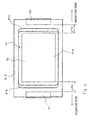
- laminated battery 1 includes: battery element 2 having an approximately rectangular shape and a configuration in which a plurality of positive electrode sheets and negative electrode sheets are stacked; positive electrode lead 3 and negative electrode lead 4 that are connected to the positive electrode sheets and negative electrode sheets, respectively, of battery element 2; and covering materials 5 and 6 for sealing battery element 2 while allowing a portion of each of positive electrode lead 3 and negative electrode lead 4 to protrude.
- laminated battery 1 is assumed to be a lithium-ion secondary battery.
- Battery element 2 is composed of a plurality of positive electrode sheets and a plurality of negative electrode sheets that are alternately stacked with interposed separators, and includes laminated electrode unit 2a, which contains an electrolyte and which is the portion in which these components are stacked, and positive electrode junction 2b and negative electrode junction 2c for connecting this laminated electrode unit 2a to positive electrode lead 3 and negative electrode lead 4, respectively.
- Positive electrode junction 2b and negative electrode junction 2c are portions that extend as a unit from the positive electrode sheets and negative electrode sheets, respectively that are the constituent elements of laminated electrode unit 2a.
- Positive electrode junction 2b and negative electrode junction 2c extend from opposite sides of battery element 2. In other words, positive electrode lead 3 and negative electrode lead 4 are led out in opposite directions from laminated battery 1. Explanation next regards the details of the construction of battery element 2.
- Separators may employ parts in sheet form such as a microporous film made from a thermoplastic resin such as polyolefin, a nonwoven fabric, or woven fabric that can be impregnated with electrolyte.
- a microporous film made from a thermoplastic resin such as polyolefin, a nonwoven fabric, or woven fabric that can be impregnated with electrolyte.
- Covering materials 5 and 6 are two pieces of laminated film that enclose battery element 2 from both sides in the direction of thickness, battery element 2 being sealed by heat-sealing the overlapping edges.
- covering materials 5 and 6 are each processed into a cup form having a brim so as to form a housing, which is the space in which battery element 2 is enclosed. This process can be realized by deep-draw forming.
- FIG. 1 an example is shown in which battery element 2 is enclosed by two pieces of covering material 5 and 6 from the two sides in the direction of thickness and then sealed by heat sealing the four edges, but the invention is not limited to this form, and a configuration is also possible in which covering material in the form of a single film is folded in two to enclose battery element 2, and battery element 2 is then sealed by heat-sealing the three open sides.
- the present embodiment assumes the use of a lithium-ion secondary battery, and the area of the portion in which a negative electrode material has been applied on negative electrode sheets is greater than the area of application of positive electrode material on positive electrode sheets.
- negative electrode material application edge 22a is positioned more toward the outside than positive electrode material application edge 12a.
- the amount of protrusion of negative electrode material application edge 22a from positive electrode material application edge 12a is preferably 0.5-2 mm.
- separator ends 31, which are the ends of separators 30, are positioned somewhat more toward the outside than negative electrode material application edge 22a.
- the amount of protrusion of separator ends 31 from negative electrode material application edge 22a is preferably 0.5-2 mm.
- Positive electrode sheets 10 are composed of aluminum foil and include positive collectors 11 in which a positive electrode material has been applied to the main portions of both surfaces of positive electrode sheets 10.
- the major portion of positive collector 11 in the region of laminated electrode unit 2a is constituted by positive electrode material applied portion 12 in which a positive electrode material has been applied to the two surfaces.
- Non-applied portion 13, which is a portion in which positive electrode material is not applied, extends from one side of positive collector 11.
- Non-applied portions 13 of each positive collector 11 are gathered together in a stacked form on positive electrode lead 3, which is composed of a metal plate, at a position that is a prescribed distance toward the outside from separator ends 31. Non-applied portions 13 are then connected together by welding. In determining the position of connection unit 40 between non-applied portions 13 of these positive collectors 11 and positive electrode lead 3, care must be exercised regarding the following points:
- the thickness first decreases by the thickness of application of the positive electrode material at the position of positive electrode material application edge 12a.
- the thickness next decreases by the thickness of negative electrode sheet 20 at negative electrode material application edge 22a, and further decreases by the thickness of separators 30 at separator ends 31.
- non-applied portions 13 alone are gathered together over positive electrode lead 3 to arrive at connection unit 40.
- Connection unit 40 is thus formed by gathering together positive collectors 11 that had the same spread (spacing) as the thickness of laminated electrode unit 2a and then contact-bonding or welding by ultrasonic welding.
- positive collectors 11 which are aluminum foil, are sharply bent at base 40a of connection unit 40 and therefore prone to breaks in the foil.
- ultrasonic welding in particular, ultrasonic oscillations are applied while placing the horn to the side of the softer part, and the anvil is therefore usually placed to the side of positive electrode lead 3 and the horn brought to the side of positive collector 11. Foil cracking in positive collectors 11 therefore tends to occur at the border of the horn.
- connection unit 40 To prevent foil breakage, the position of connection unit 40 should be sufficiently separated from laminated electrode unit 2a and the bend of positive collectors 11 thus limited. On the other hand, excessive distance from laminated electrode unit 2a to connection unit 40 leads to an increase in the overall size of the battery and detracts from the efficiency of the cubic volume. The position of connection unit 40 is therefore designed to achieve a balance between reliability against breakage and space efficiency.
- Negative electrode sheets 20 include negative collectors 21 that are composed of copper foil to which negative electrode material has been applied on both surfaces of the major portions.
- the major portion of negative collectors 21 is negative electrode material applied portion 22 in which negative electrode material has been applied to both surfaces in the area of laminated electrode unit 2a.
- the area of negative electrode material applied portion 22 is greater than the area of positive electrode material applied portion 12 in positive electrode sheets 10, and negative electrode material applied portion 22 therefore completely covers positive electrode material applied portion 12.
- Non-applied portions 23 are gathered together as a stack at a position that is a prescribed distance toward the outside from separator ends 31 over negative electrode lead 4 that is composed of a metal plate and then connected by welding.
- connection unit 41 When determining the position of connection unit 41 of non-applied portions 23 of these negative collectors 21 and negative electrode lead 4, the same care must be exercised as on the positive electrode side. In other words, the position of connection unit 41 is designed to achieve a balance between improving the efficiency of use of the cubic volume and solving the problem of foil breakage.
- sealant 51 is provided in the area of positive electrode lead 3 in which covering materials 5 and 6 of positive electrode lead 3 are heat-sealed for preventing a drop in the heat sealing characteristics due to the interposition of the metal plate when covering material 5 and 6 is heat-sealed.
- sealant 52 is also provided in the area of negative electrode lead 4 in which covering materials 5 and 6 are heat-sealed.
- connection units 40 and 41 on the positive electrode side and negative electrode side are covered by protective films 56 and 57, respectively.
- connection units 40 and 41 are preferably designed to produce the relation c ⁇ b, where "b" is the spacing between positive electrode material application edge 12a and base 40a of connection unit 40 in the direction of lead-out of positive electrode lead 3 in positive electrode junction 2b, and "c” is the spacing between the ends of positive electrode sheets 10 and base 41 a of connection unit 41 in the direction of lead-out of negative electrode lead 4 in negative electrode junction 2c.
- positive electrode material applied portion 12 was used as the standard for setting the position of connection unit 40 on the side of positive electrode lead 3 from the border of this positive electrode material applied portion 12 such that foil cracking of positive collectors 11 did not occur during ultrasonic welding.
- the position of connection unit 41 on the side of negative electrode lead 4 was then also set to the same spacing (the same spacing as the spacing from positive electrode material application edge 12a to base 40a of connection unit 40) that was set for the positive electrode side.
- connection unit 41 such that cracks do not occur in the foil of negative collectors 21
- connection unit 41 there is more margin in the direction that approaches laminated electrode unit 2a, and that the size from laminated electrode unit 2a to connection unit 41 on the negative electrode side (the size of negative electrode junction 2c) can be correspondingly reduced for an increase in space efficiency.
- connection units 40 and 41 allows a reduction of the size of the covering materials in the directions of lead-out of the leads and thus produces a significant effect.
- connection unit on the negative electrode side closer to the laminated electrode unit also enables a reduction of the cubic volume of the negative electrode junction in a laminated battery having a configuration in which the positive electrode lead and negative electrode lead are led out from a single side, and although this arrangement causes a variation in the outer form of lead-out portion of the lead on the positive electrode side and the lead-out portion of the lead on the negative electrode side, it allows an inside reduction equal in size to the covering materials in the lead-out portion of the lead on the negative electrode side.
- negative collectors 21 employ a thinner metal foil than the positive collectors 11, and the collectors on the negative electrode side are therefore easier to bend than the collectors on the positive electrode side.
- Connection unit 41 is therefore correspondingly easier to bring closer to the laminated electrode unit.
- negative electrode material application edge 22a on the side of positive electrode junction 2b is well defined because negative collector 21 to which negative electrode material has been applied is cut from above the applied film.
- the edge of the applied portion is formed by stopping the flow of the negative electrode compound with a shutter.
- the thickness of the edge of negative electrode material applied portion 22 does not change in sharp steps.
- the edge of the applied film has a tapered form with a skirt section of typically 0.5-2 mm.
- the thickness of negative electrode sheet 20 tends to be thin.
- negative electrode material film of prescribed thickness is formed as far as the edge and is therefore difficult to bend.
- negative electrode material applied portion 22 in the area that protrudes beyond positive electrode sheet 10 in FIG. 3 is easier to bend than the end of negative electrode sheet 20 on the positive electrode lead 3 side due to the reasons described above.
- negative electrode material applied portion 22 that is immediately outside positive electrode sheet 10 curves toward connection unit 41.
- negative electrode sheets 20 are pressed by covering materials 5 and 6 due to the atmospheric pressure when the battery is returned to atmospheric pressure after sealing.
- negative electrode material applied portion 22 bends toward the position of height of connection unit 41 in the direction of the thickness of battery element 2.
- separators 30 and non-applied portions 13 of positive collectors 11 are interposed between negative electrode sheets 20 at the ends of negative electrode sheets 20 on the positive electrode lead 3 side.
- separators 30 are formed from thin resin film and therefore bend easily. The ends of positive electrode sheets 10 therefore have large steps on the negative electrode lead 4 side and are easy to bend.
- the border of the area in which the constituent parts of laminated electrode unit 2a are difficult to bend tends to be at the edges of negative electrode sheets 20 on the positive electrode lead 3 side, and at the edges of positive electrode sheets 10 on the negative electrode lead 4 side.
- negative electrode sheets 20 are pressed by covering materials 5 and 6 due to atmospheric pressure when the battery is returned to atmospheric pressure after sealing.
- the border of the flat portion of the outer form of the battery at this time also tends to be located at the same position as the position described above.
- connection units 40 and 41 can be found if the dimensions of the position of connection unit 40 from the edges of negative electrode sheets 20 on the positive electrode lead 3 side and the position of connection unit 41 from the edges of positive electrode sheets 10 on the negative electrode lead 4 side are each taken as a standard and then designed such that foil cracking does not occur.
- the area of application of the negative electrode material is typically greater than the area of application of the positive electrode material. If design is implemented according to the above-described guiding principles, the relation c ⁇ b will inevitably result.
- connection units 40 and 41 can be designed optimally if the spacing "p" in FIG. 2 is preferably substantially the same dimension as spacing "c" that is shown in FIG. 3, where "p” is the spacing in the lead-out direction of positive electrode lead 3 between the edges of negative electrode sheets 20 and base 40a of connection unit 40 in positive electrode junction 2b.
- Spacing "p” need not be exactly the same as spacing “c” but can be adjusted within the range in which the above-described effect can be obtained. More specifically, when the dimension of "c” is designed by taking as a standard the dimension on the positive electrode lead 3 side in which foil breakage tends to occur, the possibility of foil breakage increases when “c” is 0.8 p or less, and the desired space efficiency effect becomes difficult to achieve when “c” is 1.2 p or more. Accordingly, the effects of the present invention can be obtained when "c” is within the range: 0.8 p ⁇ c ⁇ 1.2 p.
- FIG. 4 the preferable estimated position for accommodating the battery element and the preferable estimated position of lead-sealing sealant with respect to the covering material are shown by dotted lines.
- the position of cup 61 for the housing of battery element 2 is symmetrical on the positive electrode side and negative electrode side with respect to the outer shape of covering 5 and 6.
- the positional relations of sealant 51 and 52 with respect to laminated electrode unit 2a differ for the positive electrode side and negative electrode side, c+d being smaller than a+b in FIG. 4.
- "b” and "c” indicate the previously described spacing.
- “a” is the spacing from base 40a of connection unit 40 to sealant 51 on the positive electrode lead 3 side
- "d” is the spacing from base 41 a of connection unit 41 to sealant 52 on the negative electrode lead 4 side.
- the overall outer shape of battery element 2 can be considered as a flat portion that extends as far as the negative electrode edges on the positive electrode lead 3 side with the border of the flat portion dropping precipitously on the negative electrode lead 4 side but assuming a more gradual slope on the positive electrode lead 3 side.
- the position of laminated electrode unit 2a is biased toward the negative electrode side to facilitate matching of the flat portion of the outer form of battery element 2 with bottom surface 61 a of cup 61 of covering materials 5 and 6.
- cup 61 on covering materials 5 and 6 can be realized by deep-draw forming.
- the border portion between bottom surface 61a and side surface 61 b of cup 61 is slightly curved due to the shape of the punch at this time. Accordingly, if the curved portion of this cup 61 is taken into consideration when positioning battery element 2 in cup 61, the flat portion of battery element 2 is preferably set so as to be positioned on the inner side of the curved portion of the border between bottom surface 61 a and side surface 61b of cup 61.
- the material of the positive electrode lead and negative electrode lead aluminum, copper, nickel, titanium, iron, phosphor bronze, brass, stainless steel, nickel-plated copper, and nickel-plated aluminum may be used, and an annealing process may be applied as necessary.
- the thickness of the leads is preferably 0.08-1.0 mm.
- a surface treatment is preferably applied to at least those portions of the leads that are in close contact with the covering material to improve adhesion with the covering material.
- a surface treatment may take the form of: surface roughening realized by a chemical etching treatment; an oxide film treatment realized by electrolytic formation; formation of a coating composed of partially aminated phenol polymer, a phosphorylated compound, and a titanium compound; a corrosion-resistant coating foundation treatment realized by a zinc phosphate coating; and a surface treatment realized by, for example, a titanium coupling agent or aluminate coupling agent.
- a resin film that contains a metal-adhesive resin is preferably fused to the leads in advance.
- a substance that adheres to the surfaces of the lead terminals, which are metal plates, is employed as the metal-adhesive resin, examples of such a substance including: acid modified polypropylene, acid modified polyethylene, acid modified poly (ethylene-propylene) copolymer, or ionomer.
- the covering material no particular limitations are imposed on the material used as long as the material is flexible and can cover the battery main element such that electrolyte does not leak.
- One material that is particularly preferable as the covering material is a laminated film in which a metal layer and a heat-sealable resin layer are laminated.
- heat-sealable resin is applied to a thickness of 3 ⁇ m-200 ⁇ m to a metal foil having a thickness of 10 ⁇ m-100 ⁇ m.
- Examples of materials that can be offered as the material of the metal foil include: aluminum, titanium, titanium alloy, iron, stainless steel, and magnesium alloy.
- Materials that can be used as the heat-sealable resin include: polypropylene, polyethylene, acid modified products of these materials, polyesters such as polyphenylene sulfide, polyethylene terephthalate, polyamide, and ethylene-vinyl acetate copolymer.
- the cup that forms the housing of the battery element may be formed on the covering material on both surfaces in the direction of thickness of the battery element, or may be formed on only one surface.
- a configuration may also be adopted in which the battery element is sealed not by forming a cup in the covering material, but by taking advantage of the flexibility of the covering material. In this case, the covering material is deformed to conform to the outer form of the battery element.
- Positive Electrodes and Negative Electrodes Regarding the positive electrode, no particular limitations are imposed as long as the positive electrode is an element that absorbs positive ions or that emits negative ions during discharge, and a material that is known as a conventional material for the positive electrode in a secondary battery can be used, examples of which include:
- the material of the negative electrode no particular limitations are imposed as long as the material is capable of occluding and discharging cations.
- Materials that can be used include natural graphite, crystalline carbon such as graphitized carbon that is obtained by subjecting coal/petroleum pitch to a high-temperature heat treatment; or amorphous carbon that is obtained by subjecting coal, petroleum pitch coke, or acetylene pitch coke to a heat treatment.
- salts that are composed of the cations of alkali metals such as lithium, potassium, and sodium and the anions of compounds that contain halogen such as CIO 4 - , BF 4 - , PF 6 - , CF 3 SO 3 - , (CF 3 SO 2 ) 2 N - , (C 2 F 5 SO 2 ) 2 N - , (CF 3 SO 2 ) 3 C - , and (C 2 F 5 SO 2 ) 3 C - are dissolved in a basic solvent having a high polarity and that can be used as the electrolyte of a secondary battery, such as ethylene carbonate, propylene carbonate, dimethyl carbonate, diethyl carbonate, methyl ethyl carbonate, ⁇ -butyrolactone, N,N'-dimethyl .
- the above-described materials relate to a lithium-ion secondary battery, but the present invention may also be applied to a lead battery, a nickel-cadmium battery, and a nickel-hydrogen battery.
- the present invention can be applied not only to batteries, but also to electric double-layer capacitors and nonaqueous electrolytic capacitors.
- a positive electrode mixture containing lithium manganate powder having a spinel structure is applied by means of a doctor blade to both surfaces of aluminum foil having a thickness of 20 ⁇ m that is to serve as a positive collector, whereby the overall thickness becomes 125 ⁇ m.
- a non-applied portion (a portion in which the positive collector is exposed) is also formed by intermittent application of the positive electrode mixture, this application being realized by opening and closing a shutter.
- This assembly is cut into positive electrode sheets having a rectangular shape that measures, including the portion in which the positive electrode mixture is not applied, 137 mm x 65 mm. Thirty-two positive electrode sheets that are obtained in this way are prepared.
- the size of the positive electrode material applied portion is 120 mm x 65 mm, and the area is 7800 mm 2 .
- the lead-out length of the portion in which the positive electrode mixture is not applied is 17 mm at this stage, but as will later be explained, this portion is uniformly cut after formation of the laminated electrode body and will therefore be shorter.
- a negative electrode mixture that contains amorphous carbon powder is applied by means of a doctor blade to both surfaces of copper foil that is to be the negative collector and that has a thickness of 10 ⁇ m, whereby the overall thickness reaches 115 ⁇ m.
- This assembly is cut into negative electrode sheets having a rectangular shape that measures, including the portion in which the negative electrode mixture is not applied, 137 mm ⁇ 69 mm. Thirty-three negative electrode sheets that have been obtained in this way are prepared.
- the size of the negative electrode material applied portion is 124 mm ⁇ 69 mm, and the area of this portion is 8556 mm 2 .
- the lead-out length of the portion in which the negative electrode mixture is not applied is 13 mm at this stage, but as will be explained later, the sheets are uniformly cut after formation of the laminated electrode body and will therefore be shorter.
- the positive electrode sheets and negative electrode sheets that have been prepared as described above are alternately stacked with interposed separators, these separators each being composed of a microporous film made from polypropylene and having a thickness of 25 ⁇ m, such that the outermost layers are negative electrode sheets, whereby a laminated electrode body is obtained.
- the directions of the positive electrode sheets and the negative electrode sheets are arranged such that the portions in which the positive electrode mixture has not been applied and the portions in which the negative electrode mixture has not been applied are oriented toward opposite sides.
- the dimensional design and positioning of the separators is realized such that the separators protrude 2 mm on each of the four edges from the area in which the negative electrode material has been applied.
- the non-applied portions of the positive and negative electrodes are each gathered together at the respective intended connection points and held down by a clip.
- the non-applied portions of the positive electrode sheets are collectively cut all together and aligned at the position at which the lead-out distance, for the center in the direction of lamination of the positive electrode sheets, is 12.5 mm, the lead-out distance being measured from the edge of the portion in which the positive electrode mixture has been applied.
- the negative electrode sheets are similarly collectively severed and thus aligned at the position at which the lead-out distance is 8.5 mm from the edge of the portion in which the negative electrode mixture has been applied for the center in the direction of lamination of the negative electrode sheets.
- the portions to which the positive electrode material has not been applied of the 32 positive electrode sheets are collected on an aluminum plate having a thickness of 0.1 mm that is to be the positive electrode lead, a horn is placed to the positive electrode material non-applied portion side, and ultrasonic welding is carried out.
- the portions to which the negative electrode material has not been applied of the 33 negative electrode sheets are collected together on a nickel plate having a thickness of 0.1 mm that is to be the negative electrode lead, a horn is brought to the negative electrode material non-applied portion side, and ultrasonic welding is carried out.
- a sealant composed of modified polypropylene is heat-sealed to the positive electrode lead and the negative electrode lead.
- a 5.5 mm
- b 8.5 mm
- p 6.5 mm
- c 6.5 mm
- d 5.5 mm.
- the length of positive electrode junction 2b in the direction of lead-out of the lead is 12.5 mm
- the length of negative electrode junction 2c is 10.5 mm (of this dimension, the negative electrode mixture has been applied to 2 mm).
- the lead-out side of portions in which the negative electrode material was not applied (hereinbelow referred to as simply "negative electrode side") in the vicinity of the border with the portion in which the negative electrode was applied curves in the direction of the portion that is welded to the negative electrode lead.
- the above-described laminated electrode body containing an electrolyte was next housed within covering materials having the outer form shown in FIG. 4 (a shape that is symmetrical on the positive and negative electrode sides) and then vacuum-sealed.
- the covering materials were laminated films of an aluminum layer having a thickness of 40 ⁇ m and a polypropylene resin layer having a thickness of 40 ⁇ m that was formed in cup shape by deep-draw forming.
- the laminated electrode unit was biased toward the negative electrode side while the position of the sealant, taking the covering materials as a reference, was matched to the same position on the positive electrode side as on the negative electrode side, as shown in FIG. 4.
- the spacing from the positive electrode material applied portions to the end of the cup bottom surface of the covering was 4 mm on the positive electrode side and 2 mm on the negative electrode side. Appropriate determination of the depth of the cup enabled a smooth outer surface without the occurrence of wrinkles in the covering material even in vacuum-sealing.
Landscapes
- Chemical & Material Sciences (AREA)
- Chemical Kinetics & Catalysis (AREA)
- Electrochemistry (AREA)
- General Chemical & Material Sciences (AREA)
- Engineering & Computer Science (AREA)
- Manufacturing & Machinery (AREA)
- Materials Engineering (AREA)
- Connection Of Batteries Or Terminals (AREA)
- Secondary Cells (AREA)
- Sealing Battery Cases Or Jackets (AREA)
- Cell Electrode Carriers And Collectors (AREA)
Applications Claiming Priority (2)
| Application Number | Priority Date | Filing Date | Title |
|---|---|---|---|
| JP2003377236A JP3972205B2 (ja) | 2003-11-06 | 2003-11-06 | 積層型電池 |
| JP2003377236 | 2003-11-06 |
Publications (3)
| Publication Number | Publication Date |
|---|---|
| EP1530246A2 true EP1530246A2 (fr) | 2005-05-11 |
| EP1530246A3 EP1530246A3 (fr) | 2007-02-21 |
| EP1530246B1 EP1530246B1 (fr) | 2011-02-09 |
Family
ID=34431318
Family Applications (1)
| Application Number | Title | Priority Date | Filing Date |
|---|---|---|---|
| EP04090423A Active EP1530246B1 (fr) | 2003-11-06 | 2004-11-05 | Batterie laminée |
Country Status (6)
| Country | Link |
|---|---|
| US (1) | US20050100784A1 (fr) |
| EP (1) | EP1530246B1 (fr) |
| JP (1) | JP3972205B2 (fr) |
| KR (1) | KR100633196B1 (fr) |
| CN (1) | CN100353592C (fr) |
| DE (1) | DE602004031321D1 (fr) |
Cited By (1)
| Publication number | Priority date | Publication date | Assignee | Title |
|---|---|---|---|---|
| EP1876668A2 (fr) * | 2006-07-06 | 2008-01-09 | Enax, Inc. | Batterie secondaire stratifiée et son procédé de fabrication |
Families Citing this family (24)
| Publication number | Priority date | Publication date | Assignee | Title |
|---|---|---|---|---|
| US6303500B1 (en) * | 1999-02-24 | 2001-10-16 | Micron Technology, Inc. | Method and apparatus for electroless plating a contact pad |
| JP5076464B2 (ja) | 2005-12-12 | 2012-11-21 | Tdk株式会社 | リチウムイオン二次電池 |
| JP2007213820A (ja) * | 2006-02-07 | 2007-08-23 | Hitachi Vehicle Energy Ltd | 二次電池 |
| KR100895202B1 (ko) * | 2006-04-17 | 2009-05-06 | 주식회사 엘지화학 | 파우치형 전지 |
| TW200742150A (en) * | 2006-04-19 | 2007-11-01 | Exa Energy Technology Co Ltd | Method for producing secondary battery |
| KR100874385B1 (ko) | 2006-07-10 | 2008-12-18 | 주식회사 엘지화학 | 이차전지용 안전부재 |
| JP4501905B2 (ja) * | 2006-07-19 | 2010-07-14 | トヨタ自動車株式会社 | 組電池 |
| KR100888284B1 (ko) | 2006-07-24 | 2009-03-10 | 주식회사 엘지화학 | 탭-리드 결합부의 전극간 저항차를 최소화한 전극조립체 및이를 포함하고 있는 전기화학 셀 |
| JP5354646B2 (ja) * | 2008-07-31 | 2013-11-27 | Necエナジーデバイス株式会社 | 積層型二次電池およびその製造方法 |
| JP5348473B2 (ja) * | 2009-01-20 | 2013-11-20 | ソニー株式会社 | 液晶表示装置および電子機器 |
| TWI424604B (zh) * | 2009-05-20 | 2014-01-21 | Nec Energy Devices Ltd | A method for producing a laminate type secondary battery and laminate type secondary batteries |
| KR101049826B1 (ko) | 2009-11-23 | 2011-07-15 | 삼성에스디아이 주식회사 | 리튬 이차 전지용 양극, 이의 제조 방법 및 이를 포함하는 리튬 이차 전지 |
| DE102010014700A1 (de) * | 2010-04-12 | 2011-10-13 | Ke-Tec Gmbh | Folienableiter für Flachzellen und Verfahren zu dessen Herstellung |
| JP5527176B2 (ja) * | 2010-11-25 | 2014-06-18 | ソニー株式会社 | 非水電解質電池 |
| CN106910941A (zh) | 2012-09-27 | 2017-06-30 | Nec能源元器件株式会社 | 锂离子二次电池及其制作方法 |
| JP6229709B2 (ja) * | 2013-02-28 | 2017-11-15 | 日産自動車株式会社 | 正極活物質、正極材料、正極および非水電解質二次電池 |
| KR102073192B1 (ko) * | 2013-08-07 | 2020-02-04 | 삼성에스디아이 주식회사 | 파우치형 배터리셀 |
| KR101800932B1 (ko) * | 2015-03-16 | 2017-11-23 | 주식회사 엘지화학 | 스텝드 배터리 |
| JP6767846B2 (ja) * | 2016-01-12 | 2020-10-14 | セイコーインスツル株式会社 | 電気化学セルおよび電気化学セルの製造方法 |
| US10916798B2 (en) * | 2016-01-12 | 2021-02-09 | Seiko Instruments Inc. | Electrochemical cell and manufacturing method of electrochemical cell |
| WO2017145212A1 (fr) * | 2016-02-24 | 2017-08-31 | パナソニックIpマネジメント株式会社 | Batterie mince |
| JP6607225B2 (ja) * | 2017-04-13 | 2019-11-20 | トヨタ自動車株式会社 | 積層型電池 |
| US10673028B2 (en) * | 2017-09-28 | 2020-06-02 | Maxwell Holdings, Ltd. | Electrochemical element |
| JP2021051944A (ja) * | 2019-09-25 | 2021-04-01 | 積水化学工業株式会社 | 蓄電素子及び蓄電素子の製造方法 |
Citations (3)
| Publication number | Priority date | Publication date | Assignee | Title |
|---|---|---|---|---|
| US20020146620A1 (en) * | 2001-04-06 | 2002-10-10 | Ntk Powerdex, Inc. | Method of joining current collectors in a multi-layer cell |
| EP1333520A2 (fr) * | 2002-02-01 | 2003-08-06 | Nec Corporation | Pile plate et batterie combinée l'utilisant |
| CA2384215A1 (fr) * | 2002-04-30 | 2003-10-30 | Richard Laliberte | Faisceau electrochimique et methode de fabrication dudit faisceau |
Family Cites Families (8)
| Publication number | Priority date | Publication date | Assignee | Title |
|---|---|---|---|---|
| JPH07282841A (ja) * | 1994-04-05 | 1995-10-27 | Mitsubishi Chem Corp | リチウムイオン二次電池 |
| JPH09288998A (ja) * | 1996-04-23 | 1997-11-04 | Sumitomo Electric Ind Ltd | 非水電解質電池 |
| CA2207801C (fr) * | 1996-06-19 | 2004-03-30 | Hideki Kaido | Pile a electrolyte non aqueux |
| JP3210593B2 (ja) * | 1997-02-17 | 2001-09-17 | 日本碍子株式会社 | リチウム二次電池 |
| JPH11250873A (ja) | 1998-02-27 | 1999-09-17 | Japan Storage Battery Co Ltd | 非水電解質二次電池 |
| JP2001126678A (ja) * | 1999-10-28 | 2001-05-11 | Hitachi Maxell Ltd | 積層形ポリマー電解質電池 |
| JP2001332241A (ja) | 2000-05-23 | 2001-11-30 | Sony Corp | 薄型電池 |
| CN1263184C (zh) * | 2001-11-20 | 2006-07-05 | Tdk株式会社 | 电极活性材料及其制法、电极、锂离子二次电池及其制法 |
-
2003
- 2003-11-06 JP JP2003377236A patent/JP3972205B2/ja not_active Expired - Lifetime
-
2004
- 2004-11-04 KR KR1020040089159A patent/KR100633196B1/ko active IP Right Grant
- 2004-11-05 US US10/981,625 patent/US20050100784A1/en not_active Abandoned
- 2004-11-05 DE DE602004031321T patent/DE602004031321D1/de active Active
- 2004-11-05 EP EP04090423A patent/EP1530246B1/fr active Active
- 2004-11-08 CN CNB2004100883167A patent/CN100353592C/zh active Active
Patent Citations (3)
| Publication number | Priority date | Publication date | Assignee | Title |
|---|---|---|---|---|
| US20020146620A1 (en) * | 2001-04-06 | 2002-10-10 | Ntk Powerdex, Inc. | Method of joining current collectors in a multi-layer cell |
| EP1333520A2 (fr) * | 2002-02-01 | 2003-08-06 | Nec Corporation | Pile plate et batterie combinée l'utilisant |
| CA2384215A1 (fr) * | 2002-04-30 | 2003-10-30 | Richard Laliberte | Faisceau electrochimique et methode de fabrication dudit faisceau |
Cited By (2)
| Publication number | Priority date | Publication date | Assignee | Title |
|---|---|---|---|---|
| EP1876668A2 (fr) * | 2006-07-06 | 2008-01-09 | Enax, Inc. | Batterie secondaire stratifiée et son procédé de fabrication |
| EP1876668A3 (fr) * | 2006-07-06 | 2010-11-03 | Enax, Inc. | Batterie secondaire stratifiée et son procédé de fabrication |
Also Published As
| Publication number | Publication date |
|---|---|
| DE602004031321D1 (de) | 2011-03-24 |
| CN100353592C (zh) | 2007-12-05 |
| EP1530246B1 (fr) | 2011-02-09 |
| JP2005142028A (ja) | 2005-06-02 |
| KR20050043660A (ko) | 2005-05-11 |
| JP3972205B2 (ja) | 2007-09-05 |
| KR100633196B1 (ko) | 2006-10-11 |
| US20050100784A1 (en) | 2005-05-12 |
| CN1614798A (zh) | 2005-05-11 |
| EP1530246A3 (fr) | 2007-02-21 |
Similar Documents
| Publication | Publication Date | Title |
|---|---|---|
| EP1530246B1 (fr) | Batterie laminée | |
| KR100790631B1 (ko) | 필름 외장 전기 디바이스 및 해당 필름 외장 전기디바이스용의 집전부 피복부재 | |
| JP3789439B2 (ja) | フィルム外装積層型組電池 | |
| EP3101723B1 (fr) | Pile rechargeable et procédé de fabrication de pile rechargeable | |
| JP5256589B2 (ja) | フィルム外装電池が複数隣接して配置された組電池 | |
| KR101867374B1 (ko) | 전극 단자를 구비한 배터리 덮개, 전극 단자를 구비한 배터리 덮개 제조 방법 및 실링된 배터리 | |
| US20120202105A1 (en) | Stack type battery and method of manufacturing the same | |
| US10490841B2 (en) | Secondary battery | |
| US20110076544A1 (en) | Stack type battery | |
| EP3010069B1 (fr) | Batterie secondaire | |
| US8614015B2 (en) | Secondary battery and method of manufacturing secondary battery | |
| CN111630699B (zh) | 二次电池 | |
| KR101821488B1 (ko) | 전지 | |
| KR100731436B1 (ko) | 파우치형 리튬 이차 전지 | |
| JP5472284B2 (ja) | フィルム外装電池及び組電池 | |
| JP2004031161A (ja) | 組電池 | |
| JP6970912B2 (ja) | 蓄電素子、及び蓄電素子を備える蓄電装置 | |
| KR100635759B1 (ko) | 파우치형 리튬 이차 전지 | |
| KR20180035510A (ko) | 전극 조립체 및 이를 포함하는 이차 전지 | |
| CN113924674A (zh) | 二次电池 | |
| JP2003331799A (ja) | 組電池 | |
| JP2004031162A (ja) | 組電池 |
Legal Events
| Date | Code | Title | Description |
|---|---|---|---|
| PUAI | Public reference made under article 153(3) epc to a published international application that has entered the european phase |
Free format text: ORIGINAL CODE: 0009012 |
|
| AK | Designated contracting states |
Kind code of ref document: A2 Designated state(s): AT BE BG CH CY CZ DE DK EE ES FI FR GB GR HU IE IS IT LI LU MC NL PL PT RO SE SI SK TR |
|
| AX | Request for extension of the european patent |
Extension state: AL HR LT LV MK YU |
|
| RIN1 | Information on inventor provided before grant (corrected) |
Inventor name: MIZUTA, MASATOMO Inventor name: OTOHATA, MAKIHIRO Inventor name: YAGETA, HIROSHI |
|
| RAP1 | Party data changed (applicant data changed or rights of an application transferred) |
Owner name: NEC LAMILION ENERGY, LTD. |
|
| PUAL | Search report despatched |
Free format text: ORIGINAL CODE: 0009013 |
|
| AK | Designated contracting states |
Kind code of ref document: A3 Designated state(s): AT BE BG CH CY CZ DE DK EE ES FI FR GB GR HU IE IS IT LI LU MC NL PL PT RO SE SI SK TR |
|
| AX | Request for extension of the european patent |
Extension state: AL HR LT LV MK YU |
|
| RIC1 | Information provided on ipc code assigned before grant |
Ipc: H01M 10/04 20060101ALI20070117BHEP Ipc: H01M 2/26 20060101AFI20070117BHEP |
|
| RAP1 | Party data changed (applicant data changed or rights of an application transferred) |
Owner name: NEC CORPORATION |
|
| 17P | Request for examination filed |
Effective date: 20070315 |
|
| AKX | Designation fees paid |
Designated state(s): DE FR IT |
|
| GRAP | Despatch of communication of intention to grant a patent |
Free format text: ORIGINAL CODE: EPIDOSNIGR1 |
|
| GRAS | Grant fee paid |
Free format text: ORIGINAL CODE: EPIDOSNIGR3 |
|
| GRAA | (expected) grant |
Free format text: ORIGINAL CODE: 0009210 |
|
| AK | Designated contracting states |
Kind code of ref document: B1 Designated state(s): DE FR IT |
|
| REF | Corresponds to: |
Ref document number: 602004031321 Country of ref document: DE Date of ref document: 20110324 Kind code of ref document: P |
|
| REG | Reference to a national code |
Ref country code: DE Ref legal event code: R096 Ref document number: 602004031321 Country of ref document: DE Effective date: 20110324 |
|
| PLBE | No opposition filed within time limit |
Free format text: ORIGINAL CODE: 0009261 |
|
| STAA | Information on the status of an ep patent application or granted ep patent |
Free format text: STATUS: NO OPPOSITION FILED WITHIN TIME LIMIT |
|
| 26N | No opposition filed |
Effective date: 20111110 |
|
| REG | Reference to a national code |
Ref country code: DE Ref legal event code: R097 Ref document number: 602004031321 Country of ref document: DE Effective date: 20111110 |
|
| REG | Reference to a national code |
Ref country code: FR Ref legal event code: PLFP Year of fee payment: 12 |
|
| REG | Reference to a national code |
Ref country code: FR Ref legal event code: PLFP Year of fee payment: 13 |
|
| REG | Reference to a national code |
Ref country code: FR Ref legal event code: PLFP Year of fee payment: 14 |
|
| REG | Reference to a national code |
Ref country code: FR Ref legal event code: PLFP Year of fee payment: 15 |
|
| REG | Reference to a national code |
Ref country code: DE Ref legal event code: R079 Ref document number: 602004031321 Country of ref document: DE Free format text: PREVIOUS MAIN CLASS: H01M0002060000 Ipc: H01M0050172000 |
|
| PGFP | Annual fee paid to national office [announced via postgrant information from national office to epo] |
Ref country code: IT Payment date: 20231124 Year of fee payment: 20 Ref country code: FR Payment date: 20231120 Year of fee payment: 20 Ref country code: DE Payment date: 20231121 Year of fee payment: 20 |