EP1530207B1 - Optische Abtastvorrichtung mit Korrekturelement - Google Patents
Optische Abtastvorrichtung mit Korrekturelement Download PDFInfo
- Publication number
- EP1530207B1 EP1530207B1 EP04256727A EP04256727A EP1530207B1 EP 1530207 B1 EP1530207 B1 EP 1530207B1 EP 04256727 A EP04256727 A EP 04256727A EP 04256727 A EP04256727 A EP 04256727A EP 1530207 B1 EP1530207 B1 EP 1530207B1
- Authority
- EP
- European Patent Office
- Prior art keywords
- light
- chromatic aberration
- light flux
- wavelength
- converging
- Prior art date
- Legal status (The legal status is an assumption and is not a legal conclusion. Google has not performed a legal analysis and makes no representation as to the accuracy of the status listed.)
- Expired - Lifetime
Links
- 230000003287 optical effect Effects 0.000 title claims description 315
- 230000004907 flux Effects 0.000 claims description 239
- 230000004075 alteration Effects 0.000 claims description 221
- 230000000694 effects Effects 0.000 claims description 11
- 239000000758 substrate Substances 0.000 claims description 11
- 230000001681 protective effect Effects 0.000 claims description 8
- 239000004065 semiconductor Substances 0.000 description 18
- 239000011241 protective layer Substances 0.000 description 11
- 238000010586 diagram Methods 0.000 description 8
- 230000008859 change Effects 0.000 description 7
- 239000000463 material Substances 0.000 description 7
- 102100040678 Programmed cell death protein 1 Human genes 0.000 description 6
- 238000012937 correction Methods 0.000 description 5
- 101710089372 Programmed cell death protein 1 Proteins 0.000 description 4
- 201000009310 astigmatism Diseases 0.000 description 3
- 238000005516 engineering process Methods 0.000 description 3
- 101000836337 Homo sapiens Probable helicase senataxin Proteins 0.000 description 2
- 101000615747 Homo sapiens tRNA-splicing endonuclease subunit Sen2 Proteins 0.000 description 2
- 102100027178 Probable helicase senataxin Human genes 0.000 description 2
- 238000013461 design Methods 0.000 description 2
- 102100021774 tRNA-splicing endonuclease subunit Sen2 Human genes 0.000 description 2
- 230000006872 improvement Effects 0.000 description 1
- 238000000034 method Methods 0.000 description 1
- 230000009467 reduction Effects 0.000 description 1
- 238000012827 research and development Methods 0.000 description 1
Images


Classifications
-
- G—PHYSICS
- G11—INFORMATION STORAGE
- G11B—INFORMATION STORAGE BASED ON RELATIVE MOVEMENT BETWEEN RECORD CARRIER AND TRANSDUCER
- G11B7/00—Recording or reproducing by optical means, e.g. recording using a thermal beam of optical radiation by modifying optical properties or the physical structure, reproducing using an optical beam at lower power by sensing optical properties; Record carriers therefor
- G11B7/12—Heads, e.g. forming of the optical beam spot or modulation of the optical beam
- G11B7/135—Means for guiding the beam from the source to the record carrier or from the record carrier to the detector
- G11B7/1372—Lenses
- G11B7/1378—Separate aberration correction lenses; Cylindrical lenses to generate astigmatism; Beam expanders
-
- G—PHYSICS
- G11—INFORMATION STORAGE
- G11B—INFORMATION STORAGE BASED ON RELATIVE MOVEMENT BETWEEN RECORD CARRIER AND TRANSDUCER
- G11B7/00—Recording or reproducing by optical means, e.g. recording using a thermal beam of optical radiation by modifying optical properties or the physical structure, reproducing using an optical beam at lower power by sensing optical properties; Record carriers therefor
- G11B7/12—Heads, e.g. forming of the optical beam spot or modulation of the optical beam
- G11B7/135—Means for guiding the beam from the source to the record carrier or from the record carrier to the detector
- G11B7/1353—Diffractive elements, e.g. holograms or gratings
-
- G—PHYSICS
- G11—INFORMATION STORAGE
- G11B—INFORMATION STORAGE BASED ON RELATIVE MOVEMENT BETWEEN RECORD CARRIER AND TRANSDUCER
- G11B7/00—Recording or reproducing by optical means, e.g. recording using a thermal beam of optical radiation by modifying optical properties or the physical structure, reproducing using an optical beam at lower power by sensing optical properties; Record carriers therefor
- G11B7/12—Heads, e.g. forming of the optical beam spot or modulation of the optical beam
- G11B7/125—Optical beam sources therefor, e.g. laser control circuitry specially adapted for optical storage devices; Modulators, e.g. means for controlling the size or intensity of optical spots or optical traces
- G11B7/127—Lasers; Multiple laser arrays
- G11B7/1275—Two or more lasers having different wavelengths
-
- G—PHYSICS
- G11—INFORMATION STORAGE
- G11B—INFORMATION STORAGE BASED ON RELATIVE MOVEMENT BETWEEN RECORD CARRIER AND TRANSDUCER
- G11B7/00—Recording or reproducing by optical means, e.g. recording using a thermal beam of optical radiation by modifying optical properties or the physical structure, reproducing using an optical beam at lower power by sensing optical properties; Record carriers therefor
- G11B7/12—Heads, e.g. forming of the optical beam spot or modulation of the optical beam
- G11B7/135—Means for guiding the beam from the source to the record carrier or from the record carrier to the detector
- G11B7/1372—Lenses
- G11B7/1374—Objective lenses
-
- G—PHYSICS
- G11—INFORMATION STORAGE
- G11B—INFORMATION STORAGE BASED ON RELATIVE MOVEMENT BETWEEN RECORD CARRIER AND TRANSDUCER
- G11B7/00—Recording or reproducing by optical means, e.g. recording using a thermal beam of optical radiation by modifying optical properties or the physical structure, reproducing using an optical beam at lower power by sensing optical properties; Record carriers therefor
- G11B7/12—Heads, e.g. forming of the optical beam spot or modulation of the optical beam
- G11B7/135—Means for guiding the beam from the source to the record carrier or from the record carrier to the detector
- G11B7/139—Numerical aperture control means
-
- G—PHYSICS
- G11—INFORMATION STORAGE
- G11B—INFORMATION STORAGE BASED ON RELATIVE MOVEMENT BETWEEN RECORD CARRIER AND TRANSDUCER
- G11B7/00—Recording or reproducing by optical means, e.g. recording using a thermal beam of optical radiation by modifying optical properties or the physical structure, reproducing using an optical beam at lower power by sensing optical properties; Record carriers therefor
- G11B7/12—Heads, e.g. forming of the optical beam spot or modulation of the optical beam
- G11B7/135—Means for guiding the beam from the source to the record carrier or from the record carrier to the detector
- G11B7/1392—Means for controlling the beam wavefront, e.g. for correction of aberration
- G11B7/13922—Means for controlling the beam wavefront, e.g. for correction of aberration passive
-
- G—PHYSICS
- G11—INFORMATION STORAGE
- G11B—INFORMATION STORAGE BASED ON RELATIVE MOVEMENT BETWEEN RECORD CARRIER AND TRANSDUCER
- G11B7/00—Recording or reproducing by optical means, e.g. recording using a thermal beam of optical radiation by modifying optical properties or the physical structure, reproducing using an optical beam at lower power by sensing optical properties; Record carriers therefor
- G11B2007/0003—Recording, reproducing or erasing systems characterised by the structure or type of the carrier
- G11B2007/0006—Recording, reproducing or erasing systems characterised by the structure or type of the carrier adapted for scanning different types of carrier, e.g. CD & DVD
Definitions
- the present invention relates to an optical pickup device and to a correcting element used in the optical pickup device.
- the high density optical disc there are known, for example, the one wherein an image-side numerical aperture of an objective lens (NA) is about 0.85 and a protective substrate thickness is about 0.1 mm and the one wherein NA and a protective substrate thickness are controlled to be respectively about 0.65 and about 0.6 mm which are similar to those of a conventional DVD (digital versatile disc).
- NA objective lens
- a protective substrate thickness is about 0.1 mm
- the high density optical disc whose NA and protective substrate thickness are respectively about 0.65 and about 0.6 mm will be indicated as "HD-DVD (High Density DVD)".
- light flux wavelengths ⁇ 1, ⁇ 2 and ⁇ 3 used respectively for HD-DVD, DVD and CD are respectively about 400 nm, about 650 nm and about 780 nm, and protective substrate thickness t1, t2 and t3 are respectively about 0.6 mm, about 0.6 mm and about 1.2 mm.
- Japanese laid-open patent No. 2001-60336 discloses a technology to provide a diffractive structure on an optical surface of an optical element that constitutes an optical pickup device.
- the invention disclosed in Japanese laid-open patent No. 2001-60336 is an optical pickup device having an compatibility between HD-DVD and DVD or an compatibility among HD-DVD, DVD and CD, wherein chromatic aberration of HD-DVD is corrected by combining a diffractive optical element and an objective lens.
- US-B-6 370 103 which is used for the two-part form delimitation, discloses a system for reproducing information from one of different kinds of optical information recording medium, each having a transparent substrate in different thickness.
- the system disclosed comprises a light source for omitting light flux, a converging optical system having an optical axis, a ring-zonal diffraction section, and a refracting surface including a first divisional portion, a second divisional portion and a third divisional portion.
- the first divisional portion and the third divisional portion are capable of converging the light flux on a first information recording plane of a first optical information recording medium having a first transparent substrate of thickness t1, to reproduce information recorded in the first optical information recording medium.
- the first divisional portion and the second divisional portion are capable of converging the light flux on a second information recording plane of a second optical information recording medium having a second transparent substrate of thickness t2, to reproduce information recorded in the second optical information recording medium, wherein t2 is greater than t1.
- WO-A-03075267 discloses a system for recording or reproducing conventional optical disks such as CDs and DVDs at high light usage efficiency, using an optical head capable of recording or reproduce high-density optical discs.
- a diffraction optical element is disposed in a light path of a first light beam of a first wavelength (400 nm to 415 nm) and a second light beam of a second wavelength (650 nm to 680 nm).
- An arrangement is disclosed in which principally fifth order diffracted light is emitted with respect to the first light beam and principally third order diffracted light is emitted with respect to the second light beam, from the diffraction optical element.
- a light diffraction efficiency of substantially 100% can be obtained with respect to both wavelengths.
- US-A-2001/036,018 discloses an optical element comprising an optical surface provided with a stepped level difference, wherein when the stepped level difference is viewed from a direction of an optical axis, the stepped level difference is provided in a form of a single continuous line in which a starting point of the line does not agree with an ending point of the line.
- an object of the invention is to provide an optical pickup device wherein at least a high density disc such as HD-DVD is compatible with DVD, and securing an amount of light is compatible with correction of chromatic aberration and to provide a correcting element representing an optical system used for the aforementioned optical pickup device.
- the "chromatic aberration” means the one wherein an amount of the position change for the minimum wavefront aberration in the optical axis direction for the light-converging spot on the optical information recording medium in the case of the change of a wavelength of light by +1 ⁇ m is indicated using the sign in which the direction to leave the light-converging optical element is positive.
- the "chromatic aberration owned by the element itself” is in the case of evaluating on the individual element, and it means the one wherein an amount of fluctuation of the position for the minimum wavefront aberration in the optical axis direction for the light-converging spot in the case of the change of a wavelength of light by +1 ⁇ m is indicated using the sign in which the direction to leave the light-converging optical element is positive.
- the "image-surface-side numerical aperture” means a numerical aperture (beam-diameter-converted NA) obtained by diameter of the light-converging spot formed on an information recording surface of the optical information recording medium.
- a demand for correction of chromatic aberration in DVD is lower, and therefore, no diffractive structure is provided on second correcting element L2 as in the second invention, and it is possible to control chromatic aberration of the second light-converging spot to be within a range necessary for reproducing and/or recording of information, even in the case of the structure in which the second correcting element itself has chromatic aberration for the second light flux.
- a large amount of light can be secured because for the second light flux it is not case that an amount of light is lost in passing through diffractive ring-shaped zones.
- the second correcting element is provided with a diffractive structure, and that an absolute value of chromatic aberration owned by the second correcting element itself is controlled to be 3.5 ⁇ m/nm or less for the light flux emitted from the second light source. In this way, worse of wavefront aberration can be suppressed, even when wavelength change are caused in the case of tracking in reproducing and/or recording for DVD, by controlling chromatic aberration of the light-converging optical element for the second light flux and that of the second correcting element itself to be nearly zero.
- the light-converging optical element may be made of plastic.
- the first correcting element may also be made of plastic.
- the second correcting element may also be made of plastic.
- Focal length f of the light-converging optical element for the light flux with wavelength ⁇ 1 may also be made to satisfy 1 mm ⁇ f ⁇ 4 mm.
- Focal length f1 of the first correcting element for the light flux with wavelength ⁇ 1 may also be made to satisfy 5.5 mm ⁇ f1 ⁇ 32 mm.
- Focal length f2 of the second correcting element for the light flux with wavelength ⁇ 2 may also be made to satisfy 5.5 mm ⁇ f12 ⁇ 32 mm.
- Magnification m1 of the optical system including the first light source up to the first optical information recording medium for the light flux with wavelength ⁇ 1 may also be made to satisfy -1/3 ⁇ m1 ⁇ -1/10.
- magnification m2 of the optical system including the second light source up to the second optical information recording medium may also be made to satisfy -1/3 ⁇ m2 ⁇ -1/10.
- image-surface-side numerical aperture NA1 of the light-converging optical element for the light flux with wavelength ⁇ 1 in the case of using the optical pickup device may also be made to satisfy 0.63 ⁇ NA1 ⁇ 0.67.
- image-surface-side numerical aperture NA2 of the light-converging optical element for the light flux with wavelength ⁇ 2 in the case of using the optical pickup device may also be made to satisfy 0.59 ⁇ NA2 ⁇ 0.67.
- At least one of the first correcting element and the second correcting element may also be made to be a collimator.
- n3 th n3 is a natural number diffracted light of the light flux with wavelength ⁇ 3 generated by diffractive effects of the light-converging optical element in the case of using the optical pickup device.
- Magnification m3 of the optical system including the third light source up to the third optical information recording medium for the light flux with wavelength ⁇ 3 may also be made to satisfy -1/4 ⁇ m3 ⁇ -1/10.
- the second light source and the third light source may also constitute a packaged light source.
- the diffractive structure may also be provided on a plane of incidence and on a plane of emergence of the second correcting element.
- the chromatic aberration of the first light-converging spot and the chromatic aberration of the second light-converging spot are also possible to arrange the chromatic aberration of the first light-converging spot and the chromatic aberration of the second light-converging spot to be controlled within a range necessary for reproducing and/or recording of information, by controlling an absolute value of the chromatic aberration of the first light-converging spot to be 0.15 ⁇ m/nm or less and by controlling an absolute value of the chromatic aberration of the second light-converging spot to be 0.25 ⁇ m/nm or less.
- Fig. 1 is a drawing showing schematically the structure of first pickup device PU1 capable of conducting recording/reproducing of information properly for any one of HD-DVD (first optical information recording medium), DVD (second optical information recording medium) and CD (third optical information recording medium).
- wavelength ⁇ 1 is 407 nm
- thickness t1 of protective layer PL1 is 0.6 mm and numerical aperture NA1 is 0.65
- wavelength ⁇ 2 is 655 nm
- thickness t2 of protective layer PL2 is 0.6 mm and numerical aperture NA2 is 0.65
- wavelength ⁇ 3 is 785 nm
- thickness t3 of protective layer PL3 is 1.2 mm and numerical aperture NA3 is 0.51.
- a combination of a wavelength, a thickness of the protective layer and a numerical aperture is not limited to the foregoing.
- Optical pickup device PU1 is composed of light source unit LU 23 wherein there are united solidly violet semiconductor laser LD1 (first light source) that emits a laser light flux (first light flux) with wavelength 407 nm when conducting recording/reproducing of information for HD-DVD, red semiconductor laser LD2 (second light source) that emits a laser light flux (second light flux) with wavelength 655 nm when conducting recording/reproducing of information for photodetector PD1 for the first light flux and DVD, and infrared semiconductor laser LD3 (third light source) that emits a laser light flux (third light flux) with wavelength 785 nm when conducting recording/reproducing of information for CD, photodetector PD 23 that is common for both the second light flux and the third light flux, first correcting element L1 through which only the first light flux passes, second correcting element L2 through which the second and third light fluxes pass, objective lens (light-converging optical element) OBJ having a function to converge each laser light flux on each
- a diffractive structure is provided on each of the first correcting element L1, the second correcting element L2 and objective lens OBJ, for which the detailed explanation will be given later.
- violet semiconductor laser LD1 When conducting recording/reproducing of information for HD-DVD in optical pickup device PU1, violet semiconductor laser LD1 is first driven to emit light as shown in Fig. 1 where a light path is indicated with solid lines. A divergent light flux emitted from the violet semiconductor laser LD1 passes through the first beam splitter BS1, then, is transmitted through the first correcting element L1 to be converted into a collimated light flux, and passes through the second beam splitter BS2 to arrive at light-converging optical element OBJ.
- n1 th diffracted light (n1 is a natural number) of the first light flux generated by diffractive effects of the diffractive structure of the light-converging optical element OBJ is converged on information recording surface RL1 through protective layer PL1 of HD-DVD to form a spot (first light-converging spot).
- This first light-converging spot is controlled to be within a range necessary for reproducing and/or recording of information in terms of chromatic aberration, and an absolute value of chromatic aberration for the first light-converging spot is controlled specifically to be 0.15 ⁇ m/nm or less.
- the light-converging optical element OBJ conducts focusing and tracking with biaxial actuator AC (not shown) that is arranged on the periphery of the light-converging optical element OBJ.
- a reflected light flux modulated by information pits on information recording surface RL1 passes again through the light-converging optical element OBJ, the second beam splitter BS2 and the first correcting element L1, to be branched by the first beam splitter BS1, and is given astigmatism by sensor lens SEN 1 to be converged on a light-receiving surface of photodetector PD 1.
- sensor lens SEN 1 to be converged on a light-receiving surface of photodetector PD 1.
- the red semiconductor laser LD2 when conducting recording/reproducing of information for DVD, the red semiconductor laser LD2 is first driven to emit light as shown in Fig. 1 where a light path is indicated with one-dot chain lines. A divergent light flux emitted from the red semiconductor laser LD2 passes through the third beam splitter BS3, then, is transmitted through the second correcting element L2 to be converted into a collimated light flux, and is reflected on the second beam splitter BS2 to arrive at light-converging optical element OBJ.
- n2 th diffracted light (n2 is a natural number satisfying n1 ⁇ n2) of the second light flux generated by diffractive effects of the diffractive structure of light-converging optical element OBJ is converged on information recording surface RL2 through protective layer PL2 of DVD to form a spot (second light-converging spot).
- This second light-converging spot is controlled, in terms of chromatic aberration, to be within a range necessary for reproducing and/or recording of information, and an absolute value of chromatic aberration of the second light-converging spot is specifically controlled to be 0.25 ⁇ m/nm or less.
- the light-converging optical element OBJ conducts focusing and tracking with biaxial actuator AC that is arranged on the periphery of the light-converging optical element OBJ.
- a reflected light flux modulated by information pits on information recording surface RL2 passes again through the light-converging optical element OBJ, the second beam splitter BS2 and the second correcting element L2, to be branched by the third beam splitter BS3, and is converged on the light-receiving surface of photodetector PD 23.
- information recorded on DVD by the use of output signals of photodetector 23 can be read.
- the infrared semiconductor laser LD3 when conducting recording/reproducing of information for CD, the infrared semiconductor laser LD3 is first driven to emit light as shown in Fig. 1 where a light path is indicated with dotted lines. A divergent light flux emitted from the infrared semiconductor laser LD3 passes through the third beam splitter BS3, then, it emerges from the second correcting element L2, and is reflected on the second beam splitter BS2 to arrive at light-converging optical element OBJ.
- n3 th diffracted light (n3 is a natural number) of the third light flux generated by diffractive effects of the diffractive structure of light-converging optical element OBJ is converged on information recording surface RL3 through protective layer PL3 of CD to form a spot (third light-converging spot).
- This third light-converging spot is controlled, in terms of chromatic aberration, to be within a range necessary for reproducing and/or recording of information.
- the light-converging optical element OBJ conducts focusing and tracking with biaxial actuator AC that is arranged on the periphery of the light-converging optical element OBJ.
- a reflected light flux modulated by information pits on information recording surface RL3 passes again through the light-converging optical element OBJ, the second beam splitter BS2 and the second correcting element L2, to be branched by the third beam splitter BS3, and is converged on the light-receiving surface of photodetector PD 23.
- information recorded on CD by the use of output signals of photodetector 23 can be read.
- the light-converging optical element OBJ is a plastic single lens with aspheric surfaces on both sides having a function to make the first - third light fluxes to be converged respectively on information recording surfaces RL1 - RL3.
- the light-converging optical element may also be constructed by combining a plurality of optical elements.
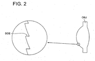
- blaze-formed diffractive structure DOE On a plane of incidence of the light-converging optical element OBJ, there is formed blaze-formed diffractive structure DOE shown in Fig. 2 .
- the blaze-formed diffractive structure DOE is provided for the purpose of correcting chromatic aberration that is owned by light-converging optical element OBJ itself for the light flux emitted from the first light source, and it is designed specifically so that an absolute value of the chromatic aberration may be 0.15 ⁇ m/nm or less.
- First correcting element L1 has a collimating function to convert the first light flux emitted from the first light source LD1 as a divergent light into a collimated light, and on its plane of emergence, there is formed blaze-formed diffractive structure DOE that is the same as one shown in Fig. 2 .
- the blaze-formed diffractive structure DOE is provided for the purpose of correcting chromatic aberration that is owned by the first correcting element L1 itself for the light flux emitted from the first light source, and it is designed specifically so that an absolute value of the chromatic aberration may be 2.1 ⁇ m/nm or less.
- First correcting element L2 has a collimating function to convert the second light flux emitted from the second light source LD2, and has a function to change a divergent angle of the third light flux emitted from the third light source LD3 as a. divergent light to be a smaller divergent angle, and on each of its plane of incidence and plane of emergence, there is formed blaze-formed diffractive structure DOE that is the same as one shown in Fig. 2 .
- Fig. 3 (a) is a diagram showing the values of chromatic aberration owned by the light-converging optical element itself for the first light flux and the second light flux, in which the value of chromatic aberration owned by the light-converging optical element itself for the first light flux is shown with a circle, while, the value of chromatic aberration owned by the light-converging optical element itself for the second light flux is shown with a square.
- Fig. 3 (a) shows that an absolute value of chromatic aberration owned by the light-converging optical element itself for the first light flux is made to be 0.15 ⁇ m/nm or less, namely, to be zero substantially, by the blaze-formed diffractive structure DOE formed on the light-converging optical element, as stated above.
- an absolute value of the chromatic aberration owned by the first correcting element itself for the first light flux is also made to be 2.1 ⁇ m/nm or less, namely, to be zero substantially, by the blaze-formed diffractive structure DOE formed on the first correcting element.
- chromatic aberration of the light-converging optical element itself for the first light source and chromatic aberration of the first correcting element itself are substantially zero respectively, it is possible to control chromatic aberration of the first light-converging spot in the case of using an optical pickup device to be within a range that is necessary for reproducing and/or recording of information.
- the blaze-formed diffractive structure DOE of the light-converging optical element is designed so that the chromatic aberration of the light-converging optical element itself for the first light flux may be substantially zero, the chromatic aberration of the light-converging optical element for the second light flux remains and a value of the chromatic aberration becomes negative specifically, as shown in Fig. 3 (a) .
- the blaze-formed diffractive structure DOE on each of the plane of incidence and the plane of emergence of the second correcting element is designed so that a value of chromatic aberration owned by the second correcting element itself for the second light flux may be positive, although an illustration thereof is omitted.
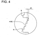
- a diffractive structure formed on each of light-converging optical element OBJ, first correcting element L1 and second correcting element L2 may also be superimposed-type diffractive structure HOE representing a structure wherein there are arranged plural ring-shaped zones R in each of which a staircase structure is formed as shown in Fig. 4 in a way that their centers are on the optical axis.
- a light flux with wavelength ⁇ 2 is made to be a diffracted light diffracted in the first-order direction by the superimposed-type diffractive structure HOE.
- the diffraction efficiency of the first-order diffracted light for the laser light flux with wavelength ⁇ 2 in this case is 87.5% which is a sufficient amount of light for recording/reproducing of information for DVD.
- the present embodiment it is not necessary to utilize the aforesaid wavelength selectivity of superimposed-type diffractive structure HOE, because only the first light flux passes through the first correcting element L1.
- the first correcting element L1 for example, is arranged between the second beam splitter BS2 and light-converging optical element OBJ, the first - third light fluxes pass through the first correcting element L1.
- the first correcting element L1, the second correcting element L2 and optical pickup device PU1 shown in the present embodiment make it possible to prevent increase of wavefront aberration by controlling chromatic aberration of a light-converging optical element itself and of the first correcting element itself to be zero substantially, even when wavelength fluctuations are caused in the case of tracking in reproducing and/or recording for HD-DVD.
- a diffractive structure is provided on each of first correcting element L1, second correcting element L2 and objective lens OBJ.
- Fig. 3 (b) is a diagram showing the values of chromatic aberration owned by the light-converging optical element itself for the first light flux and the second light flux, in which the value of chromatic aberration owned by the light-converging optical element itself for the first light flux is shown with a circle, while, the value of chromatic aberration owned by the light-converging optical element itself for the second light flux is shown with a square.
- an absolute value of chromatic aberration owned by the light-converging optical element itself for the second light flux is made to be 0.25 ⁇ m/nm or less, namely, to be zero substantially, by the blaze-formed diffractive structure DOE formed on the light-converging optical element OBJ, as stated above.
- an absolute value of chromatic aberration owned by the second light-converging optical element itself for the second light flux is made to be 3.5 ⁇ m/nm or less, namely, to be zero substantially, by the blaze-formed diffractive structure DOE formed on the second correcting element L2, as stated above.
- the blaze-formed diffractive structure DOE of the light-converging optical element OBJ is designed so that the chromatic aberration of the light-converging optical element itself for the second light flux may be substantially zero, the chromatic aberration of the light-converging optical element itself for the first light flux remains and a value of the chromatic aberration becomes positive specifically, as shown in Fig. 3 (b) .
- the blaze-formed diffractive structure DOE of the first correcting element L1 is designed so that a value of chromatic aberration owned by the first correcting element itself for the first light flux may be negative, although an illustration thereof is omitted.
- the first correcting element L1, the second correcting element L2 and optical pickup device PU2 shown in the present embodiment make it possible to prevent a change for the worse of wavefront aberration by controlling chromatic aberration of a light-converging optical element itself and of the first correcting element itself for the first light flux to be zero substantially, even when wavelength fluctuations are caused in the case of tracking in reproducing and/or recording for DVD.
- a demand for chromatic aberration correction is low, compared with HD-DVD, therefore, it is possible to control chromatic aberration of the second light-converging spot to be within a range necessary for reproducing and/or recording of information, even in the case of an arrangement where a diffractive structure is not provided on the second correcting element L2, and the second correcting element itself has chromatic aberration for the second light flux.
- a sufficient amount of light can be secured, because a loss of an amount of light in the occasion for the second light flux to pass through the diffractive ring-shaped zones is not caused.
- optical pickup device PU3 of the present embodiment a diffractive structure is provided on each of first correcting element L1, second correcting element L2 and objective lens OBJ.
- Fig. 3 (c) is a diagram showing the values of chromatic aberration owned by the light-converging optical element itself for the first light flux and the second light flux, in which the value of chromatic aberration owned by the light-converging optical element itself for the first light flux is shown with a circle, while, the value of chromatic aberration owned by the light-converging optical element itself for the second light flux is shown with a square.
- a value of chromatic aberration owned by the light-converging optical element itself for the first light flux is positive.
- the blaze-formed diffractive structure DOE of the first correcting element L1 is designed so that a value of chromatic aberration owned by the first correcting element itself for the first light flux may be negative, although an illustration thereof is omitted.
- a value of chromatic aberration owned by the light-converging optical element itself for the second light flux is positive.
- the blaze-formed diffractive structure DOE of the second correcting element L2 is designed so that a value of chromatic aberration owned by the second correcting element itself for the second light flux may be negative, although an illustration thereof is omitted.
- the first correcting element L1, the second correcting element L2 and optical pickup device PU3 shown in the present embodiment make it possible to make values of chromatic aberration owned by the light-converging optical element itself for the first and second light fluxes to be of the same signs (positive), and thereby to weaken diffractive effects of the blaze-formed diffractive structure DOE formed on light-converging optical element OBJ. Therefore, an improvement of processability and reduction of a loss of an amount of light can be attained by expanding a pitch of diffraction.
- a diffractive structure is provided on each of first correcting element L1, second correcting element L2 and objective lens OBJ.
- Fig. 3 (d) is a diagram showing the values of chromatic aberration owned by the light-converging optical element itself for the first light flux and the second light flux, in which the value of chromatic aberration owned by the light-converging optical element itself for the first light flux is shown with a circle, while, the value of chromatic aberration owned by the light-converging optical element itself for the second light flux is shown with a square.
- a value of chromatic aberration owned by the light-converging optical element itself for the first light flux is negative.
- the blaze-formed diffractive structure DOE of the first correcting element L1 is designed so that a value of chromatic aberration owned by the first correcting element itself for the first light flux may be positive, although an illustration thereof is omitted.
- a value of chromatic aberration owned by the light-converging optical element itself for the second light flux is negative.
- the blaze-formed diffractive structure DOE of the second correcting element L2 is designed so that a value of chromatic aberration owned by the second correcting element itself for the second light flux may be positive, although an illustration thereof is omitted.
- a demand for chromatic aberration correction is low, compared with HD-DVD, therefore, it is possible to control chromatic aberration of the second light-converging spot to be within a range necessary for reproducing and/or recording of information, even in the case of an arrangement where a diffractive structure is not provided on the second correcting element L2, and the second correcting element itself has chromatic aberration for the second light flux.
- a sufficient amount of light can be secured, because a loss of an amount of light in the occasion for the second light flux to pass through the diffractive ring-shaped zones is not caused.
- optical pickup device PU5 of the present embodiment a diffractive structure is provided on each of second correcting element L2 and objective lens OBJ.
- Fig. 3 (e) is a diagram showing the values of chromatic aberration owned by the light-converging optical element itself for the first light flux and the second light flux, in which the value of chromatic aberration owned by the light-converging optical element itself for the first light flux is shown with a circle, while, the value of chromatic aberration owned by the light-converging optical element itself for the second light flux is shown with a square.
- a value of chromatic aberration owned by the light-converging optical element itself for the first light flux is positive, and this positive chromatic aberration is canceled by a value (negative) of chromatic aberration owned by the first correcting element itself for the first light flux in the structure, though an illustration thereof is omitted.
- a value of chromatic aberration owned by the light-converging optical element itself for the second light flux is negative.
- the blaze-formed diffractive structure DOE of the second correcting element L2 is designed so that a value of chromatic aberration owned by the second correcting element itself for the second light flux may be positive, although an illustration thereof is omitted.
- a loss in an amount of light in the case for the first light flux to pass through the first correcting element is not caused, and processability can be improved.
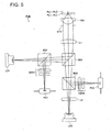
- Fig. 5 is a diagram showing schematically the structure of optical pickup device PU6 capable of conducting recording/reproducing of information properly for any one of HD-DVD (first optical information recording medium) and DVD (second optical information recording medium).
- the structure which is the same as that in the aforesaid First Embodiment is given the same symbol and an explanation thereof will be omitted.
- Optical pickup device PU6 is composed of violet semiconductor laser LD1 (first light source) that emits a laser light flux (first light flux) with wavelength 407 nm that is emitted when conducting recording/reproducing of information for HD-DVD, photodetector PD1 for the first light flux, red semiconductor laser LD2 (second light source) that emits a laser light flux (second light flux) with wavelength 655 nm that is emitted when conducting recording/reproducing of information for DVD, photodetector PD2 for the second light flux, first correcting element L1 through which the first and second light fluxes pass, second correcting element L2 through which only the second light flux passes, objective lens (light-converging optical element) OBJ having a function to converge each laser light flux on each of information recording surfaces RL1 and RL2, first beam splitter BS1, second beam splitter BS2, third beam splitter BS3, diaphragm STO, and sensor lenses SEN1 and SEN2.
- violet semiconductor laser LD1
- a diffractive structure is provided on each of the first correcting element L1, the second correcting element L2 and objective lens OBJ, for which the detailed explanation will be given later.
- violet semiconductor laser LD1 When conducting recording/reproducing of information for HD-DVD in optical pickup device PU6, violet semiconductor laser LD1 is first driven to emit light as shown in Fig. 5 where a light path is indicated. A divergent light flux emitted from the violet semiconductor laser LD1 passes through the first beam splitter BS1, then, is reflected on the second beam splitter BS2 and is transmitted through the first correcting element L1 to be converted into a collimated light flux, and arrives at light-converging optical element OBJ.
- n1 th diffracted light (n1 is a natural number) of the first light flux generated by diffractive effects of the diffractive structure of the light-converging optical element OBJ is converged on information recording surface RL1 through protective layer PL1 of HD-DVD to form a spot (first light-converging spot).
- This first light-converging spot is controlled to be within a range necessary for reproducing and/or recording of information in terms of chromatic aberration, and an absolute value of chromatic aberration for the first light-converging spot is controlled specifically to be 0.15 ⁇ m/nm or less.
- the light-converging optical element OBJ conducts focusing and tracking with biaxial actuator AC (not shown) that is arranged on the periphery of the light-converging optical element OBJ.
- a reflected light flux modulated by information pits on information recording surface RL1 passes again through the light-converging optical element OBJ and the first correcting element L1, and is reflected on the second beam splitter BS2, then is branched by the first beam splitter BS1, and is given astigmatism by sensor lens SEN 1 to be converged on a light-receiving surface of photodetector PD 1.
- sensor lens SEN 1 to be converged on a light-receiving surface of photodetector PD 1.
- the red semiconductor laser LD2 When conducting recording/reproducing of information for DVD, the red semiconductor laser LD2 is first driven to emit light as shown in Fig. 5 where a light path is indicated. A divergent light flux emitted from the red semiconductor laser LD2 passes through the second correcting element L2, the third beam splitter BS3 and the second beam splitter BS2, and then, is converted into a collimated light flux after being transmitted through the first correcting element L1, to arrive at light-converging optical element OBJ.
- n2 th diffracted light (n2 is a natural number satisfying n1 ⁇ n2) of the second light flux generated by diffractive effects of the diffractive structure of light-converging optical element OBJ is converged on information recording surface RL2 through protective layer PL2 of DVD to form a spot (second light-converging spot).
- This second light-converging spot is controlled, in terms of chromatic aberration, to be within a range necessary for reproducing and/or recording of information, and an absolute value of chromatic aberration of the second light-converging spot is specifically controlled to be 0.25 ⁇ m/nm or less.
- the light-converging optical element OBJ conducts focusing and tracking with biaxial actuator AC that is arranged on the periphery of the light-converging optical element OBJ.
- a reflected light flux modulated by information pits on information recording surface RL2 passes again through the light-converging optical element OBJ, the first correcting element L1, the second beam splitter BS2 to be branched by the third beam splitter BS3, and is given astigmatism by sensor lens SEN 2, and is converged on the light-receiving surface of photodetector PD 2.
- information recorded on DVD can be read by the use of output signals of photodetector 2.
- the light-converging optical element OBJ is a plastic single lens with aspheric surfaces on its both sides having a function to make the first and second light fluxes to be converged respectively on information recording surfaces RL1 and RL2.
- the light-converging optical element may also be constructed by combining a plurality of optical elements.
- blaze-formed diffractive structure DOE On a plane of incidence of the light-converging optical element OBJ, there is formed blaze-formed diffractive structure DOE shown in Fig. 2 .
- the blaze-formed diffractive structure DOE is provided for the purpose of correcting chromatic aberration that is owned by light-converging optical element OBJ itself for the light flux emitted from the second light source, and it is designed specifically so that an absolute value of the chromatic aberration may be 0.25 ⁇ m/nm or less.
- the first correcting element L1 has a collimating function to make the first light flux emitted from the first light source LD1 as a divergent light and the second light flux emitted from the second light source LD2 as a divergent light to emerge as collimated light, and on a plane of emergence of the first correcting element L1, there is formed blaze-formed diffractive structure DOE that is the same as one shown in Fig. 2 .
- blaze-formed diffractive structure DOE On a plane of emergence of the second correcting element L2, there is formed blaze-formed diffractive structure DOE that is the same as one shown in Fig. 2 .
- Fig. 3 (b) is a diagram showing the values of chromatic aberration owned by the light-converging optical element itself for the first light flux and the second light flux, in which the value of chromatic aberration owned by the light-converging optical element itself for the first light flux is shown with a circle, while, the value of chromatic aberration owned by the light-converging optical element itself for the second light flux is shown with a square.
- an absolute value of chromatic aberration owned by the light-converging optical element itself for the second light flux is made to be 0.25 ⁇ m/nm or less, namely, to be zero substantially, by the blaze-formed diffractive structure DOE formed on the light-converging optical element OBJ, as stated above.
- the blaze-formed diffractive structure DOE of the light-converging optical element OBJ is designed so that the chromatic aberration of the light-converging optical element itself for the second light flux may be substantially zero, the chromatic aberration of the light-converging optical element for the first light flux remains and a value of the chromatic aberration becomes positive specifically, as shown in Fig. 3 (b) .
- the blaze-formed diffractive structure DOE of the first correcting element L1 is designed so that a value of chromatic aberration owned by the first correcting element itself for the first light flux may be negative, although an illustration thereof is omitted.
- the blaze-formed diffractive structure DOE of the first correcting element L1 is designed so that a value of the chromatic aberration owned by the first correcting element itself for the first light flux may be negative, the chromatic aberration of the first correcting element itself remains even for the second light flux, and a value of the chromatic aberration becomes negative specifically.
- the blaze-formed diffractive structure DOE of the second correcting element L2 is designed so that a value of chromatic aberration owned by the second correcting element itself for the second light flux may be positive, although an illustration thereof is omitted.
- a diffractive structure is provided on each of the first correcting element L1, the second correcting element L2 and objective lens OBJ.
- blaze-formed diffractive structure DOE On the plane of incidence of light-converging optical element OBJ, there is formed blaze-formed diffractive structure DOE as shown in Fig. 2 .
- the blaze-formed diffractive structure DOE is provided for the purpose of correcting chromatic aberration that is owned by light-converging optical element OBJ itself for the light flux emitted from the first light source, and it is designed specifically so that an absolute value of chromatic aberration may be 0.15 ⁇ m/nm or less.
- Fig. 3 (a) is a diagram showing the values of chromatic aberration owned by the light-converging optical element itself for the first light flux and the second light flux, in which the value of chromatic aberration owned by the light-converging optical element itself for the first light flux is shown with a circle, while, the value of chromatic aberration owned by the light-converging optical element itself for the second light flux is shown with a square.
- an absolute value of chromatic aberration owned by the light-converging optical element itself for the first light flux is made by the blaze-formed diffractive structure DOE formed on the light-converging optical element to be 0.15 ⁇ m/nm or less, namely, to be zero substantially, as stated above.
- an absolute value of the chromatic aberration owned by the first correcting element itself for the first light flux is also made by the blaze-formed diffractive structure DOE formed on the first correcting element to be 2.1 ⁇ m/nm or less, namely, to be zero substantially, as stated above, though an illustration thereof will be omitted here.
- chromatic aberration of the light-converging optical system itself for the first light flux and chromatic aberration of the first correcting element itself to be zero substantially, it is possible to control chromatic aberration of the first light-converging spot in the case of using an optical pickup device to be within a range that is necessary for reproducing and/or recording of information.
- the blaze-formed diffractive structure DOE of the light-converging optical element is designed so that the chromatic aberration of the light-converging optical element itself for the first light flux may be substantially zero, the chromatic aberration of the light-converging optical element for the second light flux remains and a value of the chromatic aberration becomes negative specifically, as shown in Fig. 3 (a) .
- the blaze-formed diffractive structure DOE of the first correcting element L1 is designed so that a value of the chromatic aberration owned by the first correcting element itself for the first light flux may be zero substantially, the chromatic aberration of the first correcting element itself remains for the second light flux, and a value of the chromatic aberration becomes negative specifically.
- the blaze-formed diffractive structure DOE of the second correcting element L2 is designed so that a value of chromatic aberration owned by the second correcting element itself for the second light flux may be positive, although an illustration thereof is omitted.
- the present example is one relating to an optical pickup device wherein it is possible to control chromatic aberration of the first light-converging spot in the case of using an optical pickup device to be within a range that is necessary for reproducing and/or recording of information, by making the negative chromatic aberration of the light-converging optical element itself for the first light flux to be cancelled with positive chromatic aberration of the first correcting element itself, like the Fourth Embodiment stated above, and it is possible to control chromatic aberration of the second light-converging spot in the case of using an optical pickup device to be within a range that is necessary for reproducing and/or recording of information, by making negative chromatic aberration of the light-converging optical element itself for the second light flux to be cancelled by positive chromatic aberration of the second correcting element itself.
- Lens data of respective optical elements are shown in Table 1 and Table 2.
- Table 2 Aspheric surface data First correcting element Third surface Aspheric surface coefficient ⁇ -6.6436 x E+1 Fourth surface (HD-DVD: First-order Blazed wavelength 1 mm) Aspheric surface coefficient ⁇ -8.3465 x E-1 Optical path difference function C2 -6.2961 x E-0 C4 -1.5298 x E-2 Second correcting element Third surface (DVD: Second-order, CD: First-order Blazed wavelength 1 mm) Aspheric surface coefficient ⁇ -1.0000 x E+3 Optical path difference function C2 +2.4248 x E+0 C4 +6.2330 x E-4 Fourth surface (DVD: First-order, CD: First-order Blazed wavelength 1 mm) Aspheric surface coefficient ⁇ -4.7604 x E-1 Optical path difference function C2 +2.0944 x E+1 C4 +1.2308 x E-1 Objective lens Sixth surface
- a blaze-formed diffractive structure is formed on a plane of emergence (fourth surface) of the first correcting element, a plane of incidence (third surface) and a plane of emergence (fourth surface) both of the second correcting element, and on a plane of incidence (sixth surface) of a light-converging optical element (objective lens).
- magnifications m1 and m2 of the objective lens for the first light flux and the second light flux are zero substantially, the first light flux and the second light flux enter the objective lens as parallel rays, magnification m3 for the third light flux is negative, and the third light flux enters the objective lens as divergent rays.
- X (h) represents an axis in the optical axis direction (advancing direction of light is positive)
- ⁇ represents a conic constant
- a 2i represents a coefficient of aspheric surface.
- a pitch of the diffractive ring-shaped zones is stipulated by the expression wherein a coefficient shown in Table 2 is substituted in the optical path difference function of Numeral 2.
- B 2i represents a coefficient of the optical path difference function
- ⁇ represents a working wavelength
- the present example is one relating to an optical pickup device wherein it is possible to control chromatic aberration of the first light-converging spot in the case of using an optical pickup device to be within a range that is necessary for reproducing and/or recording of information, by making the chromatic aberration of the light-converging optical element for the first light source itself and the chromatic aberration of the first correcting element itself to be zero substantially, like the First Embodiment, and it is possible to control chromatic aberration of the second light-converging spot in the case of using an optical pickup device to be within a range that is necessary for reproducing and/or recording of information, by making negative chromatic aberration of the light-converging optical element itself for the second light flux to be cancelled by positive chromatic aberration of the second correcting element itself.
- Lens data of respective optical elements are shown in Table 3 and Table 4.
- Table 4 Aspheric surface data
- First correcting element Third surface Aspheric surface coefficient ⁇ -2.9816 x E+0 Fourth surface (HD-DVD: First-order Blazed wavelength 1 mm)
- Second correcting element Third surface Aspheric surface coefficient ⁇ -6.8225 x E-0 Fourth surface (DVD: First-order, CD: First-order Blazed wavelength 1 mm)
- Sixth surface AOD: Third-order, DVD: Second-order, CD: Second-order Blazed
- a blaze-formed diffractive structure is formed on a plane of emergence (fourth surface) of the first correcting element, a plane of emergence (fourth surface) of the second correcting element and a plane of incidence (sixth surface) of the light-converging optical element.
- magnifications m1 and m2 of the objective lens for the first light flux and the second light flux are zero substantially, the first light flux and the second light flux enter the objective lens as parallel rays, magnification m3 for the third light flux is negative, and the third light flux enters the objective lens as divergent rays.
- a pitch of the diffractive ring-shaped zones is stipulated by the expression wherein a coefficient shown in Table 4 is.substituted in the optical path difference function of the Numeral 2.
- the present example is one relating to an optical pickup device wherein it is possible to control chromatic aberration of the second light-converging spot in the case of using an optical pickup device to be within a range that is necessary for reproducing and/or recording of information, by making the chromatic aberration of the light-converging optical element for the second light flux itself and the chromatic aberration of the second correcting element itself to be zero substantially, like the aforesaid Second Embodiment, and it is possible to control chromatic aberration of the first light-converging spot in the case of using an optical pickup device to be within a range that is necessary for reproducing and/or recording of information, by making negative chromatic aberration of the light-converging optical element itself for the first light flux to be cancelled by positive chromatic aberration of the first correcting element itself.
- Lens data of respective optical elements are shown in Table 5 and Table 6.
- Table 6 Aspheric surface data
- First correcting element Third surface Aspheric surface coefficient ⁇ -1.2865 x E-1 Fourth surface
- Optical path difference function C2 -3.4973 x E+1 C4 -3.1167 x E-1
- Second correcting element Third surface Aspheric surface coefficient ⁇ +5.0000 x E-0 Fourth surface (DVD: Second-order, CD: First-order Blazed wavelength 1 mm)
- Sixth surface AOD: Third-order, DVD: Second-order, CD: Second-order Blazed wavelength 1 mm
- a blaze-formed diffractive structure is formed on a plane of emergence (fourth surface) of the first correcting element, a plane of emergence (fourth surface) of the second correcting element and a plane of incidence (sixth surface) of the light-converging optical element.
- magnifications m1 and m2 of the objective lens for the first light flux and the second light flux are zero substantially, the first light flux and the second light flux enter the objective lens as parallel rays, magnification m3 for the third light flux is negative, and the third light flux enters the objective lens as divergent rays.
- a pitch of the diffractive ring-shaped zones is stipulated by the expression wherein a coefficient shown in Table 6 is substituted in the optical path difference function of the Numeral 2.
- the present example is one relating to an optical pickup device wherein it is possible to control chromatic aberration of the second light-converging spot in the case of using an optical pickup device to be within a range that is necessary for reproducing and/or recording of information, by making the negative chromatic aberration of the first correcting element for the second light flux by the positive chromatic aberration of the second correcting element itself, and it is possible to control chromatic aberration of the first light-converging spot in the case of using an optical pickup device to be within a range that is necessary for reproducing and/or recording of information, by making positive chromatic aberration of the light-converging optical element itself for the first light flux to be cancelled by negative chromatic aberration of the first correcting element itself.
- Lens data of respective optical elements are shown in Table 7 and Table 8. (Table 8) Correcting element for DVD Second surface Optical path difference function (DVD: First-order Blazed wavelength 661 nm) C2 2.6331E-02 C4 1.2847E-04 Collimator to be used commonly for HD-DVD/DVD Sixth surface (HD-DVD: Fifth-order, DVD: Third-order Blazed wavelength 407.9 nm) Aspheric surface coefficient ⁇ -1.0000E-01 A1 -9.6629E-06 A2 -2.5101E-08 Optical path difference function C2 -2.4248 x E+0 Objective lens Eighth surface (1.015mm ⁇ h) Aspheric surface coefficient ⁇ -5.7409E-01 A1 7.1066E-04 A2 -2.4404E-03 A3 1.1090E-03 A4 -1.9304E-04 A5 1.4092E-05 A6 -7.7600E-07 Optical path difference function (DVD: First-order Blazed wavelength 661
- a blaze-formed diffractive structure is formed on each of a plane of emergence (sixth surface) of the first correcting element, a plane of emergence (second surface) of the second correcting element and on a plane of incidence (eighth surface, 8' th surface) of the light-converging optical element (objective lens).
- magnifications m1 and m2 of the objective lens for the first light flux and the second light flux are zero substantially, and the first light flux and the second light flux enter the objective lens as parallel rays.
- a pitch of the diffractive ring-shaped zones is stipulated by the expression wherein a coefficient shown in Table 8 is substituted in the optical path difference function of the Numeral 2.
- the present example is one relating to an optical pickup device wherein it is possible to control chromatic aberration of the first light-converging spot in the case of using an optical pickup device to be within a range that is necessary for reproducing and/or recording of information, by making the chromatic aberration of the light-converging optical element itself for the first light flux and chromatic aberration of the first correcting element itself to be zero substantially, and it is possible to control chromatic aberration of the second light-converging spot in the case of using an optical pickup device to be within a range that is necessary for reproducing and/or recording of information, by making negative chromatic aberration of the light-converging optical element itself for the second light flux and negative chromatic aberration of the first correcting element itself to be cancelled by positive chromatic aberration of the second correcting element itself.
- Lens data of respective optical elements are shown in Table 9 and Table 10.
- Table 10 Aspheric surface data Correcting element for DVD Second surface Optical path difference function (DVD: First-order Blazed wavelength 655 nm) C2 2.2008E-02 C4 1.0027E-04 Collimator to be used commonly for HD-DVD/DVD Sixth surface Aspheric surface coefficient ⁇ -1.0000E-01 A1 2.4710E-05 A2 1.1294E-07
- Optical path difference function (HD-DVD: Second-order, DVD: First-order Blazed wavelength 407 nm) C2 -1.1527E-03 Objective lens Eighth surface Aspheric surface coefficient ⁇ -4.4715E-01 A1 -7.2396E-04 A2 -1.3187E-03 A3 5.4370E-04 A4 -1.0983E-04 A5 8.5286E-06 A6 -1.3509E-06
- Optical path difference function (HD DVD: Third-order, DVD:Second-
- a blaze-formed diffractive structure is formed on each of a plane of emergence (sixth surface) of the first correcting element, a plane of emergence (second surface) of the second correcting element and on a plane of incidence (eighth surface) of the light-converging optical element (objective lens).
- magnifications m1 and m2 of the objective lens for the first light flux and the second light flux are zero substantially, and the first light flux and the second light flux enter the objective lens as parallel rays.
- an aspheric surface that is stipulated by the expression wherein the coefficients shown in Tables 9 and 10 are substituted in the aforesaid Numeral 1, and is axially symmetric around optical axis L.
- a pitch of the diffractive ring-shaped zones is stipulated by the expression wherein a coefficient shown in Table 10 is substituted in the optical path difference function of the Numeral 2.
- Table 11 shows chromatic aberration (abbreviated as HD-DVD) for the first light flux in the combination of the objective lens and the first correcting element and chromatic aberration (abbreviated as DVD) for the second light flux in the combination of the objective lens and the second correcting element, in Examples 1 - 3.
- Chromatic aberration ( ⁇ m/nm) in the case of combination of objective lens and correcting element HD DVD DVD Example 1 0.04 -0.02
- Example 2 0.04 -0.01
- Table 12 shows chromatic aberration (abbreviated as HD-DVD) for the first light flux in the combination of the objective lens and the first correcting element and chromatic aberration (abbreviated as DVD) for the second light flux in the combination of the objective lens, the first correcting element and the second correcting element, in Examples 4 and 5.
- (Table 12) Chromatic aberration ( ⁇ m/nm) in the case of combination of objective lens and correcting element HD DVD DVD Example 4 0 0.02
- Example 5 0.1 -0.08
- HD-DVD has been exemplified as a high density optical disc.
- the high density optical disc is not limited to HD-DVD, in the invention.
Landscapes
- Physics & Mathematics (AREA)
- Optics & Photonics (AREA)
- Optical Head (AREA)
- Lenses (AREA)
Claims (2)
- Optische Bildaufnahmevorrichtung miteiner ersten Lichtquelle (LD1), die ausgestaltet ist, um einen Lichtfluss mit einer Wellenlänge λ1 zu emittieren;einer zweiten Lichtquelle (LD2), die ausgestaltet ist, um einen Lichtfluss mit einer Wellenlänge λ2 zu emittieren, der die Bedingung erfüllt: 600 nm ≤ λ2 ≤ 700 nm;einem lichtkonvergierenden optischen Element (OBJ) mit einer Beugungsstruktur und so ausgestaltet, dass ermöglicht wird, dass der Lichtfluss mit der Wellenlänge λ1 und der Lichtfluss mit der Wellenlänge λ2 durchtreten;einem ersten Korrekturelement (L1) mit einer Beugungsstruktur und so ausgestaltet, dass zumindest der Lichtfluss mit der Wellenlänge λ1 durchtreten kann; undeinem Strahlteiler (BS1), um einen optischen Weg für den Lichtfluss der Wellenlänge λ1 und jenen für den Lichtfluss mit der Wellenlänge λ2 dazu zu bringen, miteinander hinsichtlich ihren Position überein zu stimmen wobeidie optische Bildaufnahmevorrichtung (PU1) ausgestaltet ist, so dass das Wiedergeben und/oder das Aufzeichnen von Information auf einem zweiten optischen Informationsaufzeichnungsmedium (DVD) mit dem Lichtfluss mit der Wellenlänge λ2 durchgeführt wird, mit einer Schutzsubstratdicke t2, die die Bedingung 0,5 mm ≤ t2 ≤ 0,7 mm erfüllt, dadurch gekennzeichnet, dass:die optische Bildaufnahmevorrichtung so ausgestaltet ist, dass das Wiedergeben und/oder das Aufzeichnen von Information auf einem ersten optischen Informationsaufzeichnungsmedium (HD-DVD) mit dem Lichtfluss mit der Wellenlänge λ1 durchgeführt wird, mit einer Schutzsubstratdicke t1, die die folgende Bedingung: 0 mm < t1 ≤ 0,7 mm erfüllt;wobei λ1 die Bedingung 380 nm ≤ λ1 ≤ 450 nm erfüllt;
wobei die optische Bildaufnahmevorrichtung des Weiteren ein zweites Korrekturelement (L2) enthält, das ausgestaltet ist, so dass zumindest der Lichtfluss mit der Wellenlänge λ2 hindurchtreten kann;
wobei zumindest eines von dem ersten Korrekturelement (L1) und dem zweiten Korrekturelement (L2) zwischen dem Strahlteiler (BS1) und der ersten Lichtquelle (LD1) oder zwischen dem Strahlteiler (BS1) und der zweiten Lichtquelle (LD2) angeordnet ist; und
wobei die optische Bildaufnahmevorrichtung (PU1) ist so ausgestaltet, dass ein erster konvergierter Lichtpunkt, der auf dem ersten optischen Informationsaufzeichnungsmedium (HD-DVD) durch das gebeugte Licht n1ter Ordnung, wobei n1 eine ganze Zahl ist, des Lichtflusses der Wellenlänge λ1 gebildet wird, der durch den Beugungseffekt des lichtkonvergierenden optischen Elements (OBJ) erzeugt wird, und ein zweiter konvergierter Lichtpunkt, der auf dem zweiten optischen Informationsaufzeichnungsmedium (DVD) durch das gebeugte Licht n2ter Ordnung, wobei n2 eine natürliche Zahl ist, die die Bedingung erfüllt: n1 ≠ n2, des Lichtflusses mit der Wellenlänge λ2 gebildet wird, der durch die Beugungseffekte des lichtkonvergierenden optischen Elements (OPJ) erzeugt wird, so gesteuert sind, dass sie in einem Bereich sind, der für das Wiedergeben und/oder das Aufzeichnen von Information bezüglich der chromatischen Aberration notwendig ist, durch Ausgestalten des ersten Korrekturelements (L1):um eine positive chromatische Aberration für den Lichtfluss mit der Wellenlänge λ1 zu haben, wenn die chromatische Aberration des lichtkonvergierenden optischen Elements (OBJ) für den Lichtfluss mit der Wellenlänge λ1 negativ ist, um so die chromatische Aberration des lichtkonvergierenden optischen Elements (OBJ) zu korrigieren,um eine negative chromatische Aberration für den Lichtfluss mit der Wellenlänge λ1 zu haben, wenn die chromatische Aberration des lichtkonvergierenden optischen Elements (OBJ) für den Lichtfluss mit der Wellenlänge λ1 positiv ist, um so die chromatische Aberration für das lichtkonvergierende optische Element (OBJ) zu korrigieren, undum im Wesentlichen keine chromatische Aberration für den Lichtfluss mit der Wellenlänge λ1 zu haben, wenn die chromatische Aberration für das lichtkonvergierende optische Element (OBJ) im Wesentlichen 0 für den Lichtfluss der Wellenlänge λ1 ist, unddurch Ausgestalten des zweiten Korrekturelement (L2),um eine positive chromatische Aberration für den Lichtfluss mit der Wellenlänge λ2 zu haben, wenn die chromatische Aberration des lichtkonvergierenden optischen Elements (OBJ) für den Lichtfluss mit der Wellenlänge λ2 negativ ist, um so die chromatische Aberration des lichtkonvergierenden optischen Elements (OBJ) zu korrigieren,um eine negative chromatische Aberration für den Lichtfluss mit der Wellenlänge λ2 zu haben, wenn die chromatische Aberration des lichtkonvergierenden optischen Elements (OBJ) für den Lichtfluss mit der Wellenlänge λ2 positiv ist, um so die chromatische Aberration des lichtkonvergierenden optischen Elements (OBJ) zu korrigieren, undum im Wesentlichen keine chromatische Aberration für den Lichtfluss mit der Wellenlänge λ2 zu haben, wenn die chromatische Aberration des lichtkonvergierenden optischen Elements (OBJ) im Wesentlichen 0 für den Lichtfluss mit der Wellenlänge λ2 ist. - Optische Bildaufnahmevorrichtung nach Anspruch 1, bei der das zweite Korrekturelement (L2) mit einer Beugungsstruktur versehen ist.
Applications Claiming Priority (2)
| Application Number | Priority Date | Filing Date | Title |
|---|---|---|---|
| JP2003374616 | 2003-11-04 | ||
| JP2003374616 | 2003-11-04 |
Publications (3)
| Publication Number | Publication Date |
|---|---|
| EP1530207A2 EP1530207A2 (de) | 2005-05-11 |
| EP1530207A3 EP1530207A3 (de) | 2007-10-10 |
| EP1530207B1 true EP1530207B1 (de) | 2010-03-17 |
Family
ID=34431260
Family Applications (1)
| Application Number | Title | Priority Date | Filing Date |
|---|---|---|---|
| EP04256727A Expired - Lifetime EP1530207B1 (de) | 2003-11-04 | 2004-11-01 | Optische Abtastvorrichtung mit Korrekturelement |
Country Status (8)
| Country | Link |
|---|---|
| US (1) | US7304935B2 (de) |
| EP (1) | EP1530207B1 (de) |
| JP (1) | JP4730099B2 (de) |
| KR (1) | KR20060115863A (de) |
| CN (1) | CN100527239C (de) |
| DE (1) | DE602004026021D1 (de) |
| TW (1) | TW200526979A (de) |
| WO (1) | WO2005043522A1 (de) |
Families Citing this family (2)
| Publication number | Priority date | Publication date | Assignee | Title |
|---|---|---|---|---|
| JP4339182B2 (ja) * | 2004-05-28 | 2009-10-07 | 株式会社リコー | 光ピックアップとこれを用いた光情報処理装置 |
| EP2963475A4 (de) * | 2013-02-28 | 2016-10-26 | Olympus Corp | Probenbeobachtungsverfahren und probenbeobachtungsvorrichtung |
Family Cites Families (14)
| Publication number | Priority date | Publication date | Assignee | Title |
|---|---|---|---|---|
| US6556533B1 (en) * | 1996-10-01 | 2003-04-29 | Matsushita Electric Industrial Co., Ltd. | Optical pickup device |
| JP2000090477A (ja) * | 1998-09-09 | 2000-03-31 | Pioneer Electronic Corp | 光ピックアップ、情報再生装置及び情報記録装置 |
| JP3976457B2 (ja) * | 1998-10-28 | 2007-09-19 | 松下電器産業株式会社 | 光学ヘッド |
| TW479253B (en) * | 1998-12-17 | 2002-03-11 | Konishiroku Photo Ind | Objective lens for correcting chromatic aberration for use in recording toor reproducing from optical information recording medium and optical pickup apparatus therewith |
| DE60042812D1 (de) * | 1999-01-22 | 2009-10-08 | Konica Minolta Opto Inc | Optische Abtastvorrichtung, mit der optischen Abtastvorrichtung versehenes Aufnahme/Wiedergabegerät, optisches Element und Verfahren zur Datenaufnahme/wiedergabe |
| JP2001043559A (ja) * | 1999-07-30 | 2001-02-16 | Matsushita Electric Ind Co Ltd | 光ヘッド及び光ディスク装置 |
| JP2001067701A (ja) * | 1999-08-31 | 2001-03-16 | Sony Corp | 光学ヘッド、記録再生装置及び光学ヘッドの駆動方法 |
| JP2001093179A (ja) * | 1999-09-21 | 2001-04-06 | Pioneer Electronic Corp | 光ピックアップ |
| JP3886313B2 (ja) * | 2000-01-26 | 2007-02-28 | パイオニア株式会社 | 光ピックアップ |
| JP4070936B2 (ja) * | 2000-04-14 | 2008-04-02 | ペンタックス株式会社 | 光ヘッド用対物光学系 |
| JP2001305325A (ja) | 2000-04-26 | 2001-10-31 | Konica Corp | 光ピックアップ装置用光学素子および光学素子 |
| JP4610118B2 (ja) * | 2001-03-30 | 2011-01-12 | Hoya株式会社 | 光ヘッド用対物レンズ |
| JP2003287675A (ja) * | 2002-01-22 | 2003-10-10 | Konica Corp | 集光光学系、光ピックアップ装置、記録・再生装置、収差補正素子及び対物レンズ |
| WO2003075267A1 (en) * | 2002-03-06 | 2003-09-12 | Matsushita Electric Industrial Co., Ltd. | Optical head device and optical information device using this, and computer, optical disk player, car navigation system, optical disy recorder and optical disk server using this optical information device |
-
2004
- 2004-10-28 JP JP2005515215A patent/JP4730099B2/ja not_active Expired - Fee Related
- 2004-10-28 CN CNB2004800316329A patent/CN100527239C/zh not_active Expired - Fee Related
- 2004-10-28 WO PCT/JP2004/016366 patent/WO2005043522A1/ja not_active Ceased
- 2004-10-28 KR KR1020067008437A patent/KR20060115863A/ko not_active Withdrawn
- 2004-10-29 TW TW093132983A patent/TW200526979A/zh unknown
- 2004-11-01 DE DE602004026021T patent/DE602004026021D1/de not_active Expired - Lifetime
- 2004-11-01 EP EP04256727A patent/EP1530207B1/de not_active Expired - Lifetime
- 2004-11-01 US US10/976,845 patent/US7304935B2/en not_active Expired - Fee Related
Also Published As
| Publication number | Publication date |
|---|---|
| US20050094538A1 (en) | 2005-05-05 |
| US7304935B2 (en) | 2007-12-04 |
| EP1530207A2 (de) | 2005-05-11 |
| JP4730099B2 (ja) | 2011-07-20 |
| DE602004026021D1 (de) | 2010-04-29 |
| CN100527239C (zh) | 2009-08-12 |
| KR20060115863A (ko) | 2006-11-10 |
| CN1875412A (zh) | 2006-12-06 |
| EP1530207A3 (de) | 2007-10-10 |
| TW200526979A (en) | 2005-08-16 |
| JPWO2005043522A1 (ja) | 2007-05-10 |
| WO2005043522A1 (ja) | 2005-05-12 |
Similar Documents
| Publication | Publication Date | Title |
|---|---|---|
| EP1202259A2 (de) | Objektivlinse, lichtkonvergierendes optisches System, optisches Abtastgerät, und Aufzeichnungs- / Wiedergabegerät | |
| US7327663B2 (en) | Recording reproducing optical system, objective lens, and aberration correcting optical element | |
| EP1530208A2 (de) | Optisches Abtastgerät und Element zur Kontrolle des Divergenzwinkels | |
| US6952390B2 (en) | Optical pickup apparatus, condensing optical system, and optical element | |
| US7889618B2 (en) | Objective optical element and optical pickup apparatus | |
| US7177089B2 (en) | Objective, optical pickup apparatus and optical information recording and/or reproducing apparatus | |
| US7502299B2 (en) | Objective optical system and optical pickup device using it | |
| KR20060128030A (ko) | 다초점 대물렌즈, 광 픽업 장치 및 광 정보 기록 재생 장치 | |
| US20050180295A1 (en) | Optical pickup apparatus and diffractive optical element for optical pickup apparatus | |
| JPWO2005015554A1 (ja) | 光ピックアップ装置 | |
| US7664003B2 (en) | Objective lens and optical pickup apparatus | |
| KR20060115879A (ko) | 대물 광학계, 광픽업 장치 및 광정보 기록 재생 장치 | |
| US20090103419A1 (en) | Optical Pickup Device, Optical Information Recording and Reproducing Device and Design, Method of Optical Element | |
| JP2007328886A (ja) | 光ピックアップ装置及び光情報記録媒体記録再生装置 | |
| EP1530207B1 (de) | Optische Abtastvorrichtung mit Korrekturelement | |
| US7050236B2 (en) | Diffractive optical element and optical pickup apparatus | |
| US20050122883A1 (en) | Optical pickup apparatus and optical information recording and/or reproducing apparatus | |
| JP4400326B2 (ja) | 光ピックアップ光学系、光ピックアップ装置及び光ディスクドライブ装置 | |
| KR20070121004A (ko) | 광 픽업 장치용 대물 광학 소자, 광 픽업 장치용 광학소자, 광 픽업 장치용 대물 광학 소자 유닛 및 광 픽업장치 | |
| US20070253310A1 (en) | Coupling Lens and Optical Pickup Apparatus | |
| JP4470192B2 (ja) | 光ピックアップ装置及び記録・再生装置 | |
| JP2001283459A (ja) | 光ピックアップ装置および光ピックアップ装置用対物レンズ | |
| JP2005141800A (ja) | 発散角変換素子及び光ピックアップ装置 | |
| US20030086354A1 (en) | Objective lens, optical pickup device, recorder and reproducer | |
| US7656769B2 (en) | Optical pickup and objective optical system for use in the same |
Legal Events
| Date | Code | Title | Description |
|---|---|---|---|
| PUAI | Public reference made under article 153(3) epc to a published international application that has entered the european phase |
Free format text: ORIGINAL CODE: 0009012 |
|
| AK | Designated contracting states |
Kind code of ref document: A2 Designated state(s): AT BE BG CH CY CZ DE DK EE ES FI FR GB GR HU IE IS IT LI LU MC NL PL PT RO SE SI SK TR |
|
| AX | Request for extension of the european patent |
Extension state: AL HR LT LV MK YU |
|
| PUAL | Search report despatched |
Free format text: ORIGINAL CODE: 0009013 |
|
| AK | Designated contracting states |
Kind code of ref document: A3 Designated state(s): AT BE BG CH CY CZ DE DK EE ES FI FR GB GR HU IE IS IT LI LU MC NL PL PT RO SE SI SK TR |
|
| AX | Request for extension of the european patent |
Extension state: AL HR LT LV MK YU |
|
| 17P | Request for examination filed |
Effective date: 20080407 |
|
| 17Q | First examination report despatched |
Effective date: 20080516 |
|
| AKX | Designation fees paid |
Designated state(s): DE FR GB NL |
|
| GRAP | Despatch of communication of intention to grant a patent |
Free format text: ORIGINAL CODE: EPIDOSNIGR1 |
|
| GRAS | Grant fee paid |
Free format text: ORIGINAL CODE: EPIDOSNIGR3 |
|
| GRAA | (expected) grant |
Free format text: ORIGINAL CODE: 0009210 |
|
| AK | Designated contracting states |
Kind code of ref document: B1 Designated state(s): DE FR GB NL |
|
| REG | Reference to a national code |
Ref country code: GB Ref legal event code: FG4D |
|
| REF | Corresponds to: |
Ref document number: 602004026021 Country of ref document: DE Date of ref document: 20100429 Kind code of ref document: P |
|
| REG | Reference to a national code |
Ref country code: NL Ref legal event code: VDEP Effective date: 20100317 |
|
| PG25 | Lapsed in a contracting state [announced via postgrant information from national office to epo] |
Ref country code: NL Free format text: LAPSE BECAUSE OF FAILURE TO SUBMIT A TRANSLATION OF THE DESCRIPTION OR TO PAY THE FEE WITHIN THE PRESCRIBED TIME-LIMIT Effective date: 20100317 |
|
| PLBE | No opposition filed within time limit |
Free format text: ORIGINAL CODE: 0009261 |
|
| STAA | Information on the status of an ep patent application or granted ep patent |
Free format text: STATUS: NO OPPOSITION FILED WITHIN TIME LIMIT |
|
| 26N | No opposition filed |
Effective date: 20101220 |
|
| PGFP | Annual fee paid to national office [announced via postgrant information from national office to epo] |
Ref country code: DE Payment date: 20101027 Year of fee payment: 7 |
|
| PGFP | Annual fee paid to national office [announced via postgrant information from national office to epo] |
Ref country code: GB Payment date: 20101027 Year of fee payment: 7 |
|
| REG | Reference to a national code |
Ref country code: FR Ref legal event code: ST Effective date: 20110801 |
|
| PG25 | Lapsed in a contracting state [announced via postgrant information from national office to epo] |
Ref country code: FR Free format text: LAPSE BECAUSE OF NON-PAYMENT OF DUE FEES Effective date: 20101130 |
|
| GBPC | Gb: european patent ceased through non-payment of renewal fee |
Effective date: 20121101 |
|
| REG | Reference to a national code |
Ref country code: DE Ref legal event code: R119 Ref document number: 602004026021 Country of ref document: DE Effective date: 20130601 |
|
| PG25 | Lapsed in a contracting state [announced via postgrant information from national office to epo] |
Ref country code: DE Free format text: LAPSE BECAUSE OF NON-PAYMENT OF DUE FEES Effective date: 20130601 |
|
| PG25 | Lapsed in a contracting state [announced via postgrant information from national office to epo] |
Ref country code: GB Free format text: LAPSE BECAUSE OF NON-PAYMENT OF DUE FEES Effective date: 20121101 |