EP1530181A1 - Kabelpositionssensor - Google Patents
Kabelpositionssensor Download PDFInfo
- Publication number
- EP1530181A1 EP1530181A1 EP04405621A EP04405621A EP1530181A1 EP 1530181 A1 EP1530181 A1 EP 1530181A1 EP 04405621 A EP04405621 A EP 04405621A EP 04405621 A EP04405621 A EP 04405621A EP 1530181 A1 EP1530181 A1 EP 1530181A1
- Authority
- EP
- European Patent Office
- Prior art keywords
- cable
- sensor
- sensor according
- proximity
- output signal
- Prior art date
- Legal status (The legal status is an assumption and is not a legal conclusion. Google has not performed a legal analysis and makes no representation as to the accuracy of the status listed.)
- Granted
Links
- 238000005259 measurement Methods 0.000 claims abstract description 19
- 230000001939 inductive effect Effects 0.000 claims abstract description 9
- 238000009434 installation Methods 0.000 claims abstract description 7
- 238000001514 detection method Methods 0.000 claims description 22
- 230000011664 signaling Effects 0.000 claims description 13
- 238000012544 monitoring process Methods 0.000 claims description 8
- 230000000737 periodic effect Effects 0.000 claims description 6
- 230000006641 stabilisation Effects 0.000 claims description 3
- 238000011105 stabilization Methods 0.000 claims description 3
- 238000002347 injection Methods 0.000 claims description 2
- 239000007924 injection Substances 0.000 claims description 2
- 238000010586 diagram Methods 0.000 description 6
- 238000006073 displacement reaction Methods 0.000 description 6
- 239000002184 metal Substances 0.000 description 5
- 238000013459 approach Methods 0.000 description 4
- 230000006870 function Effects 0.000 description 4
- 230000001965 increasing effect Effects 0.000 description 4
- 230000000903 blocking effect Effects 0.000 description 2
- 230000007257 malfunction Effects 0.000 description 2
- 238000004519 manufacturing process Methods 0.000 description 2
- 230000005856 abnormality Effects 0.000 description 1
- 230000005540 biological transmission Effects 0.000 description 1
- 230000004397 blinking Effects 0.000 description 1
- 239000000969 carrier Substances 0.000 description 1
- 239000004020 conductor Substances 0.000 description 1
- 238000010276 construction Methods 0.000 description 1
- 230000001419 dependent effect Effects 0.000 description 1
- 230000004064 dysfunction Effects 0.000 description 1
- 239000000463 material Substances 0.000 description 1
- 238000000034 method Methods 0.000 description 1
- 238000012545 processing Methods 0.000 description 1
- 229920003002 synthetic resin Polymers 0.000 description 1
- 239000000057 synthetic resin Substances 0.000 description 1
- 238000011144 upstream manufacturing Methods 0.000 description 1
- 238000012795 verification Methods 0.000 description 1
Images


Classifications
-
- H—ELECTRICITY
- H03—ELECTRONIC CIRCUITRY
- H03K—PULSE TECHNIQUE
- H03K17/00—Electronic switching or gating, i.e. not by contact-making and –breaking
- H03K17/94—Electronic switching or gating, i.e. not by contact-making and –breaking characterised by the way in which the control signals are generated
- H03K17/945—Proximity switches
- H03K17/95—Proximity switches using a magnetic detector
- H03K17/952—Proximity switches using a magnetic detector using inductive coils
- H03K17/953—Proximity switches using a magnetic detector using inductive coils forming part of an oscillator
- H03K17/9535—Proximity switches using a magnetic detector using inductive coils forming part of an oscillator with variable amplitude
-
- H—ELECTRICITY
- H03—ELECTRONIC CIRCUITRY
- H03K—PULSE TECHNIQUE
- H03K2217/00—Indexing scheme related to electronic switching or gating, i.e. not by contact-making or -breaking covered by H03K17/00
- H03K2217/94—Indexing scheme related to electronic switching or gating, i.e. not by contact-making or -breaking covered by H03K17/00 characterised by the way in which the control signal is generated
- H03K2217/945—Proximity switches
- H03K2217/95—Proximity switches using a magnetic detector
- H03K2217/952—Detection of ferromagnetic and non-magnetic conductive targets
Definitions
- the present invention relates to a position sensor of cable according to the preamble of the independent claim a and a pulley assembly equipped with at least one such sensor.
- a cable car generally has one or more cables carriers.
- the pulleys attached to the vehicle serve of wheels on which it rolls along the carrying cable.
- Pulleys for metal cables have a throat circular which receives the cable and thus sets in the direction radial and lateral the normal position of the cable compared to the pulley.
- the cable For the safety of transport facilities it is important that the cable always keeps this position normal on the pulleys. If a cable is misaligned by compared to the throat and is to the left or right of this indicates a malfunction of installation which could, in the worst case, lead to derailment of the cable, ie the situation where the cable is no longer on the pulley at all.
- Another anomaly that needs to be detected is blocking a pulley, which results in the cable wears the pulley and gradually approaches its axis of rotation.
- a sensor for monitoring the position of the cable by relative to the pulley is described in the patent application International patent WO-99/27649.
- This sensor has multiple zones influence in which it is likely to detect the presence of the cable using proximity sensors.
- a sensor with three zones of influence has three outputs of signal and the signal at each of these outputs indicates for a particular area of influence if the cable is detected there or not. It may be that a cable is detected in two areas of influence at a time.
- This sensor includes for the surveillance of each zone a proximity detector separate. It is expensive and its life is limited as the risk of an electronic failure of a proximity is multiplied by the number of detectors that are used in the sensor. In addition the verification of the good operation of such a sensor is laborious because a plurality of proximity sensors must be tested.
- This goal is reached with a sensor having the characteristics of the independent claim 1.
- Other objectives stand out dependent claims that relate to preferred embodiments of the sensor and a pulley assembly with such a sensor.
- Figure 1 shows a typical situation for the monitoring of which the cable position sensor is Designed: A towing or carrying cable 1 of a short transport on a pulley 2. More specifically, the cable is located in a groove 3 of the pulley, which defines its normal position relative to this pulley in the sense radial and lateral, by its radius 4 and its plane of symmetry 5 respectively.
- the groove 3 of the pulley can be more or less pronounced and have different shapes. She could even have a cylindrical central section, which would leave the cable a certain freedom of lateral movement inside the throat, but still is it that the diameter of the pulley is bigger left and right of the throat 3 than in the plane of symmetry 5 of the throat.
- This means that misalignment of the cable with respect to the groove 3 of the pulley also involves a radial displacement of the cable 1 towards outside.
- the two exceptional cases that must be detected, the misalignment of the cable and the case of a pulley blocked, are thus manifested by radial displacements of the cable 1 in opposite directions, so it would possible to detect these situations by monitoring the position of the cable 1 in this single radial direction.
- a monitoring of the radial position of the cable compared to the pulley is carried out with an inductive measuring unit which works in principle as the unit of measure of a ordinary inductive proximity sensor: it emits a field alternating magnetic and detects the attenuation of this field magnetic result if a metal object, here the cable tractor or carrier 1, is in its perimeter.
- the senor is preferably installed in the plane of symmetry of the throat of the pulley, so that its magnetic field is directed towards the cable. This makes it possible to detect with a single unit inductive measurement of situations where the cable would be too near or far from the sensor in relation to the position it during the normal operation of the installation of transport.
- any lateral displacement (this is say parallel to the axis of the pulley) of the cable implies a increasing the distance between the cable and the sensor. This is what happens when a misalignment of the cable, which implies at the same time a radial displacement of the cable towards outside, as explained above.
- this sensor is preferably installed upstream or downstream of the pulley and the same side of the cable as this one. The contours of a cable position sensor 6 installed in this position are visible in Figure 1.
- Figure 2 shows the contours of the cable and pulley of FIG. 1, as well as the cable position sensor partial cut.
- the unit of measurement has an oscillator with an oscillating circuit with a coil 7 which has a core open 8 for the emission of the magnetic field in a main direction.
- a pot kernel but that could also be a core in E, for example.
- the sensor is essentially sensitive in that direction and he has, in this sense, a measuring axis 10 in the center of the field magnetic, which indicates this main direction.
- the sensor is installed so that its axis of measure 10 is located in the plane of symmetry 5 of the throat 3, so that misalignment of the cable is always detected, no matter if it happens to the left or to the right throat.
- the side of a misalignment has no influence on the detection signal if the measuring axis 10 is an axis of symmetry of the magnetic field 12.
- the coil 7 and the potted core 8 have shapes cylindrical, so that their common axis is an axis of symmetry of the magnetic field 12.
- the sensor 6 has a housing 11 and the coil 7 of the unit of measurement is arranged inside this housing 11 and emits the magnetic field 12 through one of its walls.
- the distance between the cable and the sensor is zero.
- measurement distances or lengths of proximity zones will be indicated along the measuring axis 10 for a cable 1, represented by a cylindrical metal bar of a diameter of 30 mm (this is the diameter of a medium cable), which the center line 14 (see FIG. 7) intersects the measurement axis 10 in a 90 degree angle.
- the maximum distance at which the unit of measurement can detect the presence of a cable is the scope of the unit of measurement.
- Detection of different situations of cable 1 by report to the pulley 2 assumes a sensor 6 with a field magnetic 12 of sufficient scope.
- a priori this scope can be increased by increasing the width of this magnetic field.
- a coil 7 with a potted core 8 is the increase in the outer diameter 9 of this core which makes it possible to extend the range of the magnetic field 12.
- a wide magnetic field 12 has the disadvantage that the sensor 6 becomes less sensitive to lateral displacement of the cable 1 relative to the measurement axis 10, which is especially detected when the cable 1 leaves the field laterally 12.
- a coil 7 is used, of which the core 8 has a width 9 which corresponds to the diameter of the cable 1 to be monitored, usually between 20 and 40 mm, so that the magnetic field has about this same width.
- the unit of measurement is preferably arranged so that its measuring field 12 is sufficient to detect the presence of cable 1 to a distance from the core 8 of the coil 7, which corresponds to the minus six tenths of the outer diameter of this core 8.
- This large range of the measuring field compared to its width implies the need to detect weak variations of the magnetic field, which is especially difficult because of oscillating circuit parameter variations, in particular the ohmic resistance of the coil 7 of this circuit, depending on the temperature.
- An oscillating circuit specificity that compensates for the dependence on temperature and thus increase the scope of the field of measuring an inductive unit of measurement is described in the patent EP-70796 of the applicant.
- a maximum measuring range is reached when the oscillating circuit is completed with a thermal stabilization circuit as described in patent EP-813306 of the applicant.
- Such a circuit of stabilization includes a circuit for the determination of temperature by a measure of the ohmic resistance of the coil 7 and a compensation circuit to compensate for thermal variations of oscillating circuit parameters, in particular variations of this resistance, depending on this temperature.
- the sensor is arranged so that it can detect the cable 1 in at least three separate proximity zones z1, z2, z3 within its magnetic field 12, which are located at different distances from the sensor, and to be able to produce a sensor output signal that contains information about the zone of proximity z2 in which the cable 1 is detected.
- the proximity zones z1, z2, z3 are consecutive, ie there are neither gaps nor overlaps between different areas of proximity.
- a median zone z2 in which the position of the cable may vary during the normal operation of the transport facility, is preceded by a zone of proximity z1 and followed by a zone of close z3.
- z1, z3 exception zones could be planned within and / or beyond the median zone z2 in order to enable more accurate detection of type and / or degree a malfunction.
- two exceptional zones can be distinguished beyond the median zone in order to allow the distinction between misaligned cable and cable that would be derailed (and therefore completely absent).
- the median zone z2 preferably has a length of at least 8 mm.
- the median zone preferably starts at least 6 mm from the sensor surface.
- the length of the area exception z3 beyond the median zone is also from minus 6 mm.
- the magnetic field preferably has a range of at least 20 mm (6 mm + 8 mm + 6 mm).
- the detection of a cable in the middle zone z2 is indicated by the blinking of an LED 15. This makes it especially easy to the installer who, after aligning the cable on the throat of the pulley (or vice versa), must position the sensor relative to the pulley so the cable gets found in this median area.
- the housing 11 of the sensor is a metal sleeve. From the side of the coil 7 this sleeve is closed by a material not magnetic, in general a synthetic resin, which is not represented in the drawing. On the other side the case 11a an electrical connector for the connection of the power supply 16 and a signal line.
- the coil 7 is part of an inductive measuring unit. More precisely, it forms part of an oscillating circuit of this measurement unit, which produces an alternating magnetic field emanating from this coil 7. An eddy current is thus induced in the measuring object (the cable), which attenuates the field magnetic and this attenuation is detected by the unit of measurement and used for the production of a detection signal s d .
- Figure 3 shows the graph of such a signal s d as a function of the distance x between the cable and the sensor. Its level increases continuously with the increase of the distance and in this sense it can be said that the distance signal is essentially proportional to the distance between the sensor and the cable.
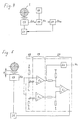
- Figure 4 shows the block diagram of the cable position sensor. It comprises a reference means 18 which sets reference thresholds of the detection signal s d and thus defines the proximity zones. For the definition of n consecutive proximity zones n-1 reference thresholds are required.
- a comparison unit 19 compares the detection signal s d with the reference thresholds and a signaling unit 20 produces an output signal s s which contains information on the area in which the cable is detected. This information generally identifies the area in which the cable is detected.
- the output signal s is coded so that it can be transmitted on a single signal line.
- the sensor comprises a control unit 21 which is able to inject in a circuit of the sensor for periodic control pulses, e.g., electrical voltage pulses, which are reflected in the output signal s s if the circuit between the point injection and the output works.
- control pulses are injected at the oscillator of the inductive measuring unit 17, so that the output signal contains information on the proper operation of the entire measurement, comparison and signaling chain.
- the control unit has at least two modes of operation that are distinguished by their repercussions in the output signal, which allows the observation of the operating mode of the control unit by observation of the output signal s s .
- the signaling unit controls the operating mode of the control unit (hereinafter referred to as "control mode") according to the zone z d in which the cable has been detected:
- the control mode is used to the coding of the output signal.
- the preferred control unit has the modes of operation “activated” and “deactivated”, which are characterized by the presence and absence of periodic control pulses respectively.
- the "activated” operating mode must then be selected when the cable is detected in a zone of work, that is to say a zone of proximity in which he can be found during the normal operation of installation. It is especially during the normal work of installation, that the operation of the sensor must be monitored.
- the signaling unit produces a signal of digital output, having either 0 or 0 base states 1, in which the control pulses are reflected by digital impulses.
- the simplest output signal then results if the signaling unit controls its state basic and control mode to encode information on the area in which the cable is detected. If the unit control has both "activated” operating modes and “disabled", the combinations with the basic states 0 and 1 of the output signal can distinguish four zones of proximity.
- a priori it would be possible to process the detection signal s d digitally, with a memory in which the reference thresholds would be recorded and a microcomputer for the comparison of the detection signal s d with these reference thresholds and the production a digital output signal.
- This approach would have the advantage that the sensor would be programmable, so that the size of the detection zones or other parameters could be easily adapted.
- a microcomputer and more generally any sequential logic circuit, may take an unexpected state in which it hangs.
- a circuit that contains only analog components and combinational logic elements is preferred. It is in this context that the command of the control mode according to the area in which the cable is detected is useful.
- the simplified diagram of such a sensor with three proximity zones is shown in Figure 5:
- the inductive measuring unit is analog and the detection signal s d it produces is a voltage u d .
- the reference means is a voltage divider which sets the reference voltages u ref1 and u ref2 .
- the comparison unit 19 comprises two voltage comparators c1, c2 for the comparison of u d with the reference voltages u ref1 and u ref2 respectively.
- the signaling unit 20 uses the output signal of the comparator c2 as such as an output signal s s of the sensor, which is only amplified by an output circuit 22.
- the output signal is derived from the output of the comparator c2 by a combinational logic circuit: Even a simple electrical conductor, which would connect the output of c2 directly with the plug of the connector 16 (see Figure 2) provided for the output signal, would be in this sense a combinatorial logic element.
- the control unit is deactivated when the cable is detected in z1 (u d ⁇ u ref1 ) or z3 (u d > u ref2 ) and only activated in case the cable is detected in the middle zone z2, c ' ie when u ref1 ⁇ u d ⁇ u ref2 .
- the comparator c3 of the signaling unit 20 produces for this purpose a digital signal which is 1 when the cable is detected in the zones z1 or z3 and which passes to 0 when it is detected in the proximity zone z2. Since the signals at the outputs of the comparators c1 and c2 are already digital, the circuit with the comparator c3 which deduces another digital signal is a combinational logic circuit.
- Figure 6 shows as a function of time different signals in a circuit according to the diagram of Figure 5, when the cable is moved away from the sensor at a constant speed.
- An exception is the first graph, which does not represent an electrical signal but the increase of the distance x between the cable 1 and the sensor surface 13.
- the second graph shows the detection voltage u d , which rises continuously as explained more high with reference to FIG.
- the reference means sets the reference voltages u ref1 and u ref2 and defines by this ticket reference distances x ref1 and x ref2 , which distribute the measurement field of the sensor into three consecutive proximity zones. Since the cable moves away continuously, three time periods T z1 , T z2 and T z3 can be distinguished, in which the cable is respectively in the zones z1, z2 and z3. During the period T z2, the control unit is activated and injects at the oscillating circuit of the measurement unit control pulses which are reflected by periodic voltage pulses 23 in the detection voltage u d .
- the following three graphs show the voltages u c1 u c2 and u c3 at the outputs of the comparators c1, c2 and c3.
- the control pulses are reflected at the output of the comparator c2 as digital pulses.
- This signal u c2 is the output signal of the sensor: the basic level of this signal (1 or 0) and the presence or absence of the control pulses makes it possible to say in which zone the cable is detected.
- the output of comparator c3 is only 0 if the cable is detected in zone z2. This signal controls the operating mode of the control unit. It also contains the repercussion of the control pulses, but that is no problem: since it is the control unit that produces these pulses, it can easily be designed so that it ignores their echo in the commanding signal. its mode of control.
- Figures 7 and 8 show the simplified construction of a pulley assembly of a transport facility, which has two pulleys 2a, 2b.
- the axes 25 of these pulleys are connected by two lateral elements 24, with which they form the support element of the assembly.
- the sensor of cable position 6 is fixed on this support element to near the pulley 2a. It is clear that such an assembly could also have only one pulley or, on the contrary, a larger number of pulleys.
Landscapes
- Measurement Of Length, Angles, Or The Like Using Electric Or Magnetic Means (AREA)
- Investigating Or Analyzing Materials By The Use Of Magnetic Means (AREA)
Applications Claiming Priority (2)
| Application Number | Priority Date | Filing Date | Title |
|---|---|---|---|
| CH19132003 | 2003-11-06 | ||
| CH19132003 | 2003-11-06 |
Publications (2)
| Publication Number | Publication Date |
|---|---|
| EP1530181A1 true EP1530181A1 (de) | 2005-05-11 |
| EP1530181B1 EP1530181B1 (de) | 2010-03-31 |
Family
ID=34427760
Family Applications (1)
| Application Number | Title | Priority Date | Filing Date |
|---|---|---|---|
| EP04405621A Expired - Lifetime EP1530181B1 (de) | 2003-11-06 | 2004-10-05 | Kabelpositionssensor |
Country Status (5)
| Country | Link |
|---|---|
| US (1) | US7432703B2 (de) |
| EP (1) | EP1530181B1 (de) |
| JP (1) | JP4883897B2 (de) |
| CN (1) | CN1614890B (de) |
| DE (1) | DE602004026260D1 (de) |
Cited By (2)
| Publication number | Priority date | Publication date | Assignee | Title |
|---|---|---|---|---|
| EP3319233A1 (de) * | 2016-11-08 | 2018-05-09 | ifm electronic gmbh | Induktiver näherungsschalter zur lageüberwachung eines transienten führenden drahtseils in einer seilbahn und dessen verwendung bei einer seilbahn |
| EP3336033A1 (de) * | 2016-12-19 | 2018-06-20 | KONE Corporation | Anordnung einer hebevorrichtung |
Families Citing this family (16)
| Publication number | Priority date | Publication date | Assignee | Title |
|---|---|---|---|---|
| JP4754799B2 (ja) * | 2004-10-08 | 2011-08-24 | 日本ケーブル株式会社 | 索道設備における索条位置異常検出装置 |
| JP4713313B2 (ja) * | 2005-11-24 | 2011-06-29 | 日本ケーブル株式会社 | 脱索事前検出装置 |
| DE102007006316B3 (de) * | 2007-01-30 | 2008-04-10 | Hima Paul Hildebrandt Gmbh + Co Kg | Vorrichtung und Verfahren zur Seillageüberwachung einer seilbetriebenen Transportanlage und seilbetriebene Transportanlage |
| US7764169B2 (en) * | 2008-03-12 | 2010-07-27 | Eaton Corporation | System for monitoring a plurality of sensors |
| DE102008015035A1 (de) * | 2008-03-13 | 2009-09-24 | Hima Paul Hildebrandt Gmbh + Co Kg | Verschleißüberwachungssystem, seilbetriebene Transportanlage und Verfahren zur Überwachung von Verschleißteilen derselben |
| US9678168B2 (en) * | 2009-11-16 | 2017-06-13 | Infineon Technologies Ag | Sensor system including multiple comparators |
| US20130220017A1 (en) * | 2012-02-23 | 2013-08-29 | Sung Kim | Non-destructive inspection apparatus for detecting internal defect of concrete structure using ultrasonic waves |
| CN106457004B (zh) * | 2014-03-12 | 2021-06-11 | 香港物流及供应链管理应用技术研发中心 | 制动器装置及其监控系统 |
| DE102015109549A1 (de) * | 2014-06-25 | 2015-12-31 | Ford Global Technologies, Llc | Näherungsschalteranordnung mit einer Furche zwischen benachbarten Näherungssensoren |
| CN105539514B (zh) * | 2015-12-02 | 2017-03-29 | 山东省科学院自动化研究所 | 一种往复式客运索道钢丝绳防缠绕系统及方法 |
| US9982668B2 (en) | 2016-08-17 | 2018-05-29 | Yanan Liu | Oil pumping apparatus |
| RU2735380C1 (ru) * | 2017-08-25 | 2020-10-30 | Иннова Патент Гмбх | Индуктивный сенсор |
| US11707645B2 (en) | 2018-05-22 | 2023-07-25 | Red Matter Labs, Inc. | Movement tracking devices and methods |
| AT522584B1 (de) * | 2019-05-28 | 2020-12-15 | Innova Patent Gmbh | Verfahren zum Erfassen eines Verschleißes einer Seilrolle einer Seilbahnanlage |
| EP4065498A4 (de) * | 2019-11-27 | 2023-07-26 | KONE Corporation | Steuerung eines aufzugssystems |
| DE102023125198A1 (de) * | 2023-09-18 | 2025-03-20 | Semperit Ag Holding | Einlagenelement mit digitaler Markierung zur Anwendung in einer Seilbahn |
Citations (1)
| Publication number | Priority date | Publication date | Assignee | Title |
|---|---|---|---|---|
| US5977662A (en) * | 1996-05-20 | 1999-11-02 | I F M Electronic Gmbh | Electronic switching device and circuits with a plurality of such switching devices |
Family Cites Families (12)
| Publication number | Priority date | Publication date | Assignee | Title |
|---|---|---|---|---|
| CH655414B (de) * | 1981-07-17 | 1986-04-15 | ||
| JPH0785984B2 (ja) * | 1989-03-03 | 1995-09-20 | 川鉄マシナリー株式会社 | 運搬設備における脱索位置検出表示装置 |
| JPH04133972U (ja) * | 1991-06-04 | 1992-12-14 | 日本ケーブル株式会社 | 索道の受索輪ライナー |
| DE69228697T2 (de) * | 1991-11-29 | 1999-07-29 | Cosmo System Corp., Matsumoto, Nagano | Positionsänderung bei einer transportvorrichtung und antriebsregler für ein transportelement |
| EP0629834B1 (de) * | 1992-03-02 | 1999-06-02 | Seiko Epson Corporation | Verschiebungssensor |
| JPH06227388A (ja) * | 1993-02-04 | 1994-08-16 | Mitsubishi Heavy Ind Ltd | 索条位置検出装置 |
| US5548212A (en) * | 1993-10-29 | 1996-08-20 | Logue; Delmar L. | Thickness and hardness measurement apparatus utilizing a rotating induction vector |
| CH690950A5 (de) * | 1996-06-13 | 2001-02-28 | Optosys Ag | Temperaturstabilisierter Oszillator und Verwendung desselben in einem Näherungsschalter. |
| JPH10119763A (ja) * | 1996-10-21 | 1998-05-12 | Nippon Cable Co Ltd | 索道における脱索事前検出装置 |
| JP2927748B2 (ja) * | 1996-12-10 | 1999-07-28 | 近畿日本鉄道株式会社 | 支索外径測定方法およびその装置 |
| DE19752362A1 (de) * | 1997-11-26 | 1999-06-17 | Doppelmayr Seilbahn Produktion | Schaltungsanordnung zur Überwachung des fehlerfreien und/oder zur Erkennung eines fehlerbehafteten Zustands einer Anlage |
| JP2001302092A (ja) * | 2000-04-14 | 2001-10-31 | Murata Mach Ltd | トラバース装置 |
-
2004
- 2004-10-05 EP EP04405621A patent/EP1530181B1/de not_active Expired - Lifetime
- 2004-10-05 DE DE602004026260T patent/DE602004026260D1/de not_active Expired - Lifetime
- 2004-11-05 US US10/983,049 patent/US7432703B2/en not_active Expired - Fee Related
- 2004-11-05 CN CN200410092246.2A patent/CN1614890B/zh not_active Expired - Fee Related
- 2004-11-05 JP JP2004321792A patent/JP4883897B2/ja not_active Expired - Fee Related
Patent Citations (1)
| Publication number | Priority date | Publication date | Assignee | Title |
|---|---|---|---|---|
| US5977662A (en) * | 1996-05-20 | 1999-11-02 | I F M Electronic Gmbh | Electronic switching device and circuits with a plurality of such switching devices |
Cited By (2)
| Publication number | Priority date | Publication date | Assignee | Title |
|---|---|---|---|---|
| EP3319233A1 (de) * | 2016-11-08 | 2018-05-09 | ifm electronic gmbh | Induktiver näherungsschalter zur lageüberwachung eines transienten führenden drahtseils in einer seilbahn und dessen verwendung bei einer seilbahn |
| EP3336033A1 (de) * | 2016-12-19 | 2018-06-20 | KONE Corporation | Anordnung einer hebevorrichtung |
Also Published As
| Publication number | Publication date |
|---|---|
| CN1614890A (zh) | 2005-05-11 |
| US20050099176A1 (en) | 2005-05-12 |
| DE602004026260D1 (de) | 2010-05-12 |
| US7432703B2 (en) | 2008-10-07 |
| EP1530181B1 (de) | 2010-03-31 |
| JP2005138833A (ja) | 2005-06-02 |
| CN1614890B (zh) | 2010-05-05 |
| JP4883897B2 (ja) | 2012-02-22 |
Similar Documents
| Publication | Publication Date | Title |
|---|---|---|
| EP1530181B1 (de) | Kabelpositionssensor | |
| EP0048188B1 (de) | Vorrichtung zum Überwachen eines endlosen Förderbandes | |
| CN101516746B (zh) | 链条磨损监控装置 | |
| EP1142077A1 (de) | Schutzvorrichtung für ein von einem elektromotor angetriebenen schiebefenster und installationsverfahren einer solchen vorrichtung | |
| FR2670889A1 (fr) | Escaliers bois cremaillere anglaise, poteaux, lisses, gardecorps a fabrication et pose simplifiee. | |
| RU2578902C2 (ru) | Устройство для перемещения людей и/или объектов | |
| CN101633474B (zh) | 自动扶梯的安全装置 | |
| CA2473992C (en) | Wear measurement device | |
| EP2441706B1 (de) | Detektionseinrichtung für eine Fördereinrichtung | |
| EP3317137A1 (de) | Überwachung des zustandes eines stromabnehmerstreifens zum reiben gegen einen oberleitungsdraht | |
| EP3814807B1 (de) | Tragbares detektionssystem mit magnetostatischen sensoren | |
| JP5503224B2 (ja) | コンベアベルト及びベルトコンベア装置 | |
| US10689231B2 (en) | Belt safety device and people conveyor with a belt safety device | |
| FR2830653A1 (fr) | Capteur infrarouge actif multietage | |
| WO2021250132A1 (fr) | Procédé et dispositif de contrôle d'une installation de transport par câble et installation comprenant un tel dispositif de contrôle | |
| EP0601147B1 (de) | Sicherheitvorrichtung für lasermachine und verfahren zur durchführung der vorrichtung | |
| EP4499382A1 (de) | Verfahren zum entladen von mindestens einem spannteil, zugehöriges spannsystem und ladeverfahren | |
| FR3111986A1 (fr) | Dispositif de guidage et système mécanique comprenant un tel dispositif | |
| EP4143531B1 (de) | Führungsgerät und mechanisches system einschliesslich eines solchen geräts | |
| EP3814809B1 (de) | Tragbares detektionssystem mit magnetostatischen sensoren | |
| FR2665263A1 (fr) | Procede et dispositif de controle de defauts de tubes metalliques en cours de laminage a chaud par courants de foucault. | |
| FR2520525A1 (fr) | Perfectionnements aux dispositifs de controle du mouvement d'un objet mobile en translation | |
| CA1177939A (fr) | Installation pour la surveillance d'un convoyeur a tapis sans fin | |
| CN103527178B (zh) | 液压抓斗的测深装置 | |
| WO2000073871A1 (fr) | Dispositif et procede de controle et/ou de commande d'au moins un organe tel qu'un moteur, un verin ou un compteur |
Legal Events
| Date | Code | Title | Description |
|---|---|---|---|
| PUAI | Public reference made under article 153(3) epc to a published international application that has entered the european phase |
Free format text: ORIGINAL CODE: 0009012 |
|
| AK | Designated contracting states |
Kind code of ref document: A1 Designated state(s): AT BE BG CH CY CZ DE DK EE ES FI FR GB GR HU IE IT LI LU MC NL PL PT RO SE SI SK TR |
|
| AX | Request for extension of the european patent |
Extension state: AL HR LT LV MK |
|
| 17P | Request for examination filed |
Effective date: 20050826 |
|
| AKX | Designation fees paid |
Designated state(s): CH DE FR GB IT LI |
|
| 17Q | First examination report despatched |
Effective date: 20071219 |
|
| GRAP | Despatch of communication of intention to grant a patent |
Free format text: ORIGINAL CODE: EPIDOSNIGR1 |
|
| GRAS | Grant fee paid |
Free format text: ORIGINAL CODE: EPIDOSNIGR3 |
|
| GRAA | (expected) grant |
Free format text: ORIGINAL CODE: 0009210 |
|
| AK | Designated contracting states |
Kind code of ref document: B1 Designated state(s): CH DE FR GB IT LI |
|
| REG | Reference to a national code |
Ref country code: GB Ref legal event code: FG4D Free format text: NOT ENGLISH Ref country code: CH Ref legal event code: EP |
|
| REF | Corresponds to: |
Ref document number: 602004026260 Country of ref document: DE Date of ref document: 20100512 Kind code of ref document: P |
|
| PLBE | No opposition filed within time limit |
Free format text: ORIGINAL CODE: 0009261 |
|
| STAA | Information on the status of an ep patent application or granted ep patent |
Free format text: STATUS: NO OPPOSITION FILED WITHIN TIME LIMIT |
|
| 26N | No opposition filed |
Effective date: 20110104 |
|
| PG25 | Lapsed in a contracting state [announced via postgrant information from national office to epo] |
Ref country code: IT Free format text: LAPSE BECAUSE OF FAILURE TO SUBMIT A TRANSLATION OF THE DESCRIPTION OR TO PAY THE FEE WITHIN THE PRESCRIBED TIME-LIMIT Effective date: 20100331 |
|
| REG | Reference to a national code |
Ref country code: CH Ref legal event code: PL |
|
| GBPC | Gb: european patent ceased through non-payment of renewal fee |
Effective date: 20101005 |
|
| PG25 | Lapsed in a contracting state [announced via postgrant information from national office to epo] |
Ref country code: LI Free format text: LAPSE BECAUSE OF NON-PAYMENT OF DUE FEES Effective date: 20101031 Ref country code: CH Free format text: LAPSE BECAUSE OF NON-PAYMENT OF DUE FEES Effective date: 20101031 Ref country code: FR Free format text: LAPSE BECAUSE OF NON-PAYMENT OF DUE FEES Effective date: 20101102 |
|
| REG | Reference to a national code |
Ref country code: FR Ref legal event code: ST Effective date: 20110630 |
|
| PG25 | Lapsed in a contracting state [announced via postgrant information from national office to epo] |
Ref country code: GB Free format text: LAPSE BECAUSE OF NON-PAYMENT OF DUE FEES Effective date: 20101005 |
|
| PGFP | Annual fee paid to national office [announced via postgrant information from national office to epo] |
Ref country code: DE Payment date: 20221019 Year of fee payment: 19 |
|
| P01 | Opt-out of the competence of the unified patent court (upc) registered |
Effective date: 20230502 |
|
| REG | Reference to a national code |
Ref country code: DE Ref legal event code: R119 Ref document number: 602004026260 Country of ref document: DE |
|
| PG25 | Lapsed in a contracting state [announced via postgrant information from national office to epo] |
Ref country code: DE Free format text: LAPSE BECAUSE OF NON-PAYMENT OF DUE FEES Effective date: 20240501 |