EP3814809B1 - Tragbares detektionssystem mit magnetostatischen sensoren - Google Patents
Tragbares detektionssystem mit magnetostatischen sensoren Download PDFInfo
- Publication number
- EP3814809B1 EP3814809B1 EP19733506.0A EP19733506A EP3814809B1 EP 3814809 B1 EP3814809 B1 EP 3814809B1 EP 19733506 A EP19733506 A EP 19733506A EP 3814809 B1 EP3814809 B1 EP 3814809B1
- Authority
- EP
- European Patent Office
- Prior art keywords
- detector
- value
- sensors
- average value
- passive
- Prior art date
- Legal status (The legal status is an assumption and is not a legal conclusion. Google has not performed a legal analysis and makes no representation as to the accuracy of the status listed.)
- Active
Links
Images


Classifications
-
- G—PHYSICS
- G01—MEASURING; TESTING
- G01V—GEOPHYSICS; GRAVITATIONAL MEASUREMENTS; DETECTING MASSES OR OBJECTS; TAGS
- G01V3/00—Electric or magnetic prospecting or detecting; Measuring magnetic field characteristics of the earth, e.g. declination, deviation
- G01V3/08—Electric or magnetic prospecting or detecting; Measuring magnetic field characteristics of the earth, e.g. declination, deviation operating with magnetic or electric fields produced or modified by objects or geological structures or by detecting devices
- G01V3/081—Electric or magnetic prospecting or detecting; Measuring magnetic field characteristics of the earth, e.g. declination, deviation operating with magnetic or electric fields produced or modified by objects or geological structures or by detecting devices the magnetic field is produced by the objects or geological structures
-
- G—PHYSICS
- G01—MEASURING; TESTING
- G01V—GEOPHYSICS; GRAVITATIONAL MEASUREMENTS; DETECTING MASSES OR OBJECTS; TAGS
- G01V3/00—Electric or magnetic prospecting or detecting; Measuring magnetic field characteristics of the earth, e.g. declination, deviation
- G01V3/08—Electric or magnetic prospecting or detecting; Measuring magnetic field characteristics of the earth, e.g. declination, deviation operating with magnetic or electric fields produced or modified by objects or geological structures or by detecting devices
- G01V3/10—Electric or magnetic prospecting or detecting; Measuring magnetic field characteristics of the earth, e.g. declination, deviation operating with magnetic or electric fields produced or modified by objects or geological structures or by detecting devices using induction coils
- G01V3/104—Electric or magnetic prospecting or detecting; Measuring magnetic field characteristics of the earth, e.g. declination, deviation operating with magnetic or electric fields produced or modified by objects or geological structures or by detecting devices using induction coils using several coupled or uncoupled coils
-
- G—PHYSICS
- G01—MEASURING; TESTING
- G01V—GEOPHYSICS; GRAVITATIONAL MEASUREMENTS; DETECTING MASSES OR OBJECTS; TAGS
- G01V3/00—Electric or magnetic prospecting or detecting; Measuring magnetic field characteristics of the earth, e.g. declination, deviation
- G01V3/15—Electric or magnetic prospecting or detecting; Measuring magnetic field characteristics of the earth, e.g. declination, deviation specially adapted for use during transport, e.g. by a person, vehicle or boat
- G01V3/165—Electric or magnetic prospecting or detecting; Measuring magnetic field characteristics of the earth, e.g. declination, deviation specially adapted for use during transport, e.g. by a person, vehicle or boat operating with magnetic or electric fields produced or modified by the object or by the detecting device
-
- G—PHYSICS
- G01—MEASURING; TESTING
- G01V—GEOPHYSICS; GRAVITATIONAL MEASUREMENTS; DETECTING MASSES OR OBJECTS; TAGS
- G01V3/00—Electric or magnetic prospecting or detecting; Measuring magnetic field characteristics of the earth, e.g. declination, deviation
- G01V3/38—Processing data, e.g. for analysis, for interpretation, for correction
Definitions
- the invention relates to the field of detection of target objects, and more particularly to the detection of objects comprising magnetized or ferromagnetic elements.
- Such barriers generally comprise a post fixed on a base and equipped with at least one magnetostatic sensor, for example three magnetostatic sensors distributed over the height of the post. Each sensor is configured to generate a signal (voltage) indicative of an intensity of a detected electromagnetic field.
- These Barriers are used in prisons to detect whether prisoners are carrying magnetic objects, particularly mobile phones. For this purpose, the sensitivity of magnetic sensors can be very high, as prisoners are normally deprived of any metallic or magnetic material.
- the document WO 2011/020148 describes a system for detecting a target object comprising separate detectors comprising at least one magnetic sensor configured to generate a signal indicative of an intensity of a detected magnetic field, and a processing unit 20 configured to receive the signals generated by the magnetic sensors.
- This document relates in particular to the field of coil detectors, combined with another detection technology in order to improve detection.
- the document US 2018/012465 describes a detection system comprising detectors each comprising at least one magnetic sensor configured to generate a signal indicative of an intensity of a detected magnetic field and, for each detector, a processing unit configured to receive the signals indicative of an intensity of a magnetic field detected by the sensors. Since the magnetic field produced at a detector is inversely proportional to the cube of the sensitivity distance r of a detector, the two detectors of the system of this document are spaced apart by a length equal to half their sensitivity distance. In this way, the detectors are independent and their sensitivities can be reduced.
- the document US 2006/197523 describes a system for detecting an object comprising several detectors each comprising several gradiometers and a processor configured to collect signals generated by the gradiometers.
- the processor calculates an average value of the collected signals to obtain a measure of the background noise. This average is then subtracted from the signals generated by the gradiometers to eliminate the noise.
- the document WO 2011/020148 describes an inspection system for detecting a threat within an object, the system comprising a conveyor belt for moving said object in a first direction through a detection volume, at least two inspection subsystems positioned along the first direction, wherein at least one inspection subsystem transmits electromagnetic pulses to the object and wherein both inspection subsystems detect electromagnetic fields generated by the object.
- a computer receives data indicative of the detected electromagnetic fields, generates a signal based on the data, and compares the signals to predetermined thresholds.
- An objective of the invention is therefore to propose a detection system that can be installed and uninstalled quickly, for example at the entrance to public places, which is capable of reliably discriminating small objects comprising magnetic elements, such as smartphones, and of detecting assault rifles for a reasonable size.
- the invention proposes a system according to claim 1.
- the invention also provides a method according to claim 6.
- Each detector 10, 20 comprises at least one magnetic sensor 5.
- magnetic (or magnetostatic) sensor we mean here a passive sensor configured to detect a magnetic field which naturally surrounds objects comprising iron or any other ferromagnetic element, as opposed for example to an inductive winding.
- the first detector 10 comprises at least one first magnetic sensor 5, preferably at least two, for example three first magnetic sensors 5, while the second detector 20 comprises at least one second magnetic sensor 5.
- the second detector 20 and the first detector 10 each comprise as many sensors 5.
- Each magnetic sensor 5 is configured to detect a magnetic field and generate a signal indicative of an intensity of the magnetic field thus detected.
- the signal is a voltage whose value is proportional to the intensity of the detected magnetic field.
- each magnetic sensor 5 is configured to detect an intensity of a magnetic field along three orthogonal axes.
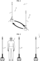
- Each detector 10, 20 further comprises a post 3, configured to be placed on the ground, for example via a base 4.
- a height of the post 3 is substantially equal to an average height of a person 2, for example of the order of 1.70 m to 2.0 m.
- each detector 10, 20 can be equipped with a handle in order to facilitate its transport.
- the handle can in particular be fixed on the base 4.
- each post 3 can be equipped with three magnetic sensors 5, distributed between the base 4 and the free end of the post 3.
- the magnetic sensors of the detectors 10, 20 are positioned two by two at the same height so as to form pairs of sensors 5 facing each other.
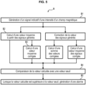
- the system 1 further comprises at least one processing unit 6 configured to receive the signals indicative of an intensity of a magnetic field generated by the first magnetic sensor 5 and/or the second magnetic sensor 5. The processing unit 6 then determines an average value of the signals generated by the magnetic sensors 5 of the first and second detectors 10, 20 and, when said average value is greater than a predetermined threshold value, sends instructions for sending an alarm.
- the processing unit 6 determines an arithmetic mean value of the signals, which corresponds to the sum of the values of the signals divided by the number of signals.
- the processing unit 6 determines a geometric mean value of the signals, which corresponds to the square root of the product of the signals.
- the processing unit 6 may be integrated into one of the first detector 10 and the second detector 20.
- each detector 10, 20 comprises an integrated processing unit 6.
- the processing unit 6 is part of the detector 10, 20 and is not a separate element to which the system 1 is connected.
- the processing unit 6 can for example be fixed on the post 3 of the associated detector, or alternatively in its base 4.
- the processing unit 6 can be placed at a distance from the first and second detectors 10, 20.
- the detectors 10, 20 then communicate to it the signals generated by their magnetic sensors 5 for processing via their communication interface 7.
- the SMM is connected to at least one transmitter 8 configured to generate an alarm signal, for example an acoustic transmitter 8 configured to generate an acoustic signal and/or a light configured to generate an optical signal (LED, flashing lamp, etc.).
- the transmitter 8 may be included in the detector 10, 20, or alternatively be worn by an operator (earpiece, etc.) in which case the processing unit 6 sends the instructions for generating an alarm to the remote transmitter 8 via the communication interface 7 of the corresponding detector 10, 20.
- the SMM is further connected to an asynchronous UART interface to enable connection of the processing unit 6 to a computer (or equivalent) to authorize various actions including control of the detection program, diagnosis of one or more detectors, loading of updates, etc.
- HMI human machine interface
- the communication interface 7 preferably comprises a wireless interface in order to facilitate the installation of the detection system 1, for example an interface of the Wi-Fi, Bluetooth type, by optical, radio, infrared or even inductive communication, etc.
- the communication interface 7 can be wired.
- the detection system 1 may comprise a third detector 30 comprising at least one third magnetic sensor 5 configured to detect a magnetic field and generate a signal indicative of an intensity of the magnetic field thus detected.
- the third detector 30 may comprise a post 3 fixed on a base 4 and equipped with the third magnetic sensor(s) 5 as well as a communication interface 7 and, where appropriate, a processing unit 6.
- the invention proposes to place the first detector 10, the second detector 20 and the third detector 30 side by side so as to form two gates. More precisely, the first gate is formed by the first detector 10 and the second detector 20, while the second gate is formed by the second detector 20 and the third detector 30.
- the same detector here, the second detector 20
- the same detector is therefore used for the formation of two separate gates, which makes it possible to significantly reduce the size of the detection system 1 in comparison, for example, with the system proposed in the document WO 2017/141022 .
- the system is also easier to set up.
- the processing unit 6 of the second detector 20, which is located between the first detector 10 and the second detector 20, can be configured both to process the signals generated by the magnetic sensor(s) 5 of the third detector 30 and to communicate with the first detector 10, so that the detection system 1 is capable of determining the door within which a target object has been detected, despite the fact that the magnetic sensors 5 perform scalar and not vector detection.
- an operator can also use four detectors according to the invention in order to form two doors, the pooling of the second detector 20 not being obligatory for the detection of target objects.
- Each detector 10, 20 may further comprise identification means and a memory in order to allow association and communication with the other detectors of the detection system 1 as well as the implementation of the detection method S.
- each detector 10, 20, 30 may be assigned an address, which may be fixed at the time of manufacture of the detector 10, 20, 30 or programmed at the time of pairing of the detectors 10, 20, 30 forming the detection system 1.
- the address of each detector 10, 20, 30 is fixed, i.e. cannot be modified, in order to limit handling errors of the detection system 1 and to facilitate after-sales service.
- An example of an address may include a string of characters that may include a given number of hexadecimal pairs, for example eight.
- the detection system 1 comprises a first detector 10 and a second detector 20 comprising two first magnetic sensors 5 and two second magnetic sensors 5, respectively.
- the first and second magnetic sensors 5 form two pairs of magnetic sensors 5, each pair comprising a first sensor 5 and a second sensor 5.
- one pair comprises a first magnetic sensor 5 and a second magnetic sensor 5 placed near a free end of the post 3 of the first detector 10 and the second detector 20, while the other pair comprises a first magnetic sensor 5 and a second magnetic sensor 5 placed near their base 4.
- the two detectors are identical and each comprise a processing unit 6 and a communication interface 7.
- the invention applies mutatis mutandis in the case where the detectors comprise a different number of magnetic sensors 5.
- the detectors could comprise only one magnetic sensor 5, or more than two magnetic sensors 5 (for example three magnetic sensors 5).
- the second detector 20 could not comprise a processing unit 6, or alternatively the processing unit 6 could be placed at a distance from the detectors instead of being housed in the first detector 10.
- the first and second detectors 10, 20 are paired to associate them and configured so as to assign to each a function in the detection method S.
- the first detector 10 can be configured as a master detector while the second detector 20 is configured as a slave detector.
- master detector of a given gate we will understand here the detector whose processing unit 6 is configured to calculate the average value and/or the corrected value of the signal, while by slave detector, we will understand the other detector of said given gate.
- At least one of the first and second magnetic sensors 5 generates a signal indicative of the intensity of a magnetic field.
- the signals generated by the first and second magnetic sensors 5 are transmitted to the processing unit 6, where appropriate via the communication interfaces 7 of the first detector 10 and/or the second detector 20.
- the first detector 10 being master and comprising the processing unit 6, the signals from the second magnetic sensors 5 are transmitted to the first detector 10 via the communication interface 7 of the second detector 20, while the signals from the first magnetic sensors 5 can be transmitted to it directly by the first magnetic sensors 5.
- the processing unit 6 of the master detector then calculates an average value of the signals generated by each pair of magnetic sensors 5.
- the processing unit 6 therefore calculates a first average value corresponding to a first of the pairs of first and second magnetic sensors 5, and a second average value corresponding to the second of the pairs.
- the processing unit 6 calculates only one average value in step S2 corresponding to the average value of the signals from these two magnetic sensors 5.
- the processing unit 6 can calculate an arithmetic mean value of the signals or, alternatively, a geometric mean value.
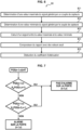
- the processing unit 6 can implement a step S3 of correcting the signals generated by each of the magnetic sensors 5 by applying an attenuation coefficient to said signals.
- This correction step S3 thus makes it possible to attenuate the signals generated by the magnetic sensors 5 of the detection system 1 by applying a correction coefficient to the signals depending on the value of these signals. More precisely, the objective of the correction is to attenuate the signal when the target object is close to one of the detectors 10, 20, where the sensitivity is higher, in order to reduce its weight in the detection.
- the processing unit 6 determines the maximum value and the minimum value among the signals generated by the first magnetic sensor 5 and the second magnetic sensor 5 at a given time.
- the processing unit 6 calculates a ratio between the maximum value and the minimum value thus determined, then, during a fourth sub-step S34, compares the ratio to determined thresholds and deduces the value of the attenuation coefficient to be applied to the value of the signals.
- the ratio of the maximum to the minimum value it is possible to determine whether the target object that generates a magnetic field or disturbs the Earth's electromagnetic field is placed near one of the detectors.
- the value of the ratio is greater than the second threshold and the attenuation coefficient that is applied is equal to the second value, which is less than the first value.
- the sensitivity of the gate in this area is lower. This results in a ratio between the maximum and minimum value that is also lower.
- the attenuation coefficient can therefore be higher and the resulting attenuation lower.
- the first threshold may be equal to 30, the second threshold may be equal to 60, the first value may be equal to 1, the second value may be equal to 0.1 and the attenuation coefficient may be defined by the following function when the ratio is between the first threshold and the second threshold: ⁇ 0 ,03 * R + 1 ,9 where R is the value of the ratio.
- the attenuation coefficient can be equal to 1 when the ratio is less than 30, 0.1 when the ratio is greater than 60, and - 0.03*R + 1.9 when the ratio is between 30 and 60.
- the processing unit 6 can both calculate an average of the signals for each pair of magnetic sensors 5 (step S2) and implement a step of correction of said signals (step S3).
- the processing unit 6 can apply an attenuation coefficient to the average values thus calculated (step S3).
- the processing unit 6 can first apply the attenuation coefficient to the signals of each pair of magnetic sensors 5 (step S3) and then calculate an average of the corrected signals of each pair of magnetic sensors 5 (step S2, applied to the corrected signals and not to the signals generated by the magnetic sensors 5).
- the attenuation coefficient can be the same as described above (equal to the first value, the second value or a function of the ratio, depending on the value of the ratio).
- the processing unit 6 compares the calculated value to a predetermined threshold value.
- the calculated value used by the processing unit 6 during the fifth step S5 may be either the average value of the signals generated by the pairs of magnetic sensors 5 and obtained in step S2, or the average value corrected by applying an attenuation coefficient following step S3.
- the processing unit 6 sends transmission instructions of an alarm (optical, audible, etc.) to at least one of the transmitters 8.
- the processing unit 6 sends instructions for transmitting an alarm to the transmitters 8 of the first detector 10 and of the second detector 20 (via the communication interfaces 7), so that one or more alarms are transmitted on both sides of the door.
- only the transmitter(s) 8 of one of the detectors 10, 20 can receive the transmission instructions from the processing unit 6.
- the processing unit 6 determines only a corrected value of the signals, without averaging them, it is the sum of the corrected values of the signals (and not their average) which is compared during step S5 with the predetermined threshold value.
- the signals generated by the sensors 5 can first be summed before the correction step S3 is applied to them.
- the processing unit 6 can determine the maximum value of the corrected signals and compare, during step S5, the maximum value thus determined with the threshold value. In a manner similar to what was described previously, it is possible to first determine the maximum value of the signals generated by the sensors 5 and then apply the correction step S3 to this maximum value.
- the processing unit 6 compares the sum of the corrected values (respectively, the corrected maximum value) of the signals of the same pair of magnetic sensors 5 with the predetermined threshold value. When this sum (respectively, this corrected maximum value) is greater than the predetermined threshold value, during the sixth step S6, the processing unit 6 sends instructions for transmitting an alarm (optical, audible, etc.) to at least one of the transmitters 8. As indicated previously, the processing unit 6 can send instructions for transmitting an alarm to the transmitters 8 of the first detector 10 and/or of the second detector 20.
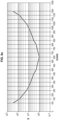
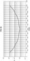
- FIGS. 8a , 8b And 8c illustrate the signal intensity measured for four detection systems as a function of distance from the detector(s).
- FIG. 8a illustrates the case of a detection system according to the prior art comprising two detectors separated by a distance of 130 cm.
- the intensity represented corresponds to the maximum value of the signals generated by the sensors of the two detectors.
- FIG. 8b illustrates the case of a detection system 1 according to an embodiment of the invention comprising two detectors separated by a distance of 130 cm and comprising a processing unit.
- the intensity represented corresponds to the average value of the signals generated by the sensors of the two detectors.
- FIG. 8c illustrates the case of a detection system 1 according to an embodiment of the invention comprising two detectors separated by a distance of 130 cm and comprising a processing unit.
- the intensity represented corresponds to the corrected average value of the signals generated by the sensors of the two detectors.
- the table below is a comparative example of detection of the same target object by three configurations of detection system 1, namely (i) a detection system 1 comprising only one detector, (ii) a detection system 1 according to a first embodiment of the invention and comprising two detectors spaced 130 cm apart with calculation of the average value of the signals and (iii) a detection system 1 according to a second embodiment of the invention and comprising two detectors spaced 130 cm apart with calculation of the average value of the signals. and correcting said average value to determine whether an alarm should be triggered.
- the SE sensitivity of the three detection system configurations was set to 85% (corresponding to 1400 mV). In other words, the sensitivity was set so that the predetermined threshold value was equal to 1400 mV.
- the systems were configured so that at this sensitivity, the passage of a 75 mm diameter sphere at a height of one meter from the ground does not generate an alarm when it passes 65 cm from the single detector (first configuration (i)) or in the middle of the two detectors (second and third configurations (ii) (iii)). In other words, the 75 mm diameter is a limit diameter for detection by the systems tested.
- the disturbance of the electromagnetic field of an iron sphere with a diameter of 75 mm corresponds approximately to the disturbance generated by the presence of an AK47 type assault rifle in the center of the door.
- Limit diameter [mm] Limit diameter [mm] Limit diameter [mm] Distance between the sphere and one of the detectors [cm] (i) Single detector (ii) Two-detector system with averaging (iii) Two-detector system with mean value calculation and mean value correction 10 11 18 35 15 18 23 50 20 23 30 60 25 30 35 64 30 35 40 69 35 40 50 75 40 45 55 64 45 50 60 64 50 60 62 62 55 64 64 64 60 69 69 65 75 75 75 75
- limit diameter [mm] corresponds to the minimum diameter in millimeters from which the detection system 1 tested emits an alarm signal.
- the detection system 1 comprises two detectors forming a door (configurations (ii) and (iii)) and the processing unit 6 calculates the average value of the signals generated by the magnetic sensors 5 of these detectors, it is capable of discriminating target objects whose magnetic field is equivalent to that of an iron sphere of approximately 62 mm from smaller objects such as smartphones, even if the target object is 50 cm from one of the detectors (which, in practice, is already quite far from the center of the passage, the detectors being spaced 130 cm apart during this test).
- the detection system 1 is also capable of discriminating target objects whose magnetic field is equivalent to that of a sphere of approximately 64 mm, even if the target object is 25 cm from one of the detectors (i.e. very close to it, the detectors being spaced 130 cm apart during this test).
- the detection systems according to the invention are therefore capable of discriminating between small objects, even if these include magnetic elements (such as smartphones) and large-volume target objects such as assault rifles, even if the passage of the person 2 inspected is not centered between the detectors.
- the invention also applies to the case where the detection system 1 comprises a number of detectors greater than or equal to three so as to form a plurality of doors and where two adjacent doors share the same detector.
- An example of a method for detecting a target object using such a detection system 1 will now be described.
- the detection system 1 comprises three detectors each comprising two sensors. magnetic 5 ( figure 3 ).
- the detection system 1 comprises a first, a second and a third detector 10, 20, 30, comprising two first, two second and two third magnetic sensors 5, respectively.
- the second detector 20 forms a first gate with the first detector 10 and a second gate with the third detector 30.
- the second detector 20 is therefore located between the first detector 10 and the third detector 30.
- the three detectors are identical and therefore each comprise a processing unit 6 and a communication interface 7.
- the processing unit 6 could alternatively be placed at a distance from the detectors and not be integrated into the detectors.
- the signals generated by the magnetic sensors 5 of a given detector are transmitted to the remote processing unit 6 via the communication interfaces 7 of the detectors so that it applies the detection algorithm to them and then transmits any alarm generation instructions to the transmitters 8 of the detectors, via their respective communication interfaces 7.
- the invention applies mutatis mutandis in the case where the system comprises only two detectors together forming a single gate or a larger number of detectors (for example n detectors, n being an integer) together forming n - 1 gates.
- the detectors could further comprise only one magnetic sensor 5, or more than two magnetic sensors 5 (for example three magnetic sensors 5).
- the first, second and third detectors 10, 20, 30 are paired to associate them and configured to assign each a function in the detection method S.
- the first detector 10 may be configured as a master detector while the second detector 20 is configured as a slave detector.
- the second detector 20 is configured as a master detector while the third detector 30 is configured as a slave detector.
- the identification means of each detector of the system typically, their address
- the identification means of the first detector 10 are informed in the second detector 20 while the identification means of the second detector 20 are informed in the first detector 10 so as to allow their pairing.
- the identification means of the second detector 20 are informed in the third detector 30, while the identification means of the third detector 30 are informed in the second detector 20.
- At least one of the first, second and third magnetic sensors 5 detects a magnetic field and generates a signal indicative of the intensity of the magnetic field thus detected.
- all the magnetic sensors 5 of the same door generate, continuously or periodically, a signal representative of the intensity of a magnetic field, only the power of the signal generated by each sensor 5 being different.
- the signal generated by the magnetic sensors 5 is then transmitted to the processing unit 6 of the master detector of the door concerned, if necessary via communication interfaces 7.
- the signal generated by the third magnetic sensors 5 is transmitted by the communication interface 7 of the third detector 30 to the processing unit 6 of the second detector 20.
- the signal generated by the second magnetic sensors 5 is transmitted directly to the processing unit 6 of the second detector 20 (knowing that it would be transmitted via its communication interface 7 in the case where the processing unit 6 is external).
- the processing unit 6 of the master detector of the door concerned calculates an average value PGS[2, 3] of the signals generated for each pair of magnetic sensors 5.
- the processing unit 6 therefore calculates a first average value corresponding to a first of the pairs of second and third magnetic sensors 5 and a second average value corresponding to the second of the pairs.
- the processing unit 6 calculates only one average value corresponding to the average value of the signals from these two magnetic sensors 5.
- the processing unit 6 can calculate an arithmetic mean value of the signals or, alternatively, a geometric mean value.
- the processing unit 6 can implement a step of correcting the signals generated by each of the magnetic sensors 5 by applying an attenuation coefficient to said signals, then calculate a value corresponding to the sum of the values of the signals thus corrected (or alternatively determine the maximum value of the corrected signals, for each pair of sensors 5).
- This correction step having already been described above in relation to sub-steps S31 to S35, it will not be detailed further here.
- the processing unit 6 can both calculate an average value of the signals for each pair of magnetic sensors 5 and implement a step of correcting said signals, as described above so as to obtain a corrected average value.
- the correction step S2 can be applied either to the signals generated by the sensors 5, or to the sum of the signals (or to their maximum value), or to the average value of the signals.
- the processing unit 6 of the second detector 20 transmits to the processing unit 6 of the first detector 10 on the one hand said calculated value PGS[2, 3] and on the other hand the signals generated by its second magnetic sensors 5.
- the processing unit 6 of the first detector 10 calculates a PGS[1, 2] value from the signals generated for each pair of magnetic sensors 5 of the first gate.
- the calculation of the value performed by the processing unit 6 of the first detector 10 is the same as that performed by the processing unit 6 of the second detector 20.
- the other master detectors perform the same calculation (respectively, calculation of the average value, of a corrected average value, of a value corresponding to the sum of the corrected values or of a corrected maximum value).
- the processing unit 6 of the first detector 10 calculates for example a first average value corresponding to a first of the pairs of first and second magnetic sensors 5, and a second average value corresponding to the second pair so as to obtain average values of the signals.
- the processing unit 6 of the first detector 10 does not send alarm generation instructions to the transmitters 8 of the first detector 10 or the second detector 20.
- the processing unit 6 of the first detector 10 determines whether the target object has been detected by the first gate (formed by the first and second detectors 10, 20) or by the second gate (formed by the second and third detectors 20, 30).
- the processing unit 6 of the first detector 10 compares the PGS[2, 3] values calculated (mean values with or without correction, sum or corrected maximum value) by the second detector 20 and the PGS[1, 2] values calculated by the first detector 10.
- the processing unit 6 of the first detector 10 multiplies the value PGS[2, 3] calculated from the signals generated by the second and third sensors 5 by a predefined safety coefficient Ks: Ks* PGS[2, 3].
- the safety coefficient Ks is greater than or equal to 1, for example equal to 1.5 or 2.
- the processing unit 6 of the second detector 10 multiplies the value PGS[1, 2] calculated from the signals generated by the first and second sensors 5 by the predefined safety coefficient Ks: Ks* PGS[1, 2].
- the first detector 10 compares the value PGS[1, 2] with the value Ks*PGS[2, 3] that it calculated from the signals generated by the first and second sensors 5. If the value PGS[1, 2] calculated from the signals generated by the first and second sensors 5 is less than the value Ks*PGS[2, 3] obtained by multiplying the safety coefficient Ks by the value calculated from the signals generated by the second and third sensors 5 (i.e. if PGS[1, 2] ⁇ Ks*PGS[2, 3]), the processing unit 6 of the first detector 10 suppresses or does not send alarm generation instructions to the transmitters 8 of the first and second detectors 10, 20.
- the second detector 20 compares the value PGS[2, 3] with the value Ks*PGS[1, 2] obtained by multiplying Ks by the value of the signals generated by the first and second sensors 5. If the value PGS[2, 3] calculated from the signals generated by the second and third sensors 5 is less than the value Ks*PGS[1, 2] obtained by multiplying the safety coefficient Ks by the value calculated from the signals generated by the first and second sensors 5 (i.e. if PGS[2, 3] ⁇ Ks*PGS[1, 2]), the processing unit 6 of the second detector 20 deletes or does not send alarm generation instructions to the transmitters 8 of the second and third detectors 20, 30. Otherwise, if PGS[2, 3] > Ks*PGS[1, 2], the second detector 20 sends alarm transmission instructions to the transmitters 8 of the second detector 20 and the third detector 30.
- An operator can then easily identify which gate (here, the second) has detected a target object.
- the detection method S of the invention can be generalized to any detection system 1 comprising m detectors, where m is greater than or equal to 4 so as to form m - 1 doors and where two adjacent doors have the same detector in common.
- the detection method S then comprises the same steps as those described previously concerning a detection system 1 with three detectors. However, in this case, when a detector n - 1 has calculated a value PGS[n - 1; n] greater than the predetermined threshold value AT, the detection method S comprises, in addition to the steps of comparing this value PGS[n - 1; n] and that calculated by the detector n - 2 (PGS[n - 2; n - 1]), a step of comparing this value PGS[n - 1; n] to that calculated by the detector n (PGS[n; n + 1]) in order to determine the gate within which a target object has been detected (see figure 7 ). If applicable, the safety factor Ks (Ks ⁇ 1) is applied to the value PGS[n; n + 1] during the comparison step.
- detector n deduces that no alarm must be generated by the gate formed by detectors n and n + 1. Detector n therefore does not send instructions to generate an alarm to the transmitters 8 of detectors n and n + 1 (or, if applicable, cancels the instructions to emit an alarm).
Landscapes
- Remote Sensing (AREA)
- Engineering & Computer Science (AREA)
- Life Sciences & Earth Sciences (AREA)
- Physics & Mathematics (AREA)
- General Life Sciences & Earth Sciences (AREA)
- Geology (AREA)
- Environmental & Geological Engineering (AREA)
- General Physics & Mathematics (AREA)
- Geophysics (AREA)
- Electromagnetism (AREA)
- Geophysics And Detection Of Objects (AREA)
- Emergency Alarm Devices (AREA)
- Alarm Systems (AREA)
- Measuring Magnetic Variables (AREA)
Claims (15)
- System zum Detektieren (1) eines Zielobjekts, Folgendes umfassend:- einen ersten Detektor (10), der mindestens einen ersten passiven Magnetsensor (5) umfasst, der dazu konfiguriert ist, ein erstes Signal zu erzeugen, das eine Intensität eines detektierten Magnetfelds darstellt;- einen zweiten Detektor (20), der vom ersten Detektor (10) getrennt ist und einen passiven zweiten Magnetsensor (5) umfasst, der dazu konfiguriert ist, ein zweites Signal zu erzeugen, das eine Intensität eines detektierten Magnetfelds darstellt;- eine Verarbeitungseinheit (6), die dazu konfiguriert ist, dass durch den ersten passiven Magnetsensor (5) erzeugte erste Signal und das durch den zweiten passiven Magnetsensor (5) erzeugte zweite Signal zu empfangen, undMindestens eine Kommunikationsschnittstelle (7), wobei die Schnittstelle dazu konfiguriert ist, das erste und/oder das zweite Signal an die Verarbeitungseinheit (6) zu übertragen,wobei das Detektionssystem (1) dadurch gekennzeichnet ist, dass die Verarbeitungseinheit (6) dazu konfiguriert ist, einen Mittelwert des ersten Signals und des zweiten Signals zu bestimmen, um den bestimmten Mittelwert mit einem vorbestimmten Schwellenwert zu vergleichen, und wenn der Mittelwert größer als der vorbestimmte Schwellenwert ist, um Anweisungen zum Erzeugen eines Alarms zu versenden.
- Detektionssystem (1) nach Anspruch 1, wobei die Verarbeitungseinheit (6) dazu konfiguriert ist, einen arithmetischen oder geometrischen Mittelwert des ersten und des zweiten Signals zu bestimmen.
- Detektionssystem (1) nach einem der Ansprüche 1 und 2, wobei der erste und der zweite Detektor (10, 20) tragbar sind.
- Detektionssystem (1) nach einem der Ansprüche 1 bis 3, ferner umfassend einen dritten Detektor (30) und wobei:- der dritte Detektor (30) mindestens einen dritten passiven Magnetsensor (5) umfasst, der dazu konfiguriert ist, ein Magnetfeld zu detektieren und ein drittes Signal zu erzeugen, das eine Intensität des somit detektierten Magnetfelds darstellt,- der erste Detektor (10) und der zweite Detektor (20) einen ersten Eingang bilden und der zweite Detektor (20) und der dritte Detektor (30) zusammen einen zweiten Eingang bilden.
- Detektionssystem (1) nach Anspruch 4, wobei- eine Verarbeitungseinheit (6) jeweils im ersten und im zweiten Detektor (10, 20) untergebracht ist, und- die im zweiten Detektor (20) untergebrachte Verarbeitungseinheit (6) dazu konfiguriert ist, einerseits einen Mittelwert des zweiten Signales und des dritten Signals zu berechnen und andererseits ein Signal, das eine Intensität eines durch den zweiten passiven Magnetsensor (5) detektierten Magnetfelds darstellt, und den somit berechneten Mittelwert der Signale über die Kommunikationsschnittstelle (7) an die Verarbeitungseinheit (6) des ersten Detektors (10) zu übertragen.
- Verfahren zum Detektieren (S) eines Zielobjekts mit Hilfe eines Detektionssystems (1) nach einem der Ansprüche 1 bis 5, wobei das Detektionsverfahren (S) die folgenden Schritte umfasst:S1: Erzeugen eines ersten und eines zweiten Signals, die eine Intensität eines Magnetfelds darstellen, durch den ersten und den zweiten passiven Magnetsensor (5);S2: Berechnen eines Mittelwerts des ersten und des zweiten Signal, die durch den ersten und den zweiten passiven Magnetsensor (5) erzeugt werden,wobei das Verfahren dadurch gekennzeichnet ist, dass es ferner die folgenden Schritte umfasst:S4: Vergleichen des Mittelwerts mit einem vorbestimmten Schwellenwert, undS5: wenn der Mittelwert größer als der vorbestimmte Schwellenwert ist, Senden von Anweisungen zum Erzeugen eines Alarms.
- Detektionsverfahren (S) nach Anspruch 6, das ferner vor Schritt S4 einen Schritt S3 des Korrigierens des in Schritt S2 berechneten Mittelwerts, um einen korrigierten Mittelwert durch Anwendung eines Abschwächungskoeffizienten auf den Mittelwert von Schritt S2 zu erhalten, wobei der korrigierte Mittelwert für das Durchführen von Schritt S4 verwendet wird.
- Detektionsverfahren (S) nach Anspruch 7, wobei Schritt S3 des Korrigierens die folgenden Unterschritte umfasst:S31: Bestimmen eines Maximalwerts des Signals, das durch den ersten passiven Magnetsensor (5) und den zweiten passiven Magnetsensor (5) erzeugt wird,S32: Bestimmen eines Minimalwerts des Signals, das durch den ersten passiven Magnetsensor (5) und den zweiten passiven Magnetsensor (5) erzeugt wird,S32: Berechnen eines Verhältnisses zwischen dem somit bestimmten Maximalwert und Minimalwert;S34: Vergleichen des Verhältnisses mit einem ersten Schwellenwert und mit einem zweiten Schwellenwert, wobei der zweite Schwellenwert größer als der erste Schwellenwert ist, undS35: Ableiten des Abschwächungskoeffizienten,wobei der Abschwächungskoeffizient Folgendem gleich ist:- einem ersten Wert, wenn das Verhältnis kleiner als der erste Schwellenwert ist,- einem zweiten Wert, der sich vom ersten Wert unterscheidet, wenn das Verhältnis größer als der zweite Schwellenwert ist, und- einem Wert zwischen dem ersten Wert und dem zweiten Wert, wenn das Verhältnis zwischen dem ersten Schwellenwert und dem zweiten Schwellenwert liegt.
- Detektionsverfahren (S) nach Anspruch 8, wobei der Abschwächungskoeffizient eine lineare Funktion ist, die vom Verhältnis abhängt, wenn das Verhältnis zwischen dem ersten Schwellenwert und dem zweiten Schwellenwert liegt, wobei der erste Wert gleich 1 ist, der zweite Wert gleich 0,1 ist und der Abschwächungskoeffizient durch die folgende Funktion definiert ist, wenn das Verhältnis zwischen dem ersten Schwellenwert und dem zweiten Schwellenwert liegt:

- Detektionsverfahren (S) nach einem der Ansprüche 6 bis 9, wobei der erste Detektor (10) mindestens zwei erste passive Magnetsensoren (5) umfasst und der zweite Detektor (20) mindestens zwei zweite passive Magnetsensoren (5) umfasst, wobei jeder erste passive Magnetsensor (5) einem gegebenen zweiten passiven Magnetsensor (5) zugeordnet ist, um ein Paar zu bilden, und wobei die Schritte S1 bis S4 auf jedes Paar angewendet werden.
- Detektionsverfahren (S) nach einem der Ansprüche 6 bis 10, wobei das Detektionssystem (1) ferner einen dritten Detektor (30) umfasst, wobei der dritte Detektor (30) einen dritten passiven Magnetsensor (5) umfasst, der dazu konfiguriert ist, ein Magnetfeld zu detektieren und ein drittes Signal zu erzeugen, das eine Intensität eines somit detektierten Magnetfelds darstellt, wobei das Detektionsverfahren (S) ferner Folgendes umfasst:- vor Schritt S5 des Erzeugens eines Alarms, einen Schritt des Berechnens eines Mittelwerts des zweiten und des dritten Signals, die durch den zweiten und den dritten passiven Magnetsensor (5) erzeugt werden; und- einen Schritt des Ableitens, anhand des Mittelwerts des ersten und des zweiten Signals, die durch den ersten und den zweiten passiven Magnetsensor (5) erzeugt werden, und des Mittelwerts des zweiten und des dritten Signals, die durch den zweiten und den dritten passiven Magnetsensor (5) erzeugt werden, des oder der Eingänge, die einerseits durch den ersten Detektor (10) und den zweiten Detektor (20) und andererseits durch den zweiten Detektor (20) und den dritten Detektor (30), der das Magnetfeld detektiert hat, gebildet werden.
- Detektionsverfahren (S) nach Anspruch 11, wobei der Schritt des Ableitens des oder der Eingänge die folgenden Unterschritte umfasst:- Multiplizieren des Mittelwerts, der anhand des zweiten und des dritten Signals des zweiten und des dritten passiven Magnetsensors (5) berechnet wurde, mit einem Sicherheitskoeffizienten (Ks),- Vergleichen des Mittelwerts, der anhand des ersten und des zweiten Signals des ersten und des zweiten passiven Sensors (5) berechnet wurde, mit dem Mittelwert, der anhand des zweiten und des dritten Signals des zweiten und dritten passiven Sensors (5) berechnet und mit dem Sicherheitskoeffizienten (Ks) multipliziert wurde,- Multiplizieren des Mittelwerts, der anhand des ersten und des zweiten Signal des ersten und zweiten passiven Sensors (5) berechnet wurde, mit dem Sicherheitskoeffizienten (Ks),- Vergleichen des Mittelwerts, der anhand des zweiten und des dritten Signals des zweiten und dritten passiven Sensors (5) berechnet wurde, mit dem Mittelwert, der anhand der Signale des ersten und des zweiten Sensors (5) berechnet und mit dem Sicherheitskoeffizienten (Ks) multipliziert wurde.
- Detektionsverfahren (S) nach Anspruch 12, wobei:- Schritt S5 nur dann von dem ersten und dem zweiten Detektor (10, 20) durchgeführt wird, wenn der Mittelwert, der anhand des ersten und des zweiten Signals, die durch den ersten und den zweiten passiven Sensor (5) erzeugt werden, berechnet wurde, größer ist als der Mittelwert, der anhand des zweiten und des dritten Signals des zweiten und des dritten Sensors (5) berechnet und mit dem Sicherheitskoeffizienten (Ks) multipliziert wurde, und- Schritt S5 nur dann von dem zweiten und dem dritten Detektor (20, 30) durchgeführt wird, wenn der Mittelwert, der anhand des zweiten und des dritten Signals, die durch den zweiten und den dritten passiven Sensor (5) erzeugt werden, berechnet wurde, größer ist als der Mittelwert, der anhand des ersten und des zweiten Signals des ersten und des zweiten Sensors (5) berechnet und mit dem Sicherheitskoeffizienten (Ks) multipliziert wurde.
- Verfahren nach Anspruch 13, wobei das Detektionssystem (1) ferner einen vierten Detektor (n + 1) umfasst, wobei der vierte Detektor (n + 1) mindestens einen vierten passiven Magnetsensor (5) umfasst, der dazu konfiguriert ist, ein Magnetfeld zu detektieren und ein viertes Signal zu erzeugen, das eine Intensität des somit detektierten Magnetfelds darstellt, wobei das Detektionsverfahren (S) ferner die folgenden Unterschritte umfasst:- Berechnen eines Mittelwerts des dritten und des vierten Signals, die durch den dritten und den vierten passiven Magnetsensor (5) erzeugt werden,- Multiplizieren des Mittelwerts des dritten und des vierten Signals, die durch den dritten und den vierten passiven Magnetsensor (5) erzeugt werden, mit dem Sicherheitskoeffizienten (Ks),- Vergleichen des Mittelwerts des zweiten und des dritten Signals, die durch den zweiten und den dritten passiven Sensor erzeugt werden, mit dem Mittelwert des dritten und des vierten Signals, die durch den dritten und den vierten passiven Magnetsensor (5) erzeugt werden, multipliziert mit dem Sicherheitskoeffizienten (Ks),- Vergleichen des Mittelwerts des dritten und des vierten Signals, die durch den dritten und den vierten passiven Sensor erzeugt werden, mit dem Mittelwert des zweiten und des dritten Signals, die durch den zweiten und den dritten passiven Magnetsensor (5) erzeugt werden, multipliziert mit dem Sicherheitskoeffizienten (Ks), und- Ableiten des oder der Detektorpaare aus dem ersten, dem zweiten, dem dritten und dem vierten Detektor (10, 20, 30, n + 1), die das Magnetfeld detektiert haben.
- Detektionsverfahren nach Anspruch 14, wobei:- Schritt S5 nur dann von dem zweiten und dem dritten Detektor (20, 30) durchgeführt wird, wenn der Mittelwert des zweiten und des dritten Signals, die durch den zweiten und den dritten passiven Sensor erzeugt werden, größer ist als der Mittelwert des dritten und des vierten Signals, die durch den dritten und den vierten passiven Magnetsensor (5) erzeugt werden, multipliziert mit dem Sicherheitskoeffizienten (Ks), und- Schritt S5 nur dann von dem dritten und dem vierten Detektor (10, 20) durchgeführt wird, wenn der Mittelwert des dritten und des vierten Signals, die durch den dritten und den vierten passiven Sensor erzeugt werden, größer ist als der Mittelwert des zweiten und des dritten Signals, die durch den zweiten und den dritten passiven Magnetsensor (5) erzeugt werden, multipliziert mit dem Sicherheitskoeffizienten (Ks).
Applications Claiming Priority (2)
| Application Number | Priority Date | Filing Date | Title |
|---|---|---|---|
| FR1855907A FR3083329B1 (fr) | 2018-06-28 | 2018-06-28 | Systeme de detection portable comprenant des capteurs magnetostatiques |
| PCT/EP2019/067476 WO2020002681A1 (fr) | 2018-06-28 | 2019-06-28 | Système de détection portable comprenant des capteurs magnétostatiques |
Publications (3)
| Publication Number | Publication Date |
|---|---|
| EP3814809A1 EP3814809A1 (de) | 2021-05-05 |
| EP3814809C0 EP3814809C0 (de) | 2024-10-16 |
| EP3814809B1 true EP3814809B1 (de) | 2024-10-16 |
Family
ID=65031314
Family Applications (1)
| Application Number | Title | Priority Date | Filing Date |
|---|---|---|---|
| EP19733506.0A Active EP3814809B1 (de) | 2018-06-28 | 2019-06-28 | Tragbares detektionssystem mit magnetostatischen sensoren |
Country Status (10)
| Country | Link |
|---|---|
| US (1) | US12429619B2 (de) |
| EP (1) | EP3814809B1 (de) |
| JP (1) | JP7399123B2 (de) |
| KR (1) | KR102772854B1 (de) |
| CN (1) | CN112639535B (de) |
| AU (1) | AU2019294552B2 (de) |
| CA (1) | CA3104582A1 (de) |
| ES (1) | ES3007640T3 (de) |
| FR (1) | FR3083329B1 (de) |
| WO (1) | WO2020002681A1 (de) |
Families Citing this family (1)
| Publication number | Priority date | Publication date | Assignee | Title |
|---|---|---|---|---|
| FR3083879B1 (fr) | 2018-07-16 | 2020-10-16 | Alessandro Manneschi | Detecteur combine pour la detection de metaux et d'objets cibles magnetises |
Family Cites Families (24)
| Publication number | Priority date | Publication date | Assignee | Title |
|---|---|---|---|---|
| US4821023A (en) * | 1988-01-07 | 1989-04-11 | Del Norte Technology, Inc. | Walk-through metal detector |
| EP1247119B1 (de) * | 2000-06-28 | 2013-05-01 | Electromagnetic Instruments, Inc. | Verfahren und gerät für elektrische widerstandsmessungen in geologischen formationen mittels modellierungsdaten |
| US6393363B1 (en) * | 2000-06-28 | 2002-05-21 | Schlumberger Technology Corporation | Method and apparatus for the measurement of the electrical resistivity of geologic formations employing modeling data |
| EP1502129A1 (de) * | 2002-04-25 | 2005-02-02 | National Research Council of Canada | Aufspürung ferromagnetischer objekte welche sich einem magneten nähern |
| JP2004117227A (ja) * | 2002-09-27 | 2004-04-15 | Hitachi Ltd | 金属探知装置及びシステム |
| US7633518B2 (en) | 2002-10-25 | 2009-12-15 | Quantum Magnetics, Inc. | Object detection portal with video display overlay |
| WO2004097456A2 (en) | 2003-04-29 | 2004-11-11 | Fisher Research Laboratory | Systems and methods for a portable walk-through metal detector |
| JP2005351804A (ja) * | 2004-06-11 | 2005-12-22 | Sumitomo Denko Hightecs Kk | 磁性異物検出装置 |
| US20060197523A1 (en) * | 2005-03-04 | 2006-09-07 | Assurance Technology Corporation | Magnetic screening system |
| JP5698661B2 (ja) * | 2008-05-30 | 2015-04-08 | ストライカー・コーポレイション | 金属検出装置、予検出装置、および/またはバッグ引張機構を備える固形医療廃棄物を収集するための廃棄物収集システム |
| US8704638B2 (en) * | 2008-07-07 | 2014-04-22 | Tyco Fire & Security Services GmbH | Electronic article surveillance system with metal detection capability and method therefor |
| WO2011020148A1 (en) * | 2009-08-19 | 2011-02-24 | Rapiscan Systems, Inc | Methods, systems and apparatus for detecting security threats |
| JP5750879B2 (ja) | 2010-12-10 | 2015-07-22 | 富士ゼロックス株式会社 | 検知装置およびプログラム |
| JP2013134227A (ja) * | 2011-12-27 | 2013-07-08 | Canon Electronics Inc | 金属検知装置 |
| CN104813371B (zh) * | 2012-11-14 | 2017-05-17 | 三菱电机株式会社 | 信号处理装置、信号处理方法及信息读取装置 |
| US20190353777A1 (en) * | 2014-03-07 | 2019-11-21 | Rapiscan Systems, Inc. | Passive, Walk-Through Metal Detection System |
| AU2015234707B2 (en) * | 2014-03-27 | 2020-08-06 | Orica International Pte Ltd | Apparatus, system and method for remote localisation of a marker using magnetic fields. |
| GB2549895A (en) * | 2014-12-18 | 2017-11-01 | Metrasens Ltd | Security system and method of detecting contraband items |
| CN106814244B (zh) * | 2015-11-30 | 2020-03-06 | 西门子(深圳)磁共振有限公司 | 一种磁共振成像系统的射频功率计算装置和方法 |
| GB201602652D0 (en) | 2016-02-15 | 2016-03-30 | Metrasens Ltd | Improvements to magnetic detectors |
| CN106094047B (zh) * | 2016-08-17 | 2018-10-26 | 中国电子科技集团公司第二十九研究所 | 一种基于地磁异常探测的阵列式安检方法及装置 |
| CN106772628B (zh) * | 2016-12-28 | 2019-05-21 | 宁波市鄞州磁泰电子科技有限公司 | 一种金属探测装置 |
| FR3083328B1 (fr) * | 2018-06-28 | 2021-06-18 | Alessandro Manneschi | Systeme de detection portable comprenant des capteurs magnetostatiques |
| AU2019367006B2 (en) * | 2018-10-26 | 2024-11-07 | Evolv Technologies, Inc. | Personnel inspection with threat detection and discrimination |
-
2018
- 2018-06-28 FR FR1855907A patent/FR3083329B1/fr active Active
-
2019
- 2019-06-28 CA CA3104582A patent/CA3104582A1/fr active Pending
- 2019-06-28 CN CN201980057117.4A patent/CN112639535B/zh active Active
- 2019-06-28 JP JP2020573422A patent/JP7399123B2/ja active Active
- 2019-06-28 WO PCT/EP2019/067476 patent/WO2020002681A1/fr not_active Ceased
- 2019-06-28 ES ES19733506T patent/ES3007640T3/es active Active
- 2019-06-28 US US17/254,913 patent/US12429619B2/en active Active
- 2019-06-28 AU AU2019294552A patent/AU2019294552B2/en active Active
- 2019-06-28 EP EP19733506.0A patent/EP3814809B1/de active Active
- 2019-06-28 KR KR1020217001828A patent/KR102772854B1/ko active Active
Also Published As
| Publication number | Publication date |
|---|---|
| FR3083329B1 (fr) | 2021-06-18 |
| CA3104582A1 (fr) | 2020-01-02 |
| EP3814809C0 (de) | 2024-10-16 |
| AU2019294552B2 (en) | 2024-12-12 |
| WO2020002681A1 (fr) | 2020-01-02 |
| CN112639535B (zh) | 2025-05-02 |
| FR3083329A1 (fr) | 2020-01-03 |
| AU2019294552A1 (en) | 2021-01-28 |
| JP7399123B2 (ja) | 2023-12-15 |
| CN112639535A (zh) | 2021-04-09 |
| US20210263177A1 (en) | 2021-08-26 |
| ES3007640T3 (en) | 2025-03-20 |
| US12429619B2 (en) | 2025-09-30 |
| KR20210080346A (ko) | 2021-06-30 |
| JP2022501575A (ja) | 2022-01-06 |
| EP3814809A1 (de) | 2021-05-05 |
| KR102772854B1 (ko) | 2025-02-26 |
Similar Documents
| Publication | Publication Date | Title |
|---|---|---|
| EP3814807B1 (de) | Tragbares detektionssystem mit magnetostatischen sensoren | |
| EP2232298B1 (de) | Ausrüstung zur erfassung von personen in einem abgegrenzten raum | |
| EP3814808A1 (de) | Tragbares detektionssystem mit magnetostatischen sensoren | |
| FR2763699A1 (fr) | Detecteur-optoelectronique | |
| EP3824324B1 (de) | Kombinierter detektor zum erkennen von metallen und magnetisierten zielobjekten | |
| EP2096611A1 (de) | Verfahren und Vorrichtung zur Multitechnologie-Erkennung in einem Fahrzeug | |
| EP3629307B1 (de) | Personenzählvorrichtung und -verfahren | |
| EP3814809B1 (de) | Tragbares detektionssystem mit magnetostatischen sensoren | |
| FR2698968A1 (fr) | Détecteur de métaux à transducteurs électromagnétiques décalés et circuit de correction de non-uniformité. | |
| EP3528224B1 (de) | Vorrichtung und verfahren zur präsenz- und/oder bewegungserkennung durch infrarot-messung | |
| FR2871602A1 (fr) | Dispositif de controle d'acces physique des personnes a verification de l'unicite de passage | |
| EP4312754A1 (de) | Vorrichtung und verfahren zur erkennung einer bewegung oder eines anhaltens einer person oder eines objekts in einem raum oder eines ereignisses in bezug auf die person | |
| EP2985635B1 (de) | Schranke zur zugangskontrolle | |
| EP3309756B1 (de) | Einzelpassage-kontrollverfahren und -kontrollsystem, das eine umsetzung dieses verfahrens ermöglicht, sowie vorrichtung für tür oder korridor, die mit einem solchen system ausgestattet ist | |
| WO2017115060A1 (fr) | Systeme pour mesurer la frequentation d'une zone d'accueil et procede d'estimation du franchissement d'un seuil associe | |
| EP4280181A1 (de) | Zählsystem und zählverfahren für einen durchgangszähler | |
| EP2125450B1 (de) | Verfahren und system zur erkennung und identifizierung eines objekts in einem fahrzeug | |
| EP0380400A1 (de) | Vorrichtung und Verfahren zur elektronischen Kontrolle der Durchgangsrichtung von Kunden am Eingang eines Geschäftes | |
| WO2007065979A1 (fr) | Dispositif de controle d'acces physique des personnes a verification de l'unicite de presence et de passage | |
| EP1530063B1 (de) | Sicherheitssystem mit Hindernisdetektion | |
| EP2341374A1 (de) | Vorrichtung zur Beurteilung des Bedrohungsniveaus einer Person | |
| FR3079934A1 (fr) | Procede de detection d'un evenement survenant au niveau d'un tableau de distribution electrique. | |
| CA2533342A1 (fr) | Systeme de securite a detection d'obstacles par ultrasons pour le controle du franchissement d'un lieu de passage par une personne autorisee |
Legal Events
| Date | Code | Title | Description |
|---|---|---|---|
| STAA | Information on the status of an ep patent application or granted ep patent |
Free format text: STATUS: UNKNOWN |
|
| STAA | Information on the status of an ep patent application or granted ep patent |
Free format text: STATUS: THE INTERNATIONAL PUBLICATION HAS BEEN MADE |
|
| PUAI | Public reference made under article 153(3) epc to a published international application that has entered the european phase |
Free format text: ORIGINAL CODE: 0009012 |
|
| STAA | Information on the status of an ep patent application or granted ep patent |
Free format text: STATUS: REQUEST FOR EXAMINATION WAS MADE |
|
| 17P | Request for examination filed |
Effective date: 20210128 |
|
| AK | Designated contracting states |
Kind code of ref document: A1 Designated state(s): AL AT BE BG CH CY CZ DE DK EE ES FI FR GB GR HR HU IE IS IT LI LT LU LV MC MK MT NL NO PL PT RO RS SE SI SK SM TR |
|
| DAV | Request for validation of the european patent (deleted) | ||
| DAX | Request for extension of the european patent (deleted) | ||
| STAA | Information on the status of an ep patent application or granted ep patent |
Free format text: STATUS: EXAMINATION IS IN PROGRESS |
|
| 17Q | First examination report despatched |
Effective date: 20220928 |
|
| GRAP | Despatch of communication of intention to grant a patent |
Free format text: ORIGINAL CODE: EPIDOSNIGR1 |
|
| STAA | Information on the status of an ep patent application or granted ep patent |
Free format text: STATUS: GRANT OF PATENT IS INTENDED |
|
| INTG | Intention to grant announced |
Effective date: 20240515 |
|
| GRAS | Grant fee paid |
Free format text: ORIGINAL CODE: EPIDOSNIGR3 |
|
| GRAA | (expected) grant |
Free format text: ORIGINAL CODE: 0009210 |
|
| STAA | Information on the status of an ep patent application or granted ep patent |
Free format text: STATUS: THE PATENT HAS BEEN GRANTED |
|
| AK | Designated contracting states |
Kind code of ref document: B1 Designated state(s): AL AT BE BG CH CY CZ DE DK EE ES FI FR GB GR HR HU IE IS IT LI LT LU LV MC MK MT NL NO PL PT RO RS SE SI SK SM TR |
|
| REG | Reference to a national code |
Ref country code: GB Ref legal event code: FG4D Free format text: NOT ENGLISH |
|
| REG | Reference to a national code |
Ref country code: CH Ref legal event code: EP Ref country code: DE Ref legal event code: R096 Ref document number: 602019060474 Country of ref document: DE |
|
| REG | Reference to a national code |
Ref country code: IE Ref legal event code: FG4D Free format text: LANGUAGE OF EP DOCUMENT: FRENCH |
|
| U01 | Request for unitary effect filed |
Effective date: 20241022 |
|
| U07 | Unitary effect registered |
Designated state(s): AT BE BG DE DK EE FI FR IT LT LU LV MT NL PT RO SE SI Effective date: 20241106 |
|
| REG | Reference to a national code |
Ref country code: ES Ref legal event code: FG2A Ref document number: 3007640 Country of ref document: ES Kind code of ref document: T3 Effective date: 20250320 |
|
| PG25 | Lapsed in a contracting state [announced via postgrant information from national office to epo] |
Ref country code: HR Free format text: LAPSE BECAUSE OF FAILURE TO SUBMIT A TRANSLATION OF THE DESCRIPTION OR TO PAY THE FEE WITHIN THE PRESCRIBED TIME-LIMIT Effective date: 20241016 Ref country code: IS Free format text: LAPSE BECAUSE OF FAILURE TO SUBMIT A TRANSLATION OF THE DESCRIPTION OR TO PAY THE FEE WITHIN THE PRESCRIBED TIME-LIMIT Effective date: 20250216 |
|
| PG25 | Lapsed in a contracting state [announced via postgrant information from national office to epo] |
Ref country code: NO Free format text: LAPSE BECAUSE OF FAILURE TO SUBMIT A TRANSLATION OF THE DESCRIPTION OR TO PAY THE FEE WITHIN THE PRESCRIBED TIME-LIMIT Effective date: 20250116 |
|
| PG25 | Lapsed in a contracting state [announced via postgrant information from national office to epo] |
Ref country code: GR Free format text: LAPSE BECAUSE OF FAILURE TO SUBMIT A TRANSLATION OF THE DESCRIPTION OR TO PAY THE FEE WITHIN THE PRESCRIBED TIME-LIMIT Effective date: 20250117 |
|
| PG25 | Lapsed in a contracting state [announced via postgrant information from national office to epo] |
Ref country code: PL Free format text: LAPSE BECAUSE OF FAILURE TO SUBMIT A TRANSLATION OF THE DESCRIPTION OR TO PAY THE FEE WITHIN THE PRESCRIBED TIME-LIMIT Effective date: 20241016 |
|
| PG25 | Lapsed in a contracting state [announced via postgrant information from national office to epo] |
Ref country code: RS Free format text: LAPSE BECAUSE OF FAILURE TO SUBMIT A TRANSLATION OF THE DESCRIPTION OR TO PAY THE FEE WITHIN THE PRESCRIBED TIME-LIMIT Effective date: 20250116 |
|
| U20 | Renewal fee for the european patent with unitary effect paid |
Year of fee payment: 7 Effective date: 20250513 |
|
| PG25 | Lapsed in a contracting state [announced via postgrant information from national office to epo] |
Ref country code: SM Free format text: LAPSE BECAUSE OF FAILURE TO SUBMIT A TRANSLATION OF THE DESCRIPTION OR TO PAY THE FEE WITHIN THE PRESCRIBED TIME-LIMIT Effective date: 20241016 |
|
| PGFP | Annual fee paid to national office [announced via postgrant information from national office to epo] |
Ref country code: GB Payment date: 20250625 Year of fee payment: 7 |
|
| PG25 | Lapsed in a contracting state [announced via postgrant information from national office to epo] |
Ref country code: SK Free format text: LAPSE BECAUSE OF FAILURE TO SUBMIT A TRANSLATION OF THE DESCRIPTION OR TO PAY THE FEE WITHIN THE PRESCRIBED TIME-LIMIT Effective date: 20241016 |
|
| PGFP | Annual fee paid to national office [announced via postgrant information from national office to epo] |
Ref country code: TR Payment date: 20250620 Year of fee payment: 7 |
|
| PG25 | Lapsed in a contracting state [announced via postgrant information from national office to epo] |
Ref country code: CZ Free format text: LAPSE BECAUSE OF FAILURE TO SUBMIT A TRANSLATION OF THE DESCRIPTION OR TO PAY THE FEE WITHIN THE PRESCRIBED TIME-LIMIT Effective date: 20241016 |
|
| PGFP | Annual fee paid to national office [announced via postgrant information from national office to epo] |
Ref country code: IE Payment date: 20250521 Year of fee payment: 7 |
|
| PLBE | No opposition filed within time limit |
Free format text: ORIGINAL CODE: 0009261 |
|
| STAA | Information on the status of an ep patent application or granted ep patent |
Free format text: STATUS: NO OPPOSITION FILED WITHIN TIME LIMIT |
|
| 26N | No opposition filed |
Effective date: 20250717 |
|
| PGFP | Annual fee paid to national office [announced via postgrant information from national office to epo] |
Ref country code: ES Payment date: 20250710 Year of fee payment: 7 |
|
| PGFP | Annual fee paid to national office [announced via postgrant information from national office to epo] |
Ref country code: CH Payment date: 20250701 Year of fee payment: 7 |
|
| PG25 | Lapsed in a contracting state [announced via postgrant information from national office to epo] |
Ref country code: MC Free format text: LAPSE BECAUSE OF FAILURE TO SUBMIT A TRANSLATION OF THE DESCRIPTION OR TO PAY THE FEE WITHIN THE PRESCRIBED TIME-LIMIT Effective date: 20241016 |