EP2232298B1 - Ausrüstung zur erfassung von personen in einem abgegrenzten raum - Google Patents
Ausrüstung zur erfassung von personen in einem abgegrenzten raum Download PDFInfo
- Publication number
- EP2232298B1 EP2232298B1 EP08865648.3A EP08865648A EP2232298B1 EP 2232298 B1 EP2232298 B1 EP 2232298B1 EP 08865648 A EP08865648 A EP 08865648A EP 2232298 B1 EP2232298 B1 EP 2232298B1
- Authority
- EP
- European Patent Office
- Prior art keywords
- zone
- observation
- entity
- space
- echo
- Prior art date
- Legal status (The legal status is an assumption and is not a legal conclusion. Google has not performed a legal analysis and makes no representation as to the accuracy of the status listed.)
- Active
Links
Images


Classifications
-
- G—PHYSICS
- G01—MEASURING; TESTING
- G01S—RADIO DIRECTION-FINDING; RADIO NAVIGATION; DETERMINING DISTANCE OR VELOCITY BY USE OF RADIO WAVES; LOCATING OR PRESENCE-DETECTING BY USE OF THE REFLECTION OR RERADIATION OF RADIO WAVES; ANALOGOUS ARRANGEMENTS USING OTHER WAVES
- G01S13/00—Systems using the reflection or reradiation of radio waves, e.g. radar systems; Analogous systems using reflection or reradiation of waves whose nature or wavelength is irrelevant or unspecified
- G01S13/02—Systems using reflection of radio waves, e.g. primary radar systems; Analogous systems
- G01S13/50—Systems of measurement based on relative movement of target
- G01S13/52—Discriminating between fixed and moving objects or between objects moving at different speeds
- G01S13/56—Discriminating between fixed and moving objects or between objects moving at different speeds for presence detection
-
- G—PHYSICS
- G01—MEASURING; TESTING
- G01S—RADIO DIRECTION-FINDING; RADIO NAVIGATION; DETERMINING DISTANCE OR VELOCITY BY USE OF RADIO WAVES; LOCATING OR PRESENCE-DETECTING BY USE OF THE REFLECTION OR RERADIATION OF RADIO WAVES; ANALOGOUS ARRANGEMENTS USING OTHER WAVES
- G01S13/00—Systems using the reflection or reradiation of radio waves, e.g. radar systems; Analogous systems using reflection or reradiation of waves whose nature or wavelength is irrelevant or unspecified
- G01S13/02—Systems using reflection of radio waves, e.g. primary radar systems; Analogous systems
- G01S13/04—Systems determining presence of a target
-
- G—PHYSICS
- G01—MEASURING; TESTING
- G01S—RADIO DIRECTION-FINDING; RADIO NAVIGATION; DETERMINING DISTANCE OR VELOCITY BY USE OF RADIO WAVES; LOCATING OR PRESENCE-DETECTING BY USE OF THE REFLECTION OR RERADIATION OF RADIO WAVES; ANALOGOUS ARRANGEMENTS USING OTHER WAVES
- G01S13/00—Systems using the reflection or reradiation of radio waves, e.g. radar systems; Analogous systems using reflection or reradiation of waves whose nature or wavelength is irrelevant or unspecified
- G01S13/87—Combinations of radar systems, e.g. primary radar and secondary radar
- G01S13/878—Combination of several spaced transmitters or receivers of known location for determining the position of a transponder or a reflector
-
- G—PHYSICS
- G08—SIGNALLING
- G08B—SIGNALLING OR CALLING SYSTEMS; ORDER TELEGRAPHS; ALARM SYSTEMS
- G08B13/00—Burglar, theft or intruder alarms
- G08B13/18—Actuation by interference with heat, light, or radiation of shorter wavelength; Actuation by intruding sources of heat, light, or radiation of shorter wavelength
- G08B13/181—Actuation by interference with heat, light, or radiation of shorter wavelength; Actuation by intruding sources of heat, light, or radiation of shorter wavelength using active radiation detection systems
- G08B13/187—Actuation by interference with heat, light, or radiation of shorter wavelength; Actuation by intruding sources of heat, light, or radiation of shorter wavelength using active radiation detection systems by interference of a radiation field
-
- G—PHYSICS
- G08—SIGNALLING
- G08B—SIGNALLING OR CALLING SYSTEMS; ORDER TELEGRAPHS; ALARM SYSTEMS
- G08B21/00—Alarms responsive to a single specified undesired or abnormal condition and not otherwise provided for
- G08B21/18—Status alarms
- G08B21/22—Status alarms responsive to presence or absence of persons
Definitions
- the present invention relates to a device for detecting the position of an entity, mobile or immobile, in a delimited space, designating, in general, a determined surface or volume.
- the installation that is the subject of the present invention is intended for detecting the position of a person, a part of a person's body or an object in a defined space.
- these applications are based on a detection of the movement of the person and recognition of the activities of this person in the delimited local.
- the US patent US 5905436 discloses a monitoring system having a programmable processor connected to a plurality of infrared motion sensors.
- This device is intended to detect the activities of the person in one or more specific delimited premises such as bedroom, bathroom, living room etc. This device stores signals relating to these detected activities in a table and identifies emergency events such as a fall of the person, to trigger an alarm on a display unit to alert a competent staff of these events.
- the sensors are arranged in strategic locations so as to cover almost all of each defined space.
- the system described in the aforementioned patent provides at least one pair of sensors located in the upper part of a vertical plane delimiting the room, at least one other pair of sensors located in the lower part of this vertical plane and preferably in the minus another sensor located on a door in the space to be monitored.
- These sensors communicate with the processor to determine the activities of the monitored person.
- the door sensor detects a movement of the door
- the two pairs of sensors located in the respectively lower and upper portions of the vertical plane will detect the movement of the person in the room.
- this device simply detects the presence and / or absence of movement of the person being monitored, which is insufficient, in particular to detect a person immobile, or voluntarily to escape detection (in the case of an intrusion), or involuntarily following a loss of consciousness, a malaise or any event immobilizing the person on the ground.
- this device is unsuitable for diagnosing situations of false alarms, consecutive in particular to malfunctions of the device.
- the sensor monitoring the upper part of the room is defective or broken down, a movement will be detected in the lower part only, despite the presence of a person standing normally in the room. movement in the local. This situation leads to generating a false alarm, since in fact no fall has occurred.
- the treatment and elimination of false alarms is a major challenge to make truly effective remote surveillance of elderly and / or sick.
- WO-03054333 discloses a door opening and closing control device comprising a camera, a microwave transceiver, and an infra-red transceiver and a control unit.
- the document US 5491467 discloses an intrusion detection device comprising a microwave device, an infra-red device and an implementation method comprising a measurement step by the two devices and a step of adding the two signals by a logic gate "AND" and a step of transmitting an alarm signal.
- the document WO-9319385 discloses a space monitoring device comprising at least one transmitter and at least one receiver and a set of analysis of the collected data.
- the document DE-19926845 discloses a safety device of a person in a vehicle for reaction in the event of an impact, said safety device comprising a plurality of detection zones (A, B, C, D) dividing the interior of the vehicle and a plurality of sensors which are not not associated bijectively with each zone.
- the object of the invention is therefore to remedy at least one of these disadvantages by proposing a detection system whose implementation is simple, so easily integrated in any delimited premises.
- the invention therefore relates for this purpose to a device for detecting the position of an entity, mobile or immobile, in a defined space, according to claim 1.
- the comparison means are adapted to perform a subtraction operation between the amplitude, or the phase, or the amplitude and the phase of said echoes.
- said substantially horizontal planes are respectively located at about 0.8 m and 1.5 m from the ground of said space.
- the invention also relates to an application of a detection installation according to the first embodiment to the identification of emergency situation in a room forming said space for the homebody monitoring.
- the invention also relates to a method for detecting a mobile or immobile entity in a defined space, according to claim 5.
- the comparison step between the instantaneous echo and the reference echo is effected by a subtraction between the amplitude, or the phase, or the amplitude and the phase of said echoes.
- the measurement of the reference echo representative of the signals reflected in said zone in the absence of said entity is performed when the space is empty.
- the measurement of the reference echo representative of the signals reflected in said zone in the absence of said entity results from a processing applied to a plurality of instantaneous echoes collected in the presence of said mobile entity in said space.
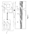
- a detection facility 10 of an entity 20, in this case a person, in a delimited local 30 is described with reference to the figure 1 .
- Such an installation comprises means 40 for detecting the presence of the person in at least two areas of observation of the room, respectively Z1 and Z2, which are chosen so as to overlap at least partially.
- the observation zone Z1 is constituted by the entire volume of the room and the observation zone Z2 by a "slice" of this volume, delimited by two substantially horizontal planes.
- the choice of observation areas of the figure 1 is given for illustrative purposes only and depends in reality, as will be seen in more detail later with the support of specific examples, the type of application that is intended for the detection facility.
- a common feature shared by the detection device according to the invention whatever the application for which it is intended, is based on the use of at least two partially overlapping observation zones (or not disjoint) .
- presence detection means means adapted to detect both a moving entity that immobile. We shall come back in more detail later on the constitution of such means.
- the information collected by the presence detection means for each of the considered observation zones of the local namely presence information and / or movement information of the person in each of these areas, are then provided to the means of detection.
- processing 50 adapted to perform logical operations on this information and which will be discussed in more detail later with reference to the specific examples provided.
- the installation according to the invention further comprises decision means 60, connected to the processing means 50, which, as a function of the logic signal produced by the latter, will make it possible to control a predetermined specific action, such as triggering an alarm, for example .
- One of the essential elements of the detection installation according to the invention is the use of non-disjoint observation zones, associated with the use of presence detection means in each of them, capable of detecting a person, even immobile within each zone. It is then the agreement, determined by the processing means, between the presence information, possibly combined with motion information, collected for each of the non-disjoint observation areas, with those of a logical table, pre-established according to the intended application, which triggers a specific action.
- the presence detection means 40 are preferably based on a use of directional or sectoral wave radiation, as well as on the wave reflection on the person, objects and walls. premises, to establish the presence and location of any person, or part of a person, or object, even immobile in a room.
- the detection means may for example be based on the use of electromagnetic waves, for example of radio, infrared or optical type, or on the use of acoustic waves.
- the detection means 40 comprise a radiofrequency transmission / reception device 41, specific to each selected observation zone, using the principle of radiofrequency radiation and reflection of electromagnetic waves on different objects possibly present in the associated observation zone, as well as on a person present in this zone.
- a signal transmission / reception device 41 is designed from various commercially available radio frequency components for various short-range telecommunication applications and, in particular, scientific and medical and / or short-range industrial applications called ISM / SRD (for Industrial Scientific Medical / Short Range Devices).
- ISM / SRD Industrial Scientific Medical / Short Range Devices
- the signal transmission / reception device 41 is conventionally based on a homodyne structure known per se.
- An example of the radiofrequency components present in such a homodyne circuit is given with reference to the figure 2 .
- the signal transmission / reception device 41 of the figure 2 is composed in particular of one or more transmission elements 44 able to emit signals in the associated observation zone and one or more receiving elements 45 able to collect reflected signals from this observation zone.
- the transmission element 44 of the device 41 consists of one or more antenna systems radiating successively or at the same time in the associated observation zone and which can be placed according to predefined locations in the observation zone.
- These antenna systems may for example consist of radiating coaxial cables, or slot or wire antenna.
- the receiving element 45 of the device 41 may consist of one or more radiofrequency sensors distributed in the associated observation zone and collecting the signals which are reflected from this zone.
- the collected echo is transmitted via a high-gain, low-noise amplifier 451 to a demodulation circuit 452 for the extraction of a modulation from the modulator 453 of the carrier wave and recover the orthogonal I and Q components of the signal, which are each transmitted to an analog / digital converter 455, via a low frequency amplification and filter block, respectively 456 and 457.
- An analog / digital converter 455 is then able to convert the collected analog signals into digital data, in order to perform digital processing on these data.
- these treatments are intended to measure either amplitude variations, or phase variations, or amplitude and phase variations, induced by the presence, even immobile, of the person in the antenna beam .
- the detection means 40 comprise storage means 42 adapted to store a reference echo for each zone observed observation, which is measured for example during an initialization phase of the installation and possibly updated periodically, which reference echo is representative of the signals reflected from the area in question in the absence of the person.
- the principle of presence detection is based on a variation of the echo collected at a time t for the observation zone considered, henceforth called instant echo, with respect to that reflected by said zone in the absence of the person, says reference echo.
- the periodic updating of this reference echo makes it possible moreover to take into account, at regular intervals, possible modifications of this echo brought by physical modifications of the contents of the observation zone concerned, related for example to any input, removal or removal of furniture in the area in question.
- the measurement of the reference echoes for each observation zone can be carried out in several ways, according to one or any combination of the methods described below.
- the detection device measures for a given observation zone, the amplitude, or the phase, or the amplitude and the phase of the signal reflected by said zone, either at the start of operation. the installation in a room deemed empty, either whenever information outside the device indicates that the room is empty.
- the reference echo thus obtained for each observation zone is stored in the storage means of the device provided for this purpose.
- the measurement of the reference echo for a given observation zone, representative of the signals reflected in said zone in the absence of the person, results from a treatment applied. at a plurality of instantaneous echoes collected in the presence of the mobile person in the premises.
- a method consists of estimating the reference echo by successive measurement sequences of the signal received in the presence of the mobile person in the room (instantaneous echo ) and by calculating the average value of the amplitude of these signals, this average value then being taken as the reference value.
- a variant adapted to the case of detection devices capable of measuring the amplitude and the phase of the reflected signal consists in estimating the reference echo by successive measurement sequences of the signal received in the presence of the mobile person in the room (echo instantaneous) by calculating the average value of the complex signal measured during phases of rapid and strong variations of the signal corresponding to movements of the person in the room.
- the detection means After measuring the reference echo for a given observation zone and measuring the instantaneous echo for this same zone, the detection means are able to process these data collected by each pair of antenna 44/45 associated with each observation area.
- the detection means comprise means 43 for comparing the instantaneous echo and the reference echo collected for each observation zone, making it possible to output a presence information and / or, as the case may be, a movement information of the person in each of the considered observation areas of the local.
- These comparison means are typically implemented by a calculator, whose main processing steps will be described in more detail later with reference to the application examples provided.
- the invention will now be described in the context of a specific application relating to the detection of emergency situations, characterized by a fall, a malaise or a loss of consciousness immobilizing a single person on the ground in a room.
- the figure 3 illustrates by way of example an environment of the person 20 to be monitored having a defined space 30, constituted by a room, equipped with the detection device of the invention as just described, and in which are objects 31 and 32, constituted for example by furniture (furniture, lighting or other).
- a first observation zone Z1 (zone 1) illustrated in FIG. figure 3 is defined substantially by the whole of the local.
- a transmitting / receiving device is therefore associated with this first observation zone Z1 with the aim of observing the whole of the room and making it possible to carry out the presence detection of a person throughout the room.
- a first pair of antennas 34 are used as transmit and receive elements advantageously having a very broad radiation pattern (at least 90 ° of aperture in each plane). They may for example be constituted by dipole type antennas in the case of use of radiofrequency waves. They can be arranged either on the ceiling of the room, aiming down the whole room (at least 120 ° of opening in each plane), as illustrated in the example of the figure 3 or, alternatively, close to a wall / ceiling connection (at least 90 ° of opening in each plane).
- a second observation zone Z2 (zone 2), partially covering the first observation zone Z1, is defined by a volume of the room, delimited by the walls thereof and located between two horizontal planes, preferably placed respectively at about 0.8 m and 1.5 m from the floor of the room.
- a transmitting / receiving device is therefore associated with this second observation zone Z2 with the aim of observing this particular zone and making it possible to detect the presence of a person therein.
- a second pair of antennas 33 are used, as transmit and receive elements, advantageously having a broad radiation pattern (from 90 ° to 180 ° of opening in a plane perpendicular to the axis antennas).
- This pair of antenna, associated with the observation zone Z2 may for example be constituted either by a pair of coaxial slot cables, or a pair of slot antenna. It can be arranged, either in the middle of one of the walls of the room, or in a corner of the room. In both cases, these antennas will preferably be placed at an average height of about 1.20 m.
- the measurement of the reference echo in each zone Z1 and Z2 will be performed first of all at the start of the device, during an initialization phase initiated by the installer. Then, the measurement of the reference echoes will be carried out for updating, according to the principles already explained above.
- Each transmission / reception device is designed to measure, at regular intervals, for example every 30 seconds or every minute, the amplitude, or the phase, or the amplitude and the phase of the signal reflected from the associated observation area, thus forming the instantaneous echo.
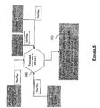
- the figure 4 then illustrates the main processing steps performed by the computer on the data collected by each transmitting / receiving device associated with each observation zone i.
- a processing step 430 consisting of comparing these echoes for the zone is carried out. i considered.
- This comparison between the reference echo and the instantaneous echo may consist in performing a subtraction operation between the amplitude, or the phase, or the amplitude and the phase of said echoes, depending on the type of measurement performed to obtain the echoes .
- a step 431 for limiting the spatial analysis domain is optionally implemented over the range of between 0 and 5 m from the antenna, the maximum detection distance being carried in this particular application to about 5 m.
- a step 433 for analyzing the subtracted echo resulting from the comparison between the reference echo and the instantaneous echo makes it possible to obtain information on the presence or absence of a person in zone i. considered. Indeed, the presence of a mobile or immobile person in the observation zone i considered modifies the subtracted echo, which makes it possible to trigger a detection, to output the presence information Ip of the person in the zone i considered.
- a subtracted echo analysis step 432 may furthermore be implemented in order to obtain information on the movement or absence of movement (immobility) of the person in the zone i considered. Indeed, the presence of a phase modulation or amplitude of the echo subtracted at frequencies of a few Hertz makes it possible to detect the existence of movement of the person present in the zone i considered (by application of the effect Doppler). In this way, the information Im of movement of the person in the zone i considered is obtained.
- the presence and motion information collected in each of the observation zones Z1 and Z2 are then subjected to the processing means 50 to be merged by means of logical operations performed on them.
- the figure 5 illustrates for this purpose a treatment 500 performed by the processing means on the presence and movement information of the person in each of the two observation zones Z1 and Z2, in order to determine an action to be taken according to the result of the execution of logical operations.
- Such a result means that the person is immobile on the ground, then causing the control by the decision means of a specific action that may for example to trigger an alert to a remote rescue center.
- Table 1 below lists all the situations that can be identified by the fusion of the presence and movement information from the two observation zones Z1 and Z2.
- This table in the form of a truth table, includes a first output relating to conclusions emitted according to each of the combinations of the possible values of the operands that are in this case the presence and movement information respectively collected in the observation zones Z1 and Z2 of the local.
- a second output determines actions that can be undertaken, associated with these conclusions.
- Binary states 0 and 1 represent non-detection and detection respectively.
- Case No. (binary code) Z1 Presence Z1 movement Z2 Presence Z2 Movement Conclusion Action 0 (0000) No No No No No one is present in the room Possibility to measure the reference echoes of zones Z1 and Z2 1 (0001) No No No Yes Dysfunctioning detection means in zone Z1.
- the person is moving in zone Z2, so she is standing or sitting Transmitting the failure information of the detection means in zone Z1 2 (0010) No No Yes No Dysfunctioning detection means in zone Z1.
- the person is present and motionless in zone Z2, so she is standing or sitting Transmitting the failure information of the detection means in zone Z1 3 (0011) No No Yes Yes Dysfunctioning detection means in zone Z1.
- the person is present and moving in zone Z2, so she is standing or sitting Transmitting the failure information of the detection means in zone Z1 4 (0100) No Yes No No The person is detected moving in zone Z1 but not present in zone Z2. The person is lying down or down. She is moving. Possible recording of the date and time of the beginning of this situation. Possible increase of the frequency of observation. 5 (0101) No Yes No Yes The person is detected moving in zones Z1 and Z2 nothingness 6 (0110) No Yes Yes No The person is detected moving in zone Z1 and present in zone Z2 without movement.
- the detection installation according to the invention thus makes it possible to obtain a great refinement of the different identifiable situations.
- the detection installation according to the invention advantageously has a self-diagnosis function, allowing identification and treatment of failures and malfunctions.
- cases 1 to 3, 9 and 11 typically correspond to such events, since the overlap between the information collected for each zone Z1 and Z2 corresponds to a physical impossibility. For example, for cases 1 to 3, presence and / or movement is detected in zone Z2, while no presence or movement is detected in zone Z1, thus clearly indicating a malfunction.
- This other specific application relates to management of a safety device such as an airbag, or more commonly called airbag, in a passenger compartment of a motor vehicle.
- a safety device such as an airbag, or more commonly called airbag
- a motor vehicle usually includes a driver's seat and a front passenger seat. It also includes at least one airbag provided for each seat to protect the vehicle users during a collision and thus prevent them from violently striking some equipment of the vehicle.
- a firing of the front airbag during an impact can cause injury or trauma, or even death, especially if the user is in an unusual position, for example having his head down for pick up an object fallen to the ground or in the case where the driver is very close to the steering wheel.
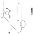
- FIG. 6 An example of this application is shown on the figure 6 wherein a motor vehicle 70 is schematically shown in side view.
- This application requires defining three non-disjoint observation zones.
- a first zone of observation, called zone 1, of the defined space, constituted by the passenger compartment of the motor vehicle, comprises a volume situated between two vertical planes perpendicular to a direction XX 'symbolizing the direction of advance of the vehicle relative to to the road.
- a transmitting / receiving device associated with this first observation zone, comprises a first pair of antennas 71 making it possible to monitor the particular volume constituted by this first observation zone.
- the pair of antennas may consist of either a pair of slotted coaxial cables, or a pair of slit guide type antennas, or a pair of wire antennas. These types of antennas are designed to radiate in their immediate proximity (a few antenna lengths) a field limited spatially to their physical length in all the planes containing their axis. They are further provided to be provided with side shields to limit their radiation in a plane perpendicular to their axis.
- the first pair of antennas 71 may advantageously be positioned in the roof of the vehicle 70 horizontally and parallel to the axis XX 'for monitor the volume constituted by the first observation zone.
- a second predetermined observation zone of the delimited local area constituted by the passenger compartment of the motor vehicle, called zone 2 comprises a volume located between two horizontal planes parallel to the direction XX '.
- a transmitting / receiving device, associated with this second observation zone, comprises a second pair of antennas 72, making it possible to monitor the particular volume constituted by this second observation zone.
- the second pair of antennas 72 has exactly the same characteristics as those mentioned above with reference to the first pair and may advantageously be positioned for example in a lateral upright behind a front door perpendicular to the axis XX '.
- a third predetermined observation zone of the delimited locality constituted by the passenger compartment of the motor vehicle, called zone 3, comprises a volume located between two vertical planes parallel to the direction XX '.
- a transmitting / receiving device, associated with this third observation zone, comprises a third pair of antennas 73, also having the aforementioned characteristics and making it possible to monitor the particular volume constituted by this third observation zone.
- This third pair of antennas may for example be positioned at the junction between the windshield and the roof of the vehicle transversely to the direction XX '.
- Each pair of antennas thus monitors an observation zone of its own, defined by a particular volume of the passenger compartment of the vehicle.
- the head 75 of the user must be located in these three observation zones simultaneously, to allow the triggering of the airbag if necessary, otherwise the airbag is not triggered.
- the measurement of the reference echo in each zone will be carried out, either during the unlocking operation of the vehicle doors, before the driver enters the vehicle, periodically, during the period of non-use of the vehicle.
- each transmission / reception device is designed to measure, at regular intervals, the amplitude, or the phase, or the amplitude and the phase of the reflected signal coming from of the associated observation area, thus forming the instantaneous echo.
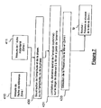
- the figure 7 then illustrates the main processing steps performed by the computer on the data collected by each transmitting / receiving device associated with each observation zone i.
- the same steps as those already described with reference to the figure 4 are implemented, with the only difference that, according to this application, the detection means incorporated in the motor vehicle are adapted to collect only Ip information of presence / absence of the head in each of the three observation zones considered, the movement information not needed.
- the presence / absence information of the head collected in each of the three observation zones are then subjected to the processing means 50 to be merged in a step 500, implementing the logical AND operation as illustrated in FIG. figure 8 , to authorize or prohibit the release of the airbag.
- the detection installation can be applied, according to another example not forming part of the invention, the location and tracking of people in a room.
- observation zones respectively ZYj and ZXi, are divided into first and second transverse series of successive volumes of the room, each of the volumes of the first and second series of volumes being delimited by walls of the premises and located between two substantially vertical planes.
- the different observation zones ZYj of the first series form successive vertical "slices" of the volume of the room and the different observation zones ZXi of the second series also form successive vertical "slices" of the volume of the room, but transverse to the slices ZYj. In this way, the entire volume of the room can be monitored.
- each observation zone thus defined is associated with a transmission / reception device comprising a pair of antennas, respectively PAYj, PAXi, making it possible to monitor the particular volume constituted by the zone d considered observation.
- Each pair of antennas can then be of the same type as that already described with reference to the aforementioned application for detecting the nominal position of the driver's head before an airbag is triggered, and will be arranged along two of the four walls of the premises, as shown in figure 9 , so as to cover the entire surface of the room, the radiation pattern between two pairs of neighboring antennas, for example PAXi and PAX (i + 1) may overlap partially.
- the measurement of the reference echoes of the zones ZYj and ZXi will be carried out first of all at the start of the installation, during an initialization phase executed in the absence of the person to be followed. (or object), or during periods of displacement of the person by implementing the principles already explained above.
- each transmission / reception device is designed to measure, at regular intervals, the amplitude, or the phase, or the amplitude and the phase of the reflected signal coming from of the associated observation area, thus forming the instantaneous echo.
- This information in each of the observation zones is then submitted to the processing means to be merged.
- the treatments performed can then allow, by cross-checking information from the observation areas, to precisely locate a person inside the room.
- a person By way of example, it will be possible for example to locate a person at the intersection of an observation zone ZYj and an observation zone ZXi.
Landscapes
- Engineering & Computer Science (AREA)
- Radar, Positioning & Navigation (AREA)
- Remote Sensing (AREA)
- Physics & Mathematics (AREA)
- General Physics & Mathematics (AREA)
- Computer Networks & Wireless Communication (AREA)
- Business, Economics & Management (AREA)
- Emergency Management (AREA)
- Radar Systems Or Details Thereof (AREA)
- Geophysics And Detection Of Objects (AREA)
Claims (8)
- Anlage (10) zum Erfassen der Position einer beweglichen oder unbeweglichen Entität (20) in einem begrenzten Raum (30), umfassend:- Mittel (40) zum Erfassen der Anwesenheit der Entität in mindestens zwei Beobachtungszonen (Z1, Z2) des Raums, die sich mindestens teilweise überlappen, wobei die Mittel geeignet sind, um mindestens eine Anwesenheitsinformation (Ip) von dieser Entität unabhängig von ihrer Bewegung und eine Bewegungsinformation (Im) der Entität in jeder der Beobachtungszonen zu sammeln,- Verarbeitungsmittel (50), die geeignet sind, über logische Operationen die Anwesenheitsinformation (Ip) und die Bewegungsinformation (Im) der Entität, die für jede der Beobachtungszonen gesammelt sind, zu verschmelzen,- Entscheidungsmittel (60), die mit den Verarbeitungsmitteln verbunden sind und geeignet sind, eine Aktion in Abhängigkeit von einem logischen Signal, das durch die Verarbeitungsmittel erzeugt ist, zu steuern,wobei die Mittel zum Erfassen der Anwesenheit aufweisen:- eine Vorrichtung zum Senden/Empfangen von Signalen (41), die für jede Beobachtungszone eigen ist, die mindestens ein Sendeelement zum Senden von Signalen in der zugehörigen Beobachtungszone und mindestens ein Empfangselement aufweist, um ein unmittelbares Echo zu erfassen, das durch die reflektierten Signale gebildet ist, die von der Beobachtungszone kommen,- Mittel zum Speichern (42) eines Referenzechos für jede Beobachtungszone, das für die reflektierten Signale, die von jeder der Zonen in Abwesenheit der Entität kommen, repräsentativ ist,- Mittel zum Vergleichen (43) des unmittelbaren Echos und des Referenzechos für jede Beobachtungszone, die geeignet sind, die Amplituden- und Phasenschwankungen zwischen den Echos derart zu messen, um die Anwesenheits- und Bewegungsinformationen der Entität in der Beobachtungszone zu erzeugen,wobei die Anlage dadurch gekennzeichnet ist, dass
die Vorrichtung zum Senden/Empfangen eine Hochfrequenz-Sende-/Empfangsschaltung aufweist, umfassend einen Hochfrequenzsignalgenerator, der mit mindestens einem Antennensystem verbunden ist, das das Sendeelement zum Senden der Signale bildet, und mindestens einen Hochfrequenzsensor, der das Empfangselement bildet, das über einen Verstärker und einen Niederfrequenzfilter mit einem Analog-Digital-Wandler verbunden ist, und dadurch, dass
die erste Beobachtungszone (Z1) dem Gesamtvolumen des Raumes entspricht und dass die zweite Beobachtungszone (Z2) in einem Volumen des Raums enthalten ist, das durch Wände des Raums begrenzt ist und sich zwischen zwei im Wesentlichen horizontalen Ebenen befindet, derart, dass die zweite Beobachtungszone (Z2) die erste Beobachtungszone (Z1) teilweise bedeckt. - Anlage nach Anspruch 1, dadurch gekennzeichnet, dass die Mittel zum Vergleichen geeignet sind, eine Subtraktionsoperation zwischen der Amplitude und der Phase der Echos durchzuführen.
- Anlage nach Anspruch 2, dadurch gekennzeichnet, dass die im Wesentlichen horizontalen Ebenen jeweils etwa 0,8 m und 1,5 m vom Boden des Raumes angeordnet sind.
- Anwendung einer Anlage zum Erfassen nach den Ansprüchen 1 bis 3 zum Erkennen einer Notfallsituation in einer Räumlichkeit, die den Raum für die Personenbetreuung zu Hause bildet.
- Verfahren zum Erfassen einer beweglichen oder unbeweglichen Entität (20) in einem begrenzten Raum (30), dadurch gekennzeichnet, dass es die folgenden Schritte aufweist, die darin bestehen:- die Anwesenheit der Entität in mindestens zwei Beobachtungszonen (Z1, Z2) des Raums zu erfassen (432, 433), die sich mindestens teilweise überlappen, derart, um mindestens eine Anwesenheitsinformation (Ip) der Entität unabhängig von ihrer Bewegung und eine Bewegungsinformation (Im) der Entität in jeder der Beobachtungszonen zu sammeln;- über logische Operationen die Anwesenheitsinformation (Ip) und die Bewegungsinformation (Im) der Entität, die für jede der Beobachtungszonen gesammelt sind, derart zu verschmelzen (500), um ein logisches Ergebnissignal erzeugen;- das logische Signal derart zu analysieren (510), um eine Aktion in Abhängigkeit von dem Ergebnis zu steuern,wobei der Schritt des Erfassens der Anwesenheit ferner für jede betreffende Beobachtungszone aufweist:- das Messen (410) und das Speichern eines Referenzechos, das für reflektierte Signale in der Zone in Abwesenheit der Entität repräsentativ ist;- das Messen (411) eines unmittelbaren Echos, das aus den reflektierten Signalen gebildet ist, die von der Beobachtungszone kommen;- das Vergleichen (430) des unmittelbaren Echos mit dem Referenzecho für jede Zone, das darin besteht, Amplituden- und Phasenschwankungen zwischen den Echos derart zu messen, um die Anwesenheits- und Bewegungsinformation der Entität in der Beobachtungszone zu erzeugen,dadurch gekennzeichnet, dass die reflektierten Signale Hochfrequenzsignale sind, die von einem Hochfrequenzsignalgenerator gesendet werden, der mit mindestens einem Antennensystem verbunden ist, und dadurch, dass die erste Beobachtungszone (Z1) dem Gesamtvolumen des Raumes entspricht und dass die zweite Beobachtungszone (Z2) in einem Volumen des Raums enthalten ist, das durch Wände des Raums begrenzt ist und sich zwischen zwei im Wesentlichen horizontalen Ebenen befindet, derart, dass die zweite Beobachtungszone (Z2) die erste Beobachtungszone (Z1) teilweise bedeckt.
- Verfahren nach Anspruch 5, dadurch gekennzeichnet, dass der Schritt zum Vergleichen (430) des unmittelbaren Echos mit dem Referenzecho durch eine Subtraktionsoperation zwischen der Amplitude und der Phase der Echos durchgeführt wird.
- Verfahren nach einem der Ansprüche 5 bis 6, dadurch gekennzeichnet, dass das Messen (410) des Referenzechos, das für die reflektierten Signale in der Zone in Abwesenheit der Entität repräsentativ ist, durchgeführt wird, wenn der Raum leer ist.
- Verfahren nach einem der Ansprüche 5 bis 7, dadurch gekennzeichnet, dass das Messen (410) des Referenzechos, das für die reflektierten Signale in der Zone in Abwesenheit der Entität repräsentativ ist, aus einer Verarbeitung hervorgeht, die auf mehrere unmittelbare Echos angewendet wird, die in Anwesenheit der mobilen Entität in dem Raum gesammelt werden.
Applications Claiming Priority (2)
| Application Number | Priority Date | Filing Date | Title |
|---|---|---|---|
| FR0760143A FR2925737B1 (fr) | 2007-12-20 | 2007-12-20 | Installation de detection de personnes dans un espace delimite. |
| PCT/FR2008/052309 WO2009081018A1 (fr) | 2007-12-20 | 2008-12-16 | Installation de detection de personnes dans un espace delimite |
Publications (2)
| Publication Number | Publication Date |
|---|---|
| EP2232298A1 EP2232298A1 (de) | 2010-09-29 |
| EP2232298B1 true EP2232298B1 (de) | 2018-11-21 |
Family
ID=39643916
Family Applications (1)
| Application Number | Title | Priority Date | Filing Date |
|---|---|---|---|
| EP08865648.3A Active EP2232298B1 (de) | 2007-12-20 | 2008-12-16 | Ausrüstung zur erfassung von personen in einem abgegrenzten raum |
Country Status (5)
| Country | Link |
|---|---|
| US (1) | US8593279B2 (de) |
| EP (1) | EP2232298B1 (de) |
| DK (1) | DK2232298T3 (de) |
| FR (1) | FR2925737B1 (de) |
| WO (1) | WO2009081018A1 (de) |
Families Citing this family (21)
| Publication number | Priority date | Publication date | Assignee | Title |
|---|---|---|---|---|
| FR2910161B1 (fr) * | 2006-12-15 | 2009-01-30 | Thales Sa | Systeme goniometrique de mini capteurs doppler en reseaux pour la surveillance de perimetres |
| JP5718139B2 (ja) * | 2011-04-21 | 2015-05-13 | 日野自動車株式会社 | レーダ装置、バス、および乗客移動検出方法、並びにプログラム |
| WO2013014578A1 (en) * | 2011-07-26 | 2013-01-31 | Koninklijke Philips Electronics N.V. | Monitoring system and method for monitoring a monitored area |
| US8842495B2 (en) * | 2011-09-23 | 2014-09-23 | Rethink Robotics, Inc. | Ultrasonic motion detection |
| FI123399B (fi) * | 2012-04-04 | 2013-03-28 | Seniortek Oy | Valvontajärjestelmä |
| US9283677B2 (en) | 2012-04-05 | 2016-03-15 | Rethink Robotics, Inc. | Visual indication of target tracking |
| WO2014173724A1 (en) * | 2013-04-26 | 2014-10-30 | Koninklijke Philips N.V. | Sensing within a region |
| EP2808693B1 (de) * | 2013-05-27 | 2019-08-14 | Volvo Car Corporation | Verfahren und System zur Ortsbestimmung eines Lebewesens in einem Fahrzeug |
| JP6447915B2 (ja) * | 2015-03-13 | 2019-01-09 | パナソニックIpマネジメント株式会社 | 負荷制御装置 |
| FI20150126A (fi) * | 2015-04-20 | 2016-10-21 | Viasec Oy | Järjestelmä ja menetelmä henkilön valvomiseksi rakennuksessa tai rakennuksissa |
| US20200279465A1 (en) * | 2015-12-02 | 2020-09-03 | Kimberly A. GAVIN | System and method for wearable technology |
| CA3011775A1 (en) | 2016-01-20 | 2017-07-27 | Koninklijke Philips N.V. | Occupancy sensing system and sensing method |
| US9733356B1 (en) | 2016-02-17 | 2017-08-15 | Secure Bubble Ltd | Detection of animate presence with an ultrasonic signal |
| JP6799826B2 (ja) * | 2017-03-22 | 2020-12-16 | パナソニックIpマネジメント株式会社 | 画像生成装置、画像生成方法、プログラム及びそれを記録した記録媒体 |
| US11520028B2 (en) * | 2018-01-10 | 2022-12-06 | Richwave Technology Corp. | Occupancy detection using multiple antenna motion sensing |
| US11662450B2 (en) * | 2018-08-24 | 2023-05-30 | Lutron Technology Company Llc | Occupant detection device |
| TWI818078B (zh) * | 2018-09-18 | 2023-10-11 | 美商塔切爾實驗室公司 | 感測系統及識別人或物件之方法 |
| ES2959018T3 (es) * | 2019-11-15 | 2024-02-19 | Signify Holding Bv | Cambio de las características de transmisión y/o recepción para detectar eventos distintos a la presencia humana |
| US11373508B2 (en) * | 2020-01-30 | 2022-06-28 | The Boeing Company | Computer-implemented methods and system for monitoring personnel activity using non-motion sensors |
| IT202100025829A1 (it) * | 2021-10-08 | 2023-04-08 | Inxpect S P A | Sistema radar per controllare accessi ad un ambiente |
| US12290365B1 (en) * | 2024-06-06 | 2025-05-06 | Triton Sensors, Llc | Health and safety monitoring and alert system and method |
Family Cites Families (15)
| Publication number | Priority date | Publication date | Assignee | Title |
|---|---|---|---|---|
| GB1548771A (en) * | 1976-11-05 | 1979-07-18 | Spirig Ernst | Intruder alarm systems |
| US4527151A (en) * | 1982-05-03 | 1985-07-02 | Sri International | Method and apparatus for intrusion detection |
| JPS60152904A (ja) * | 1984-01-20 | 1985-08-12 | Nippon Denso Co Ltd | 車両運転者位置認識装置 |
| GB9206360D0 (en) * | 1992-03-24 | 1992-05-06 | Rover Group | A device for and a method of surveillance of a space |
| US6784379B2 (en) * | 1995-06-07 | 2004-08-31 | Automotive Technologies International, Inc. | Arrangement for obtaining information about an occupying item of a seat |
| US5491467A (en) | 1994-01-31 | 1996-02-13 | C & K Systems, Inc. | Location independent intrusion detection system |
| US5905436A (en) * | 1996-10-24 | 1999-05-18 | Gerontological Solutions, Inc. | Situation-based monitoring system |
| JP3005496B2 (ja) * | 1997-05-21 | 2000-01-31 | 日本電気株式会社 | 送信規制装置及び無線送受信端末装置並びにこれ等を用いた送信規制システム |
| WO1999027335A1 (en) * | 1997-11-25 | 1999-06-03 | Boards Of Regents, The University Of Texas System | Object presence detection using dual wavelength bands |
| DE19926845A1 (de) * | 1999-04-09 | 2000-10-19 | Steinel Gmbh & Co Kg | Sicherheitsvorrichtung und Verfahren zum Betreiben einer Sicherheitsvorrichtung |
| US6323773B1 (en) * | 2000-06-16 | 2001-11-27 | Battelle Memorial Institute | Alerting device and method for reminding a person of a risk |
| JP2002250607A (ja) * | 2001-02-27 | 2002-09-06 | Optex Co Ltd | 物体検知センサ |
| AU2002357801A1 (en) * | 2001-12-11 | 2003-07-09 | B.E.A. Holdings, Inc. | Unitary trifunctional door manager and method |
| US7047132B2 (en) * | 2004-01-12 | 2006-05-16 | Steven Jacobs | Mobile vehicle sensor array |
| US7126477B2 (en) * | 2004-01-15 | 2006-10-24 | Raytheon Company | Millimeter-wave area-protection system and method |
-
2007
- 2007-12-20 FR FR0760143A patent/FR2925737B1/fr active Active
-
2008
- 2008-12-16 WO PCT/FR2008/052309 patent/WO2009081018A1/fr not_active Ceased
- 2008-12-16 DK DK08865648.3T patent/DK2232298T3/en active
- 2008-12-16 EP EP08865648.3A patent/EP2232298B1/de active Active
- 2008-12-16 US US12/817,942 patent/US8593279B2/en not_active Expired - Fee Related
Non-Patent Citations (1)
| Title |
|---|
| None * |
Also Published As
| Publication number | Publication date |
|---|---|
| FR2925737B1 (fr) | 2015-01-23 |
| EP2232298A1 (de) | 2010-09-29 |
| FR2925737A1 (fr) | 2009-06-26 |
| DK2232298T3 (en) | 2019-02-04 |
| US20100321184A1 (en) | 2010-12-23 |
| WO2009081018A1 (fr) | 2009-07-02 |
| US8593279B2 (en) | 2013-11-26 |
| WO2009081018A4 (fr) | 2009-09-24 |
Similar Documents
| Publication | Publication Date | Title |
|---|---|---|
| EP2232298B1 (de) | Ausrüstung zur erfassung von personen in einem abgegrenzten raum | |
| EP3227705B1 (de) | Elektronische vorrichtung zur nähenortung eines terrestrischen objekts und verfahren zum orten solch eines objekts | |
| FR2911987A1 (fr) | Procede de surveillance de personnes autorisees et non autorisees dans un perimetre de securite autour d'un appareil | |
| SE1650327A1 (en) | Method and system for theft detection in a vehicle | |
| EP2123060A1 (de) | Elektromechanisches bestimmen der kompromittierung eines gehäuses | |
| US6337625B1 (en) | Intrusion detection process and device | |
| FR3052902A1 (fr) | Capteur d'alarme, systeme comprenant un tel capteur, et procede d'utilisation de ce systeme d'alarme | |
| EP3020220B1 (de) | Vorrichtung und verfahren zur steuerung des zugriffs auf mindestens eine maschine | |
| FR2700625A1 (fr) | Procédé de verrouillage d'un véhicule commandé par un signal radio et dispositif de mise en Óoeuvre. | |
| EP3814807B1 (de) | Tragbares detektionssystem mit magnetostatischen sensoren | |
| US20190346379A1 (en) | X-ray screening system and method | |
| FR2974933A1 (fr) | Systeme pour detecter une intrusion et procede | |
| CA2771758C (en) | Method and system for on-board vehicle detection of harmful material | |
| WO2007028827A1 (fr) | Procede et systeme de localisation d'individus a l'interieur d'un batiment | |
| FR2960066A1 (fr) | Procede et dispositif de signalisation d'un obstacle potentiel, tel qu'un pieton, a destination d'un conducteur de vehicule, notamment d'un conducteur d'engin. | |
| FR2632104A1 (fr) | Procede de surveillance d'emplacements affectes au depot d'objets et dispositif pour sa mise en oeuvre | |
| WO2023110357A1 (fr) | Procede de detection de presence a l'interieur d'un vehicule verrouille et dispositif de detection associe | |
| FR3117966A1 (fr) | Système de détection d’intrusion pour un véhicule et véhicule et procédé associés | |
| FR3134773A1 (fr) | Procede de scrutation de presence a l’interieur d’un vehicule verrouille, dispositif et systeme de scrutation associes | |
| CA3043715A1 (en) | Systems and methods to deter theft of commercial products | |
| FR2807843A1 (fr) | Perfectionnements a la detection de la presence d'une personne ou d'un animal dans un coffre de vehicule automobile | |
| FR2812433A1 (fr) | Procede et dispositif pour la protection en continu contre les intrusions dans des locaux eventuellement habites | |
| EP0188165B1 (de) | Verfahren und Vorrichtung zum Schutz von Gebäuden gegen Eindringen | |
| FR3094510A1 (fr) | Dispositif de reconnaissance de situation, cabine de passagers d’aeronef et procede de surveillance de cabines de passagers d’aeronef | |
| FR2904506A1 (fr) | Procede et dispositif de transmission d'image dans ou depuis un aeronef et aeronef comportant un tel dipositif |
Legal Events
| Date | Code | Title | Description |
|---|---|---|---|
| PUAI | Public reference made under article 153(3) epc to a published international application that has entered the european phase |
Free format text: ORIGINAL CODE: 0009012 |
|
| 17P | Request for examination filed |
Effective date: 20100624 |
|
| AK | Designated contracting states |
Kind code of ref document: A1 Designated state(s): AT BE BG CH CY CZ DE DK EE ES FI FR GB GR HR HU IE IS IT LI LT LU LV MC MT NL NO PL PT RO SE SI SK TR |
|
| AX | Request for extension of the european patent |
Extension state: AL BA MK RS |
|
| DAX | Request for extension of the european patent (deleted) | ||
| 17Q | First examination report despatched |
Effective date: 20160304 |
|
| RAP1 | Party data changed (applicant data changed or rights of an application transferred) |
Owner name: ISITEK Owner name: ONERA (OFFICE NATIONAL D'ETUDES ET DE RECHERCHES A |
|
| RAP1 | Party data changed (applicant data changed or rights of an application transferred) |
Owner name: ISITEK Owner name: OFFICE NATIONAL D'ETUDES ET DE RECHERCHES AEROSPAT |
|
| STAA | Information on the status of an ep patent application or granted ep patent |
Free format text: STATUS: EXAMINATION IS IN PROGRESS |
|
| REG | Reference to a national code |
Ref country code: DE Ref legal event code: R079 Ref document number: 602008058056 Country of ref document: DE Free format text: PREVIOUS MAIN CLASS: G01S0013870000 Ipc: G01S0013040000 |
|
| GRAP | Despatch of communication of intention to grant a patent |
Free format text: ORIGINAL CODE: EPIDOSNIGR1 |
|
| STAA | Information on the status of an ep patent application or granted ep patent |
Free format text: STATUS: GRANT OF PATENT IS INTENDED |
|
| RIC1 | Information provided on ipc code assigned before grant |
Ipc: G01S 13/04 20060101AFI20180117BHEP Ipc: G08B 21/22 20060101ALI20180117BHEP Ipc: G01S 13/56 20060101ALI20180117BHEP Ipc: G08B 13/187 20060101ALI20180117BHEP Ipc: G01S 13/87 20060101ALI20180117BHEP |
|
| INTG | Intention to grant announced |
Effective date: 20180205 |
|
| GRAS | Grant fee paid |
Free format text: ORIGINAL CODE: EPIDOSNIGR3 |
|
| 19U | Interruption of proceedings before grant |
Effective date: 20140206 |
|
| 19W | Proceedings resumed before grant after interruption of proceedings |
Effective date: 20181001 |
|
| GRAA | (expected) grant |
Free format text: ORIGINAL CODE: 0009210 |
|
| STAA | Information on the status of an ep patent application or granted ep patent |
Free format text: STATUS: THE PATENT HAS BEEN GRANTED |
|
| RAP1 | Party data changed (applicant data changed or rights of an application transferred) |
Owner name: OFFICE NATIONAL D'ETUDES ET DE RECHERCHES AEROSPAT |
|
| AK | Designated contracting states |
Kind code of ref document: B1 Designated state(s): AT BE BG CH CY CZ DE DK EE ES FI FR GB GR HR HU IE IS IT LI LT LU LV MC MT NL NO PL PT RO SE SI SK TR |
|
| REG | Reference to a national code |
Ref country code: CH Ref legal event code: EP |
|
| REG | Reference to a national code |
Ref country code: IE Ref legal event code: FG4D Free format text: LANGUAGE OF EP DOCUMENT: FRENCH |
|
| REG | Reference to a national code |
Ref country code: DE Ref legal event code: R096 Ref document number: 602008058056 Country of ref document: DE |
|
| REG | Reference to a national code |
Ref country code: CH Ref legal event code: NV Representative=s name: NOVAGRAAF INTERNATIONAL SA, CH |
|
| REG | Reference to a national code |
Ref country code: AT Ref legal event code: REF Ref document number: 1068193 Country of ref document: AT Kind code of ref document: T Effective date: 20181215 |
|
| REG | Reference to a national code |
Ref country code: DK Ref legal event code: T3 Effective date: 20190201 |
|
| REG | Reference to a national code |
Ref country code: NL Ref legal event code: FP |
|
| REG | Reference to a national code |
Ref country code: SE Ref legal event code: TRGR |
|
| REG | Reference to a national code |
Ref country code: NO Ref legal event code: T2 Effective date: 20181121 |
|
| PG25 | Lapsed in a contracting state [announced via postgrant information from national office to epo] |
Ref country code: HR Free format text: LAPSE BECAUSE OF FAILURE TO SUBMIT A TRANSLATION OF THE DESCRIPTION OR TO PAY THE FEE WITHIN THE PRESCRIBED TIME-LIMIT Effective date: 20181121 Ref country code: LT Free format text: LAPSE BECAUSE OF FAILURE TO SUBMIT A TRANSLATION OF THE DESCRIPTION OR TO PAY THE FEE WITHIN THE PRESCRIBED TIME-LIMIT Effective date: 20181121 Ref country code: BG Free format text: LAPSE BECAUSE OF FAILURE TO SUBMIT A TRANSLATION OF THE DESCRIPTION OR TO PAY THE FEE WITHIN THE PRESCRIBED TIME-LIMIT Effective date: 20190221 Ref country code: ES Free format text: LAPSE BECAUSE OF FAILURE TO SUBMIT A TRANSLATION OF THE DESCRIPTION OR TO PAY THE FEE WITHIN THE PRESCRIBED TIME-LIMIT Effective date: 20181121 Ref country code: LV Free format text: LAPSE BECAUSE OF FAILURE TO SUBMIT A TRANSLATION OF THE DESCRIPTION OR TO PAY THE FEE WITHIN THE PRESCRIBED TIME-LIMIT Effective date: 20181121 |
|
| PG25 | Lapsed in a contracting state [announced via postgrant information from national office to epo] |
Ref country code: PT Free format text: LAPSE BECAUSE OF FAILURE TO SUBMIT A TRANSLATION OF THE DESCRIPTION OR TO PAY THE FEE WITHIN THE PRESCRIBED TIME-LIMIT Effective date: 20190321 Ref country code: GR Free format text: LAPSE BECAUSE OF FAILURE TO SUBMIT A TRANSLATION OF THE DESCRIPTION OR TO PAY THE FEE WITHIN THE PRESCRIBED TIME-LIMIT Effective date: 20190222 |
|
| PG25 | Lapsed in a contracting state [announced via postgrant information from national office to epo] |
Ref country code: CZ Free format text: LAPSE BECAUSE OF FAILURE TO SUBMIT A TRANSLATION OF THE DESCRIPTION OR TO PAY THE FEE WITHIN THE PRESCRIBED TIME-LIMIT Effective date: 20181121 Ref country code: IT Free format text: LAPSE BECAUSE OF FAILURE TO SUBMIT A TRANSLATION OF THE DESCRIPTION OR TO PAY THE FEE WITHIN THE PRESCRIBED TIME-LIMIT Effective date: 20181121 Ref country code: PL Free format text: LAPSE BECAUSE OF FAILURE TO SUBMIT A TRANSLATION OF THE DESCRIPTION OR TO PAY THE FEE WITHIN THE PRESCRIBED TIME-LIMIT Effective date: 20181121 |
|
| REG | Reference to a national code |
Ref country code: DE Ref legal event code: R097 Ref document number: 602008058056 Country of ref document: DE |
|
| PG25 | Lapsed in a contracting state [announced via postgrant information from national office to epo] |
Ref country code: MC Free format text: LAPSE BECAUSE OF FAILURE TO SUBMIT A TRANSLATION OF THE DESCRIPTION OR TO PAY THE FEE WITHIN THE PRESCRIBED TIME-LIMIT Effective date: 20181121 Ref country code: RO Free format text: LAPSE BECAUSE OF FAILURE TO SUBMIT A TRANSLATION OF THE DESCRIPTION OR TO PAY THE FEE WITHIN THE PRESCRIBED TIME-LIMIT Effective date: 20181121 Ref country code: SK Free format text: LAPSE BECAUSE OF FAILURE TO SUBMIT A TRANSLATION OF THE DESCRIPTION OR TO PAY THE FEE WITHIN THE PRESCRIBED TIME-LIMIT Effective date: 20181121 Ref country code: EE Free format text: LAPSE BECAUSE OF FAILURE TO SUBMIT A TRANSLATION OF THE DESCRIPTION OR TO PAY THE FEE WITHIN THE PRESCRIBED TIME-LIMIT Effective date: 20181121 |
|
| PLBE | No opposition filed within time limit |
Free format text: ORIGINAL CODE: 0009261 |
|
| STAA | Information on the status of an ep patent application or granted ep patent |
Free format text: STATUS: NO OPPOSITION FILED WITHIN TIME LIMIT |
|
| 26N | No opposition filed |
Effective date: 20190822 |
|
| PG25 | Lapsed in a contracting state [announced via postgrant information from national office to epo] |
Ref country code: SI Free format text: LAPSE BECAUSE OF FAILURE TO SUBMIT A TRANSLATION OF THE DESCRIPTION OR TO PAY THE FEE WITHIN THE PRESCRIBED TIME-LIMIT Effective date: 20181121 |
|
| PG25 | Lapsed in a contracting state [announced via postgrant information from national office to epo] |
Ref country code: MT Free format text: LAPSE BECAUSE OF FAILURE TO SUBMIT A TRANSLATION OF THE DESCRIPTION OR TO PAY THE FEE WITHIN THE PRESCRIBED TIME-LIMIT Effective date: 20181121 |
|
| PG25 | Lapsed in a contracting state [announced via postgrant information from national office to epo] |
Ref country code: TR Free format text: LAPSE BECAUSE OF FAILURE TO SUBMIT A TRANSLATION OF THE DESCRIPTION OR TO PAY THE FEE WITHIN THE PRESCRIBED TIME-LIMIT Effective date: 20181121 |
|
| PG25 | Lapsed in a contracting state [announced via postgrant information from national office to epo] |
Ref country code: CY Free format text: LAPSE BECAUSE OF FAILURE TO SUBMIT A TRANSLATION OF THE DESCRIPTION OR TO PAY THE FEE WITHIN THE PRESCRIBED TIME-LIMIT Effective date: 20181121 Ref country code: HU Free format text: LAPSE BECAUSE OF FAILURE TO SUBMIT A TRANSLATION OF THE DESCRIPTION OR TO PAY THE FEE WITHIN THE PRESCRIBED TIME-LIMIT; INVALID AB INITIO Effective date: 20081216 |
|
| REG | Reference to a national code |
Ref country code: AT Ref legal event code: UEP Ref document number: 1068193 Country of ref document: AT Kind code of ref document: T Effective date: 20181121 |
|
| PGFP | Annual fee paid to national office [announced via postgrant information from national office to epo] |
Ref country code: SE Payment date: 20221221 Year of fee payment: 15 Ref country code: NO Payment date: 20221220 Year of fee payment: 15 Ref country code: NL Payment date: 20221222 Year of fee payment: 15 Ref country code: LU Payment date: 20221219 Year of fee payment: 15 Ref country code: IE Payment date: 20221219 Year of fee payment: 15 Ref country code: FI Payment date: 20221216 Year of fee payment: 15 Ref country code: DK Payment date: 20221221 Year of fee payment: 15 Ref country code: AT Payment date: 20221216 Year of fee payment: 15 |
|
| PGFP | Annual fee paid to national office [announced via postgrant information from national office to epo] |
Ref country code: IS Payment date: 20221222 Year of fee payment: 15 Ref country code: BE Payment date: 20221223 Year of fee payment: 15 |
|
| PGFP | Annual fee paid to national office [announced via postgrant information from national office to epo] |
Ref country code: GB Payment date: 20231221 Year of fee payment: 16 |
|
| PGFP | Annual fee paid to national office [announced via postgrant information from national office to epo] |
Ref country code: FR Payment date: 20231221 Year of fee payment: 16 Ref country code: DE Payment date: 20231219 Year of fee payment: 16 |
|
| PGFP | Annual fee paid to national office [announced via postgrant information from national office to epo] |
Ref country code: CH Payment date: 20240101 Year of fee payment: 16 |
|
| REG | Reference to a national code |
Ref country code: DK Ref legal event code: EBP Effective date: 20231231 |
|
| REG | Reference to a national code |
Ref country code: SE Ref legal event code: EUG |
|
| PG25 | Lapsed in a contracting state [announced via postgrant information from national office to epo] |
Ref country code: FI Free format text: LAPSE BECAUSE OF NON-PAYMENT OF DUE FEES Effective date: 20231216 |
|
| REG | Reference to a national code |
Ref country code: NL Ref legal event code: MM Effective date: 20240101 |
|
| REG | Reference to a national code |
Ref country code: AT Ref legal event code: MM01 Ref document number: 1068193 Country of ref document: AT Kind code of ref document: T Effective date: 20231216 |
|
| PG25 | Lapsed in a contracting state [announced via postgrant information from national office to epo] |
Ref country code: LU Free format text: LAPSE BECAUSE OF NON-PAYMENT OF DUE FEES Effective date: 20231216 |
|
| REG | Reference to a national code |
Ref country code: BE Ref legal event code: MM Effective date: 20231231 |
|
| PG25 | Lapsed in a contracting state [announced via postgrant information from national office to epo] |
Ref country code: LU Free format text: LAPSE BECAUSE OF NON-PAYMENT OF DUE FEES Effective date: 20231216 |
|
| PG25 | Lapsed in a contracting state [announced via postgrant information from national office to epo] |
Ref country code: NL Free format text: LAPSE BECAUSE OF NON-PAYMENT OF DUE FEES Effective date: 20240101 |
|
| PG25 | Lapsed in a contracting state [announced via postgrant information from national office to epo] |
Ref country code: NL Free format text: LAPSE BECAUSE OF NON-PAYMENT OF DUE FEES Effective date: 20240101 |
|
| REG | Reference to a national code |
Ref country code: IE Ref legal event code: MM4A |
|
| PG25 | Lapsed in a contracting state [announced via postgrant information from national office to epo] |
Ref country code: IE Free format text: LAPSE BECAUSE OF NON-PAYMENT OF DUE FEES Effective date: 20231216 |
|
| PG25 | Lapsed in a contracting state [announced via postgrant information from national office to epo] |
Ref country code: BE Free format text: LAPSE BECAUSE OF NON-PAYMENT OF DUE FEES Effective date: 20231231 |
|
| PG25 | Lapsed in a contracting state [announced via postgrant information from national office to epo] |
Ref country code: AT Free format text: LAPSE BECAUSE OF NON-PAYMENT OF DUE FEES Effective date: 20231216 |
|
| PG25 | Lapsed in a contracting state [announced via postgrant information from national office to epo] |
Ref country code: NO Free format text: LAPSE BECAUSE OF NON-PAYMENT OF DUE FEES Effective date: 20231231 Ref country code: IE Free format text: LAPSE BECAUSE OF NON-PAYMENT OF DUE FEES Effective date: 20231216 Ref country code: BE Free format text: LAPSE BECAUSE OF NON-PAYMENT OF DUE FEES Effective date: 20231231 Ref country code: AT Free format text: LAPSE BECAUSE OF NON-PAYMENT OF DUE FEES Effective date: 20231216 |
|
| PG25 | Lapsed in a contracting state [announced via postgrant information from national office to epo] |
Ref country code: DK Free format text: LAPSE BECAUSE OF NON-PAYMENT OF DUE FEES Effective date: 20231231 |
|
| PG25 | Lapsed in a contracting state [announced via postgrant information from national office to epo] |
Ref country code: DK Free format text: LAPSE BECAUSE OF NON-PAYMENT OF DUE FEES Effective date: 20231231 |
|
| REG | Reference to a national code |
Ref country code: DE Ref legal event code: R119 Ref document number: 602008058056 Country of ref document: DE |
|
| REG | Reference to a national code |
Ref country code: CH Ref legal event code: PL |
|
| GBPC | Gb: european patent ceased through non-payment of renewal fee |
Effective date: 20241216 |
|
| PG25 | Lapsed in a contracting state [announced via postgrant information from national office to epo] |
Ref country code: DE Free format text: LAPSE BECAUSE OF NON-PAYMENT OF DUE FEES Effective date: 20250701 |
|
| PG25 | Lapsed in a contracting state [announced via postgrant information from national office to epo] |
Ref country code: SE Free format text: LAPSE BECAUSE OF NON-PAYMENT OF DUE FEES Effective date: 20231217 |
|
| PG25 | Lapsed in a contracting state [announced via postgrant information from national office to epo] |
Ref country code: GB Free format text: LAPSE BECAUSE OF NON-PAYMENT OF DUE FEES Effective date: 20241216 Ref country code: IS Free format text: LAPSE BECAUSE OF NON-PAYMENT OF DUE FEES Effective date: 20240701 |
|
| PG25 | Lapsed in a contracting state [announced via postgrant information from national office to epo] |
Ref country code: FR Free format text: LAPSE BECAUSE OF NON-PAYMENT OF DUE FEES Effective date: 20241231 |
|
| PG25 | Lapsed in a contracting state [announced via postgrant information from national office to epo] |
Ref country code: CH Free format text: LAPSE BECAUSE OF NON-PAYMENT OF DUE FEES Effective date: 20241231 |