EP4143531B1 - Führungsgerät und mechanisches system einschliesslich eines solchen geräts - Google Patents
Führungsgerät und mechanisches system einschliesslich eines solchen geräts Download PDFInfo
- Publication number
- EP4143531B1 EP4143531B1 EP21734889.5A EP21734889A EP4143531B1 EP 4143531 B1 EP4143531 B1 EP 4143531B1 EP 21734889 A EP21734889 A EP 21734889A EP 4143531 B1 EP4143531 B1 EP 4143531B1
- Authority
- EP
- European Patent Office
- Prior art keywords
- friction surface
- guide device
- wear
- metal component
- detection system
- Prior art date
- Legal status (The legal status is an assumption and is not a legal conclusion. Google has not performed a legal analysis and makes no representation as to the accuracy of the status listed.)
- Active
Links
Images


Classifications
-
- G—PHYSICS
- G01—MEASURING; TESTING
- G01M—TESTING STATIC OR DYNAMIC BALANCE OF MACHINES OR STRUCTURES; TESTING OF STRUCTURES OR APPARATUS, NOT OTHERWISE PROVIDED FOR
- G01M13/00—Testing of machine parts
- G01M13/02—Gearings; Transmission mechanisms
-
- F—MECHANICAL ENGINEERING; LIGHTING; HEATING; WEAPONS; BLASTING
- F16—ENGINEERING ELEMENTS AND UNITS; GENERAL MEASURES FOR PRODUCING AND MAINTAINING EFFECTIVE FUNCTIONING OF MACHINES OR INSTALLATIONS; THERMAL INSULATION IN GENERAL
- F16C—SHAFTS; FLEXIBLE SHAFTS; ELEMENTS OR CRANKSHAFT MECHANISMS; ROTARY BODIES OTHER THAN GEARING ELEMENTS; BEARINGS
- F16C17/00—Sliding-contact bearings for exclusively rotary movement
- F16C17/02—Sliding-contact bearings for exclusively rotary movement for radial load only
-
- F—MECHANICAL ENGINEERING; LIGHTING; HEATING; WEAPONS; BLASTING
- F16—ENGINEERING ELEMENTS AND UNITS; GENERAL MEASURES FOR PRODUCING AND MAINTAINING EFFECTIVE FUNCTIONING OF MACHINES OR INSTALLATIONS; THERMAL INSULATION IN GENERAL
- F16C—SHAFTS; FLEXIBLE SHAFTS; ELEMENTS OR CRANKSHAFT MECHANISMS; ROTARY BODIES OTHER THAN GEARING ELEMENTS; BEARINGS
- F16C17/00—Sliding-contact bearings for exclusively rotary movement
- F16C17/12—Sliding-contact bearings for exclusively rotary movement characterised by features not related to the direction of the load
- F16C17/24—Sliding-contact bearings for exclusively rotary movement characterised by features not related to the direction of the load with devices affected by abnormal or undesired positions, e.g. for preventing overheating, for safety
- F16C17/246—Sliding-contact bearings for exclusively rotary movement characterised by features not related to the direction of the load with devices affected by abnormal or undesired positions, e.g. for preventing overheating, for safety related to wear, e.g. sensors for measuring wear
-
- F—MECHANICAL ENGINEERING; LIGHTING; HEATING; WEAPONS; BLASTING
- F16—ENGINEERING ELEMENTS AND UNITS; GENERAL MEASURES FOR PRODUCING AND MAINTAINING EFFECTIVE FUNCTIONING OF MACHINES OR INSTALLATIONS; THERMAL INSULATION IN GENERAL
- F16C—SHAFTS; FLEXIBLE SHAFTS; ELEMENTS OR CRANKSHAFT MECHANISMS; ROTARY BODIES OTHER THAN GEARING ELEMENTS; BEARINGS
- F16C33/00—Parts of bearings; Special methods for making bearings or parts thereof
- F16C33/02—Parts of sliding-contact bearings
- F16C33/04—Brasses; Bushes; Linings
- F16C33/06—Sliding surface mainly made of metal
- F16C33/10—Construction relative to lubrication
- F16C33/102—Construction relative to lubrication with grease as lubricant
-
- F—MECHANICAL ENGINEERING; LIGHTING; HEATING; WEAPONS; BLASTING
- F16—ENGINEERING ELEMENTS AND UNITS; GENERAL MEASURES FOR PRODUCING AND MAINTAINING EFFECTIVE FUNCTIONING OF MACHINES OR INSTALLATIONS; THERMAL INSULATION IN GENERAL
- F16C—SHAFTS; FLEXIBLE SHAFTS; ELEMENTS OR CRANKSHAFT MECHANISMS; ROTARY BODIES OTHER THAN GEARING ELEMENTS; BEARINGS
- F16C41/00—Other accessories, e.g. devices integrated in the bearing not relating to the bearing function as such
- F16C41/008—Identification means, e.g. markings, RFID-tags; Data transfer means
-
- F—MECHANICAL ENGINEERING; LIGHTING; HEATING; WEAPONS; BLASTING
- F16—ENGINEERING ELEMENTS AND UNITS; GENERAL MEASURES FOR PRODUCING AND MAINTAINING EFFECTIVE FUNCTIONING OF MACHINES OR INSTALLATIONS; THERMAL INSULATION IN GENERAL
- F16C—SHAFTS; FLEXIBLE SHAFTS; ELEMENTS OR CRANKSHAFT MECHANISMS; ROTARY BODIES OTHER THAN GEARING ELEMENTS; BEARINGS
- F16C43/00—Assembling bearings
- F16C43/02—Assembling sliding-contact bearings
-
- G—PHYSICS
- G01—MEASURING; TESTING
- G01M—TESTING STATIC OR DYNAMIC BALANCE OF MACHINES OR STRUCTURES; TESTING OF STRUCTURES OR APPARATUS, NOT OTHERWISE PROVIDED FOR
- G01M13/00—Testing of machine parts
- G01M13/04—Bearings
-
- F—MECHANICAL ENGINEERING; LIGHTING; HEATING; WEAPONS; BLASTING
- F16—ENGINEERING ELEMENTS AND UNITS; GENERAL MEASURES FOR PRODUCING AND MAINTAINING EFFECTIVE FUNCTIONING OF MACHINES OR INSTALLATIONS; THERMAL INSULATION IN GENERAL
- F16C—SHAFTS; FLEXIBLE SHAFTS; ELEMENTS OR CRANKSHAFT MECHANISMS; ROTARY BODIES OTHER THAN GEARING ELEMENTS; BEARINGS
- F16C2233/00—Monitoring condition, e.g. temperature, load, vibration
-
- G—PHYSICS
- G01—MEASURING; TESTING
- G01N—INVESTIGATING OR ANALYSING MATERIALS BY DETERMINING THEIR CHEMICAL OR PHYSICAL PROPERTIES
- G01N3/00—Investigating strength properties of solid materials by application of mechanical stress
- G01N3/56—Investigating resistance to wear or abrasion
Definitions
- the present invention relates to a guidance device, comprising a metal component, a detection device and a wireless communication device.
- the field of the invention is that of devices for guiding moving parts in sliding friction contact.
- the guiding devices according to the invention are for example of the guide bearing type of an axis, forming the articulation of a public works machine.
- the aim of the present invention is to propose a guidance device making it possible to implement predictive maintenance operations.
- the invention relates to a guiding device according to claim 1.
- the invention also relates to a mechanical system, characterized in that it comprises at least one guiding device as described above, and an opposing part mounted in sliding friction contact with the friction surface, preferably sliding friction with oscillation.
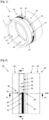
- a mechanical system (1) according to the invention comprises a guiding device (10) according to the invention, and an axis (2) mounted in the device (10).
- Axis (2) is represented by two dotted lines for the purpose of simplification.
- the device (10) is designed for guiding the axis (2) in frictional contact by sliding, in particular sliding with oscillation.
- a lubricant preferably grease
- the device (10) includes a metal friction component (20), a detection system (30) and a wireless communication system (40).
- the metal component (20) is formed by an annular ring (21), provided with an internal surface (22) and an external surface (23) of cylindrical profiles.
- the internal surface (22) constitutes a friction surface intended to receive the axis (2) in sliding friction contact.
- the surface (22) may include arrangements acting as a lubricant reserve.
- the arrangements may include cavities, grooves and/or other types of arrangements.
- the surfaces (22, 23) have annular grooves (24, 25) in the central part, connected by orifices (26) passing through the ring (21).
- the elements (24, 25, 26) constitute means of lubricating the surface (22).
- the ring (21) can be devoid of elements (24, 25, 26).
- the means for lubricating the surface (22) can be of any type adapted to the intended application.
- the surface (23) has an annular groove (27) formed on one side of the groove (25).
- the surfaces (22, 23) are connected by orifices (28) passing through the ring (21) at the edge of the groove (27).
- the elements (27, 28) constitute reception means of the detection system (30).
- the ring (21) is devoid of elements (24, 25, 26)
- the elements (27, 28) can be arranged in the central part.
- the groove (27) can be arranged in the central part, while the orifices (28) are arranged on an edge (29).
- each longitudinal edge (29) is defined over at most two-fifths of the length of the ring (21).
- each longitudinal edge (29) is defined over a third of the length of the ring (21).
- the thickness of the ring (21) depends on the intended application.
- the ring (21) may have a thickness of between 5 and 15 millimeters, or beyond. This thickness is defined over the functional range of the friction surface (22), excluding a possible shoulder formed on an edge (29).
- the detection system (30) is configured to detect wear of the friction surface (22).
- the detection system (30) could be configured to detect the clearance between the friction surface (22) and the surface of the axle (2).
- the sensing system (30) includes a conductive strip (31), a plurality of sensors (32) connected to the strip (31) via conductive wires (33), and a connector (34) configured to connect the system (30) to the system (40).
- the strip (31) consists of a sheet of conductive wires, integrating the wires (33).
- the connector (34) may include an electronic chip configured to transform current loss information into wear depth information. Alternatively, the connector (34) may comprise simple wires belonging to the strip (31).
- the conductive strip (31) is disposed in the annular groove (27) formed on the outer surface (23) of the metal component (20).
- the conductive strip (31) is connected, on the one hand, to each sensor (32) via the conductive wires (33) and, on the other hand, to the wireless communication system (40) via the connector (34).
- the detection system (30) comprises four sensors (32) distributed at 90° around the central axis (X20) of the component (20).
- the detection system (30) ensures wear detection over an angular range of 360° around the central axis (X20).
- the sensors (32) are arranged exclusively on a longitudinal edge (29) of the ring (21), without extending into the central part. Indeed, when the mechanical system (1) is in service, the mechanical stresses are generally concentrated on the edges (29) of the ring (21). Arranging the sensors (32) on an edge (29) rather than in the central part makes it possible to improve wear detection and the chances of implementing a predictive maintenance operation before a critical system malfunction (1).
- Each sensor (32) comprises several conductive wires (35, 36, 37), each having one end arranged at a given depth below the friction surface (22).
- the wear of the conductive wire (35, 36, 37) depends on the wear of the surface (22).
- the ends of the conductive wires (35, 36, 37) are arranged at different depths below the friction surface (22).
- the successive wear of the conductive wires (35, 36, 37) is linked to the progressive wear of the friction surface (22), according to different thresholds.
- the detection system (30) is configured to detect different wear thresholds of the friction surface (22).
- Each sensor (32) comprises a cylindrical casing (38) housed in an orifice (28) passing through the metal component (20) between the friction surface (22) and the external surface (23).
- This envelope (38) constitutes a means of indexing the angular and axial position of the sensor (32).
- Other solutions are possible to form angular and/or axial indexing means.
- the envelope (38) housed in an orifice (28) has the advantage of being a simple solution to implement.
- each sensor (32) comprises means for indexing its radial position relative to the friction surface (22).
- the radial indexing means may comprise a flange (39) formed on the cylindrical envelope (38) of the sensor (32).
- Other solutions are possible to form the radial indexing means, which make it possible to ensure that the wires (35, 36, 37) are positioned at the correct depth relative to the surface (22).
- the wireless communication system (40) is connected to the sensing system (30) and configured to transmit information relating to wear or play to the exterior of the guide device (10).
- the system (40) includes a transmitter (42) sending radio signals in all directions. If the device (40) is placed in a closed environment, the transmitter (42) can be configured to transmit the information through metal components having a total thickness greater than 10 millimeters. In practice, the signals can be transmitted in an axial direction to an external reader placed near the ring (21), through the parts of its environment.
- the transmitter (42) can consist of an RFID chip.
- Other technologies can be used without departing from the scope of the invention.
- the communications system (40) may include a power source for powering the detection system (30).
- FIG. 6 shows a variant of guiding device (10), comprising sensors (32) arranged on the two longitudinal edges (29), but not in the central part.
- the device (10) can advantageously be mounted in both directions, without the operator being forced to pay attention to its orientation. This configuration is also useful in the event of asymmetry in the distribution of mechanical stresses between the two edges (29).
- the communication system (40) has two transmitters (42), one on each side. This facilitates the connection between sensor (32) and transmitters (42), and ensures that a transmitter (42) is always close to the external reader placed near the device (10).
- the device (10) can be shaped differently from the figures 1 to 6 without departing from the scope of the invention, which is defined by the claims.
Landscapes
- Engineering & Computer Science (AREA)
- General Engineering & Computer Science (AREA)
- Mechanical Engineering (AREA)
- General Physics & Mathematics (AREA)
- Physics & Mathematics (AREA)
- Chemical & Material Sciences (AREA)
- Analytical Chemistry (AREA)
- Life Sciences & Earth Sciences (AREA)
- Health & Medical Sciences (AREA)
- Biochemistry (AREA)
- General Health & Medical Sciences (AREA)
- Immunology (AREA)
- Pathology (AREA)
- Arrangements For Transmission Of Measured Signals (AREA)
- Measurement Of Length, Angles, Or The Like Using Electric Or Magnetic Means (AREA)
- Oil, Petroleum & Natural Gas (AREA)
- Control Of Position, Course, Altitude, Or Attitude Of Moving Bodies (AREA)
Claims (10)
- Führungsvorrichtung (10), umfassend:- ein Metallbauteil (20) versehen mit einer Reibungsfläche (22), bestimmt zur Aufnahme eines Gegenstücks (2) in reibschlüssigem Kontakt;- ein System zur Erkennung (30) der Abnutzung der Reibungsfläche (22) oder eines Spiels zwischen der Reibungsfläche (22) und dem Gegenstück (2), das Detektionssystem (30) umfasst dabei einen oder mehrere Fühler (32); und- ein drahtloses Kommunikationssystem (40), verbunden mit dem Detektionssystem (30) und dazu konfiguriert, Informationen zur Abnutzung oder dem Spiel nach außerhalb der Führungsvorrichtung (10) zu übertragendadurch gekennzeichnet, dass der oder jeder Fühler (32) mehrere leitenden Drähte (35, 36, 37) umfasst, bei denen die Endstücke in verschiedenen Tiefen unter der Reibungsfläche (22), angeordnet sind, die Abnutzung des Leiters (35, 36, 37) entspricht der Abnutzung der Oberfläche (22) und dadurch dass der oder jeder Fühler (32) eine zylinderförmige Hülle (38) umfasst, untergebracht in einer Öffnung (28), die durch das Metallbauteil (20) zwischen der Reibungsfläche (22) und der Außenfläche (23) hindurchführt.
- Führungsvorrichtung (10) nach Anspruch 1, dadurch gekennzeichnet, dass sie ein Schmiermittel umfasst, das auf der Reibungsfläche (22) vorgesehen ist.
- Führungsvorrichtung (10) nach irgendeinem der vorstehenden Ansprüche, dadurch gekennzeichnet, dass die Reibungsfläche (22) Einrichtungen enthält, die als Schmiermittelreserve dienen.
- Führungsvorrichtung (10) nach irgendeinem der vorstehenden Ansprüche, dadurch gekennzeichnet, dass das Detektionssystem (30) konfiguriert ist zur Erkennung der Abnutzung der Reibungsfläche (22) in einem Winkelbereich von mindestens 3° um eine zentrale Achse (X20) des Metallbauteils (20) herum.
- Führungsvorrichtung (10) nach Anspruch 4, dadurch gekennzeichnet, dass das Detektionssystem (30) einen einzigen Fühler (32) umfasst, der die Erkennung der Abnutzung der Reibungsfläche (22) in einem Winkelbereich von mindestens 3° gewährleistet.
- Führungsvorrichtung (10) nach Anspruch 4, dadurch gekennzeichnet, dass das Detektionssystem (30) mehrere Fühler (32) enthält, die um die zentrale Achse (X20) des Metallbauteils (20) herum angeordnet sind und die Erkennung der Abnutzung in mindestens einem Winkelbereich von 60°, vorzugsweise in einem Winkelbereich von 360° gewährleisten.
- Führungsvorrichtung (10) nach irgendeinem der vorstehenden Ansprüche, dadurch gekennzeichnet, dass der oder die Fühler (32) ausschließlich über einen Längsrand (29) oder über zwei Längsränder (29) des Rings angeordnet sind, jeder Längsrand (29) ist definiert über höchstens zwei Fünftel der Länge des Rings (21).
- Führungsvorrichtung (10) nach irgendeinem der vorstehenden Ansprüche, dadurch gekennzeichnet, dass das Metallbauteil (20) aus einem Ring (21) mit einer radialen Dicke von mindestens 5 Millimetern besteht.
- Führungsvorrichtung (10) nach irgendeinem der vorstehenden Ansprüche, dadurch gekennzeichnet, dass das Metallbauteil (20) aus einem Ring (21) mit einer radialen Dicke von höchstens 5 Millimetern besteht.
- Mechanisches System (1), dadurch gekennzeichnet, dass es mindestens eine Führungsvorrichtung (10) enthält, nach einem der Ansprüche 1 bis 9 sowie ein Gegenstück (2), montiert in reibschlüssigem Kontakt mit der Reibungsfläche (22), vorzugsweise reibschlüssig mit Schwingung.
Applications Claiming Priority (2)
| Application Number | Priority Date | Filing Date | Title |
|---|---|---|---|
| FR2006879A FR3111985B1 (fr) | 2020-06-30 | 2020-06-30 | Dispositif de guidage et système mécanique comprenant un tel dispositif |
| PCT/FR2021/050968 WO2022003263A1 (fr) | 2020-06-30 | 2021-05-28 | Dispositif de guidage et systeme mecanique comprenant un tel dispositif |
Publications (2)
| Publication Number | Publication Date |
|---|---|
| EP4143531A1 EP4143531A1 (de) | 2023-03-08 |
| EP4143531B1 true EP4143531B1 (de) | 2024-01-03 |
Family
ID=72801645
Family Applications (1)
| Application Number | Title | Priority Date | Filing Date |
|---|---|---|---|
| EP21734889.5A Active EP4143531B1 (de) | 2020-06-30 | 2021-05-28 | Führungsgerät und mechanisches system einschliesslich eines solchen geräts |
Country Status (17)
| Country | Link |
|---|---|
| US (1) | US20230213068A1 (de) |
| EP (1) | EP4143531B1 (de) |
| JP (1) | JP2023530932A (de) |
| KR (1) | KR20230028262A (de) |
| CN (1) | CN115917290A (de) |
| AU (1) | AU2021298909A1 (de) |
| CA (1) | CA3179220A1 (de) |
| DK (1) | DK4143531T3 (de) |
| ES (1) | ES2971028T3 (de) |
| FI (1) | FI4143531T3 (de) |
| FR (1) | FR3111985B1 (de) |
| HU (1) | HUE065286T2 (de) |
| MX (1) | MX2022015617A (de) |
| PL (1) | PL4143531T3 (de) |
| PT (1) | PT4143531T (de) |
| WO (1) | WO2022003263A1 (de) |
| ZA (1) | ZA202212646B (de) |
Families Citing this family (1)
| Publication number | Priority date | Publication date | Assignee | Title |
|---|---|---|---|---|
| CN116335990B (zh) * | 2023-05-26 | 2023-08-11 | 无锡德申精密机械制造有限公司 | 一种汽车发动机水泵轴 |
Family Cites Families (17)
| Publication number | Priority date | Publication date | Assignee | Title |
|---|---|---|---|---|
| JPS56163410A (en) * | 1980-05-22 | 1981-12-16 | Mitsubishi Electric Corp | Abrasion detector of plain bearing |
| JPH0432565Y2 (de) * | 1986-08-29 | 1992-08-05 | ||
| JPH06193629A (ja) * | 1992-12-24 | 1994-07-15 | Ishikawajima Harima Heavy Ind Co Ltd | 軸受摩耗量検出装置 |
| JP2002181526A (ja) * | 2000-12-19 | 2002-06-26 | Mitsubishi Heavy Ind Ltd | 軸受隙間計測装置 |
| US6868711B2 (en) * | 2002-05-10 | 2005-03-22 | Sensoplan Aktiengesellschaft | Method for monitoring mechanical wear |
| JP2004084815A (ja) * | 2002-08-27 | 2004-03-18 | Komatsu Ltd | 軸受装置 |
| DE10324924B4 (de) * | 2003-06-03 | 2021-08-26 | Ab Skf | Verfahren zum Ermitteln einer von einem Gleitlager mit sphärisch oder zylindrisch ausgebildeten Lagerflächen aufgenommenen Last |
| CA2557445A1 (en) * | 2004-02-27 | 2005-09-09 | Mcgill University | Method and device for sensing wear |
| FR2882409B1 (fr) * | 2005-02-21 | 2008-09-05 | Ct Stephanois De Recherches | Organe de guidage autolubrifiant |
| DE202010004191U1 (de) * | 2010-03-23 | 2010-07-01 | Van Der Velden Barkemeyer Gmbh | Ruder für Schiffe |
| FR2999670B1 (fr) * | 2012-12-13 | 2014-11-28 | Hydromecanique & Frottement | Organe de guidage sous forme d'une bague metallique pour le montage avec frottement et avec capacite d''articulation et/ou de coulissement d'un axe. |
| DE102014110383A1 (de) * | 2014-04-01 | 2015-10-01 | Becker Marine Systems Gmbh & Co. Kg | Lager zum Lagern einer Welle, insbesondere eines Ruderschaftes, elektronische Lagerspielmessvorrichtung, Ruder umfassend ein Lager zum Lagern einer Welle und Verfahren zur Messung eines Verschleißes eines Lagers zum Lagern einer Welle |
| GB2534191A (en) * | 2015-01-16 | 2016-07-20 | Mahle Int Gmbh | Sliding bearing |
| DE202016102133U1 (de) * | 2016-04-21 | 2017-05-23 | Igus Gmbh | Gleitlager, Kunststoffgleitelement, System und Verwendung zur Verschleißerkennung |
| GB2565555B (en) * | 2017-08-15 | 2020-07-08 | Mahle Int Gmbh | Sliding component and method |
| AT521572B1 (de) * | 2018-08-29 | 2020-07-15 | Miba Gleitlager Austria Gmbh | Gleitlageranordnung |
| CN112840207A (zh) * | 2018-10-08 | 2021-05-25 | Sms集团有限公司 | 用于测量滑动支承或引导元件的磨损状态的设备和方法 |
-
2020
- 2020-06-30 FR FR2006879A patent/FR3111985B1/fr active Active
-
2021
- 2021-05-28 PT PT217348895T patent/PT4143531T/pt unknown
- 2021-05-28 DK DK21734889.5T patent/DK4143531T3/da active
- 2021-05-28 KR KR1020227042734A patent/KR20230028262A/ko active Pending
- 2021-05-28 JP JP2022576857A patent/JP2023530932A/ja active Pending
- 2021-05-28 ES ES21734889T patent/ES2971028T3/es active Active
- 2021-05-28 CN CN202180042348.5A patent/CN115917290A/zh active Pending
- 2021-05-28 PL PL21734889.5T patent/PL4143531T3/pl unknown
- 2021-05-28 FI FIEP21734889.5T patent/FI4143531T3/en active
- 2021-05-28 MX MX2022015617A patent/MX2022015617A/es unknown
- 2021-05-28 US US18/008,253 patent/US20230213068A1/en active Pending
- 2021-05-28 HU HUE21734889A patent/HUE065286T2/hu unknown
- 2021-05-28 WO PCT/FR2021/050968 patent/WO2022003263A1/fr not_active Ceased
- 2021-05-28 EP EP21734889.5A patent/EP4143531B1/de active Active
- 2021-05-28 AU AU2021298909A patent/AU2021298909A1/en active Pending
- 2021-05-28 CA CA3179220A patent/CA3179220A1/fr active Pending
-
2022
- 2022-11-21 ZA ZA2022/12646A patent/ZA202212646B/en unknown
Also Published As
| Publication number | Publication date |
|---|---|
| CA3179220A1 (fr) | 2022-01-06 |
| MX2022015617A (es) | 2023-02-01 |
| US20230213068A1 (en) | 2023-07-06 |
| ES2971028T3 (es) | 2024-06-03 |
| FR3111985A1 (fr) | 2021-12-31 |
| WO2022003263A1 (fr) | 2022-01-06 |
| FI4143531T3 (en) | 2024-02-14 |
| BR112022024326A2 (pt) | 2023-01-17 |
| PL4143531T3 (pl) | 2024-04-22 |
| ZA202212646B (en) | 2023-06-28 |
| DK4143531T3 (da) | 2024-01-15 |
| JP2023530932A (ja) | 2023-07-20 |
| PT4143531T (pt) | 2024-01-22 |
| KR20230028262A (ko) | 2023-02-28 |
| HUE065286T2 (hu) | 2024-05-28 |
| EP4143531A1 (de) | 2023-03-08 |
| AU2021298909A1 (en) | 2022-12-22 |
| CN115917290A (zh) | 2023-04-04 |
| FR3111985B1 (fr) | 2022-11-25 |
Similar Documents
| Publication | Publication Date | Title |
|---|---|---|
| EP0387459B1 (de) | Gleitlageranordnung mit auswechselbarem Messaufnehmer | |
| FR2994031A1 (fr) | Connecteur coaxial hyperfrequence pour relier deux cartes de circuit imprime | |
| EP4143449A1 (de) | Führungsvorrichtung und mechanisches system mit einer solchen vorrichtung | |
| EP4143531B1 (de) | Führungsgerät und mechanisches system einschliesslich eines solchen geräts | |
| EP1958871A1 (de) | Erfassung der Wiederherstellung des Drucks über eine Nebenleitung eines Stellglieds zur Flugsteuerung | |
| EP1330630B1 (de) | Mit sensor ausgestattetes wälzlager für lenkräder | |
| EP1039094B1 (de) | Rollenbohrmeissel mit Dichtungsvorrichtung | |
| EP3698069B1 (de) | Getriebe und machine mit einem solchen getriebe | |
| EP0943759B2 (de) | Anordnung für die Bewegungsübertragung zwischen einem Riegel und einem Kraftfahrzeugschloss | |
| WO2008046977A1 (fr) | Joint homocinetique | |
| EP1983309A1 (de) | Instrumentengesteuertes Gelenksystem | |
| FR2891330A1 (fr) | Module de securite pour transmission et assemblage correspondant | |
| FR2904671A1 (fr) | Systeme d'articulation instrumente. | |
| EP3443243B1 (de) | Hohlwellenschmiermittelkreislauf | |
| FR2692208A1 (fr) | Levier de changement de vitesses, notamment pour véhicule automobile. | |
| FR2895773A1 (fr) | Dispositif d'embrayage avec systeme integre de mesure de parametre moteur | |
| FR2966213A1 (fr) | Ensemble de liaison pour joint de transmission et joint de transmission associe | |
| FR3025268A1 (fr) | Accouplement avec goupille de securite | |
| FR2703117A1 (fr) | Joint de transmission du type à tulipe. |
Legal Events
| Date | Code | Title | Description |
|---|---|---|---|
| STAA | Information on the status of an ep patent application or granted ep patent |
Free format text: STATUS: UNKNOWN |
|
| STAA | Information on the status of an ep patent application or granted ep patent |
Free format text: STATUS: THE INTERNATIONAL PUBLICATION HAS BEEN MADE |
|
| PUAI | Public reference made under article 153(3) epc to a published international application that has entered the european phase |
Free format text: ORIGINAL CODE: 0009012 |
|
| STAA | Information on the status of an ep patent application or granted ep patent |
Free format text: STATUS: REQUEST FOR EXAMINATION WAS MADE |
|
| 17P | Request for examination filed |
Effective date: 20221128 |
|
| AK | Designated contracting states |
Kind code of ref document: A1 Designated state(s): AL AT BE BG CH CY CZ DE DK EE ES FI FR GB GR HR HU IE IS IT LI LT LU LV MC MK MT NL NO PL PT RO RS SE SI SK SM TR |
|
| P01 | Opt-out of the competence of the unified patent court (upc) registered |
Effective date: 20230527 |
|
| DAV | Request for validation of the european patent (deleted) | ||
| DAX | Request for extension of the european patent (deleted) | ||
| GRAP | Despatch of communication of intention to grant a patent |
Free format text: ORIGINAL CODE: EPIDOSNIGR1 |
|
| STAA | Information on the status of an ep patent application or granted ep patent |
Free format text: STATUS: GRANT OF PATENT IS INTENDED |
|
| INTG | Intention to grant announced |
Effective date: 20231005 |
|
| GRAS | Grant fee paid |
Free format text: ORIGINAL CODE: EPIDOSNIGR3 |
|
| GRAA | (expected) grant |
Free format text: ORIGINAL CODE: 0009210 |
|
| STAA | Information on the status of an ep patent application or granted ep patent |
Free format text: STATUS: THE PATENT HAS BEEN GRANTED |
|
| AK | Designated contracting states |
Kind code of ref document: B1 Designated state(s): AL AT BE BG CH CY CZ DE DK EE ES FI FR GB GR HR HU IE IS IT LI LT LU LV MC MK MT NL NO PL PT RO RS SE SI SK SM TR |
|
| REG | Reference to a national code |
Ref country code: GB Ref legal event code: FG4D Free format text: NOT ENGLISH |
|
| REG | Reference to a national code |
Ref country code: DK Ref legal event code: T3 Effective date: 20240111 Ref country code: CH Ref legal event code: EP |
|
| REG | Reference to a national code |
Ref country code: DE Ref legal event code: R096 Ref document number: 602021008375 Country of ref document: DE |
|
| REG | Reference to a national code |
Ref country code: PT Ref legal event code: SC4A Ref document number: 4143531 Country of ref document: PT Date of ref document: 20240122 Kind code of ref document: T Free format text: AVAILABILITY OF NATIONAL TRANSLATION Effective date: 20240116 |
|
| REG | Reference to a national code |
Ref country code: IE Ref legal event code: FG4D Free format text: LANGUAGE OF EP DOCUMENT: FRENCH Ref country code: NL Ref legal event code: FP |
|
| REG | Reference to a national code |
Ref country code: FI Ref legal event code: FGE |
|
| REG | Reference to a national code |
Ref country code: SE Ref legal event code: TRGR |
|
| REG | Reference to a national code |
Ref country code: LT Ref legal event code: MG9D |
|
| REG | Reference to a national code |
Ref country code: HU Ref legal event code: AG4A Ref document number: E065286 Country of ref document: HU |
|
| REG | Reference to a national code |
Ref country code: ES Ref legal event code: FG2A Ref document number: 2971028 Country of ref document: ES Kind code of ref document: T3 Effective date: 20240603 |
|
| PG25 | Lapsed in a contracting state [announced via postgrant information from national office to epo] |
Ref country code: IS Free format text: LAPSE BECAUSE OF FAILURE TO SUBMIT A TRANSLATION OF THE DESCRIPTION OR TO PAY THE FEE WITHIN THE PRESCRIBED TIME-LIMIT Effective date: 20240503 |
|
| PG25 | Lapsed in a contracting state [announced via postgrant information from national office to epo] |
Ref country code: LT Free format text: LAPSE BECAUSE OF FAILURE TO SUBMIT A TRANSLATION OF THE DESCRIPTION OR TO PAY THE FEE WITHIN THE PRESCRIBED TIME-LIMIT Effective date: 20240103 |
|
| PG25 | Lapsed in a contracting state [announced via postgrant information from national office to epo] |
Ref country code: GR Free format text: LAPSE BECAUSE OF FAILURE TO SUBMIT A TRANSLATION OF THE DESCRIPTION OR TO PAY THE FEE WITHIN THE PRESCRIBED TIME-LIMIT Effective date: 20240404 |
|
| PG25 | Lapsed in a contracting state [announced via postgrant information from national office to epo] |
Ref country code: RS Free format text: LAPSE BECAUSE OF FAILURE TO SUBMIT A TRANSLATION OF THE DESCRIPTION OR TO PAY THE FEE WITHIN THE PRESCRIBED TIME-LIMIT Effective date: 20240403 Ref country code: HR Free format text: LAPSE BECAUSE OF FAILURE TO SUBMIT A TRANSLATION OF THE DESCRIPTION OR TO PAY THE FEE WITHIN THE PRESCRIBED TIME-LIMIT Effective date: 20240103 |
|
| PG25 | Lapsed in a contracting state [announced via postgrant information from national office to epo] |
Ref country code: CZ Free format text: LAPSE BECAUSE OF FAILURE TO SUBMIT A TRANSLATION OF THE DESCRIPTION OR TO PAY THE FEE WITHIN THE PRESCRIBED TIME-LIMIT Effective date: 20240103 |
|
| PG25 | Lapsed in a contracting state [announced via postgrant information from national office to epo] |
Ref country code: RS Free format text: LAPSE BECAUSE OF FAILURE TO SUBMIT A TRANSLATION OF THE DESCRIPTION OR TO PAY THE FEE WITHIN THE PRESCRIBED TIME-LIMIT Effective date: 20240403 Ref country code: LT Free format text: LAPSE BECAUSE OF FAILURE TO SUBMIT A TRANSLATION OF THE DESCRIPTION OR TO PAY THE FEE WITHIN THE PRESCRIBED TIME-LIMIT Effective date: 20240103 Ref country code: IS Free format text: LAPSE BECAUSE OF FAILURE TO SUBMIT A TRANSLATION OF THE DESCRIPTION OR TO PAY THE FEE WITHIN THE PRESCRIBED TIME-LIMIT Effective date: 20240503 Ref country code: HR Free format text: LAPSE BECAUSE OF FAILURE TO SUBMIT A TRANSLATION OF THE DESCRIPTION OR TO PAY THE FEE WITHIN THE PRESCRIBED TIME-LIMIT Effective date: 20240103 Ref country code: GR Free format text: LAPSE BECAUSE OF FAILURE TO SUBMIT A TRANSLATION OF THE DESCRIPTION OR TO PAY THE FEE WITHIN THE PRESCRIBED TIME-LIMIT Effective date: 20240404 Ref country code: CZ Free format text: LAPSE BECAUSE OF FAILURE TO SUBMIT A TRANSLATION OF THE DESCRIPTION OR TO PAY THE FEE WITHIN THE PRESCRIBED TIME-LIMIT Effective date: 20240103 |
|
| PG25 | Lapsed in a contracting state [announced via postgrant information from national office to epo] |
Ref country code: LV Free format text: LAPSE BECAUSE OF FAILURE TO SUBMIT A TRANSLATION OF THE DESCRIPTION OR TO PAY THE FEE WITHIN THE PRESCRIBED TIME-LIMIT Effective date: 20240103 |
|
| REG | Reference to a national code |
Ref country code: DE Ref legal event code: R097 Ref document number: 602021008375 Country of ref document: DE |
|
| PG25 | Lapsed in a contracting state [announced via postgrant information from national office to epo] |
Ref country code: SM Free format text: LAPSE BECAUSE OF FAILURE TO SUBMIT A TRANSLATION OF THE DESCRIPTION OR TO PAY THE FEE WITHIN THE PRESCRIBED TIME-LIMIT Effective date: 20240103 |
|
| PG25 | Lapsed in a contracting state [announced via postgrant information from national office to epo] |
Ref country code: EE Free format text: LAPSE BECAUSE OF FAILURE TO SUBMIT A TRANSLATION OF THE DESCRIPTION OR TO PAY THE FEE WITHIN THE PRESCRIBED TIME-LIMIT Effective date: 20240103 |
|
| PG25 | Lapsed in a contracting state [announced via postgrant information from national office to epo] |
Ref country code: SK Free format text: LAPSE BECAUSE OF FAILURE TO SUBMIT A TRANSLATION OF THE DESCRIPTION OR TO PAY THE FEE WITHIN THE PRESCRIBED TIME-LIMIT Effective date: 20240103 |
|
| PG25 | Lapsed in a contracting state [announced via postgrant information from national office to epo] |
Ref country code: SM Free format text: LAPSE BECAUSE OF FAILURE TO SUBMIT A TRANSLATION OF THE DESCRIPTION OR TO PAY THE FEE WITHIN THE PRESCRIBED TIME-LIMIT Effective date: 20240103 Ref country code: SK Free format text: LAPSE BECAUSE OF FAILURE TO SUBMIT A TRANSLATION OF THE DESCRIPTION OR TO PAY THE FEE WITHIN THE PRESCRIBED TIME-LIMIT Effective date: 20240103 Ref country code: EE Free format text: LAPSE BECAUSE OF FAILURE TO SUBMIT A TRANSLATION OF THE DESCRIPTION OR TO PAY THE FEE WITHIN THE PRESCRIBED TIME-LIMIT Effective date: 20240103 |
|
| PLBE | No opposition filed within time limit |
Free format text: ORIGINAL CODE: 0009261 |
|
| STAA | Information on the status of an ep patent application or granted ep patent |
Free format text: STATUS: NO OPPOSITION FILED WITHIN TIME LIMIT |
|
| 26N | No opposition filed |
Effective date: 20241007 |
|
| REG | Reference to a national code |
Ref country code: CH Ref legal event code: PL |
|
| PG25 | Lapsed in a contracting state [announced via postgrant information from national office to epo] |
Ref country code: MC Free format text: LAPSE BECAUSE OF FAILURE TO SUBMIT A TRANSLATION OF THE DESCRIPTION OR TO PAY THE FEE WITHIN THE PRESCRIBED TIME-LIMIT Effective date: 20240103 |
|
| REG | Reference to a national code |
Ref country code: AT Ref legal event code: UEP Ref document number: 1647267 Country of ref document: AT Kind code of ref document: T Effective date: 20240103 |
|
| PG25 | Lapsed in a contracting state [announced via postgrant information from national office to epo] |
Ref country code: LU Free format text: LAPSE BECAUSE OF NON-PAYMENT OF DUE FEES Effective date: 20240528 |
|
| PG25 | Lapsed in a contracting state [announced via postgrant information from national office to epo] |
Ref country code: MC Free format text: LAPSE BECAUSE OF FAILURE TO SUBMIT A TRANSLATION OF THE DESCRIPTION OR TO PAY THE FEE WITHIN THE PRESCRIBED TIME-LIMIT Effective date: 20240103 Ref country code: LU Free format text: LAPSE BECAUSE OF NON-PAYMENT OF DUE FEES Effective date: 20240528 Ref country code: CH Free format text: LAPSE BECAUSE OF NON-PAYMENT OF DUE FEES Effective date: 20240531 |
|
| PG25 | Lapsed in a contracting state [announced via postgrant information from national office to epo] |
Ref country code: IE Free format text: LAPSE BECAUSE OF NON-PAYMENT OF DUE FEES Effective date: 20240528 |
|
| PG25 | Lapsed in a contracting state [announced via postgrant information from national office to epo] |
Ref country code: SI Free format text: LAPSE BECAUSE OF FAILURE TO SUBMIT A TRANSLATION OF THE DESCRIPTION OR TO PAY THE FEE WITHIN THE PRESCRIBED TIME-LIMIT Effective date: 20240103 |
|
| PGFP | Annual fee paid to national office [announced via postgrant information from national office to epo] |
Ref country code: NL Payment date: 20250429 Year of fee payment: 5 |
|
| PGFP | Annual fee paid to national office [announced via postgrant information from national office to epo] |
Ref country code: FI Payment date: 20250423 Year of fee payment: 5 |
|
| PGFP | Annual fee paid to national office [announced via postgrant information from national office to epo] |
Ref country code: PL Payment date: 20250425 Year of fee payment: 5 Ref country code: DE Payment date: 20250513 Year of fee payment: 5 |
|
| PGFP | Annual fee paid to national office [announced via postgrant information from national office to epo] |
Ref country code: ES Payment date: 20250610 Year of fee payment: 5 Ref country code: GB Payment date: 20250521 Year of fee payment: 5 Ref country code: DK Payment date: 20250428 Year of fee payment: 5 |
|
| PGFP | Annual fee paid to national office [announced via postgrant information from national office to epo] |
Ref country code: HU Payment date: 20250430 Year of fee payment: 5 Ref country code: NO Payment date: 20250425 Year of fee payment: 5 |
|
| PGFP | Annual fee paid to national office [announced via postgrant information from national office to epo] |
Ref country code: BE Payment date: 20250527 Year of fee payment: 5 Ref country code: IT Payment date: 20250508 Year of fee payment: 5 |
|
| PGFP | Annual fee paid to national office [announced via postgrant information from national office to epo] |
Ref country code: PT Payment date: 20250423 Year of fee payment: 5 |
|
| PGFP | Annual fee paid to national office [announced via postgrant information from national office to epo] |
Ref country code: FR Payment date: 20250522 Year of fee payment: 5 |
|
| PGFP | Annual fee paid to national office [announced via postgrant information from national office to epo] |
Ref country code: BG Payment date: 20250425 Year of fee payment: 5 |
|
| PGFP | Annual fee paid to national office [announced via postgrant information from national office to epo] |
Ref country code: RO Payment date: 20250506 Year of fee payment: 5 Ref country code: AT Payment date: 20250721 Year of fee payment: 5 |
|
| PGFP | Annual fee paid to national office [announced via postgrant information from national office to epo] |
Ref country code: TR Payment date: 20250516 Year of fee payment: 5 |
|
| PGFP | Annual fee paid to national office [announced via postgrant information from national office to epo] |
Ref country code: SE Payment date: 20250519 Year of fee payment: 5 |
|
| PG25 | Lapsed in a contracting state [announced via postgrant information from national office to epo] |
Ref country code: CY Free format text: LAPSE BECAUSE OF FAILURE TO SUBMIT A TRANSLATION OF THE DESCRIPTION OR TO PAY THE FEE WITHIN THE PRESCRIBED TIME-LIMIT; INVALID AB INITIO Effective date: 20210528 |