EP1530023A2 - Vorrichtung und Verfahren zur Detektion der magnetischen Nordrichtung - Google Patents
Vorrichtung und Verfahren zur Detektion der magnetischen Nordrichtung Download PDFInfo
- Publication number
- EP1530023A2 EP1530023A2 EP04026570A EP04026570A EP1530023A2 EP 1530023 A2 EP1530023 A2 EP 1530023A2 EP 04026570 A EP04026570 A EP 04026570A EP 04026570 A EP04026570 A EP 04026570A EP 1530023 A2 EP1530023 A2 EP 1530023A2
- Authority
- EP
- European Patent Office
- Prior art keywords
- geomagnetism
- angle
- magnetic field
- dimensional
- field intensity
- Prior art date
- Legal status (The legal status is an assumption and is not a legal conclusion. Google has not performed a legal analysis and makes no representation as to the accuracy of the status listed.)
- Withdrawn
Links
- 238000000034 method Methods 0.000 title claims description 20
- 238000004364 calculation method Methods 0.000 claims description 23
- 238000006243 chemical reaction Methods 0.000 claims description 21
- 230000005358 geomagnetic field Effects 0.000 abstract 4
- 230000001413 cellular effect Effects 0.000 description 44
- 238000005516 engineering process Methods 0.000 description 9
- 238000010276 construction Methods 0.000 description 5
- 230000007423 decrease Effects 0.000 description 2
- 230000007547 defect Effects 0.000 description 2
- 230000005389 magnetism Effects 0.000 description 2
- 238000001514 detection method Methods 0.000 description 1
- 230000000694 effects Effects 0.000 description 1
- 230000002452 interceptive effect Effects 0.000 description 1
- 239000004973 liquid crystal related substance Substances 0.000 description 1
- 239000000696 magnetic material Substances 0.000 description 1
- 239000000463 material Substances 0.000 description 1
- 230000004048 modification Effects 0.000 description 1
- 238000012986 modification Methods 0.000 description 1
- 239000004065 semiconductor Substances 0.000 description 1
- 239000007787 solid Substances 0.000 description 1
Images



Classifications
-
- G—PHYSICS
- G01—MEASURING; TESTING
- G01C—MEASURING DISTANCES, LEVELS OR BEARINGS; SURVEYING; NAVIGATION; GYROSCOPIC INSTRUMENTS; PHOTOGRAMMETRY OR VIDEOGRAMMETRY
- G01C21/00—Navigation; Navigational instruments not provided for in groups G01C1/00 - G01C19/00
- G01C21/20—Instruments for performing navigational calculations
-
- G—PHYSICS
- G01—MEASURING; TESTING
- G01C—MEASURING DISTANCES, LEVELS OR BEARINGS; SURVEYING; NAVIGATION; GYROSCOPIC INSTRUMENTS; PHOTOGRAMMETRY OR VIDEOGRAMMETRY
- G01C17/00—Compasses; Devices for ascertaining true or magnetic north for navigation or surveying purposes
- G01C17/02—Magnetic compasses
- G01C17/28—Electromagnetic compasses
Definitions
- This invention relates to the art of a magnetic north detection for detecting the magnetic north direction, particularly, relates to a magnetic north detecting device and a magnetic north detecting method for detecting a magnetic north direction, based on geomagnetism magnetic filed intensity measured by a 3-dimensional geomagnetism sensor.
- This invention is applied to mainly to cellular phones.
- the navigation function uses position information obtained by a predetermined position detecting means and magnetic north direction calculated by a magnetic north direction sensor for detecting the magnetic north direction based on measuring data of the geomagnetism.
- the magnetic north direction sensor comprises a 2-dimensional geomagnetism sensor unit 1 for detecting geomagnetism magnetic field intensities of two directions perpendicular to each other and a 2-dimensional operation functional section 2 which calculates the magnetic north direction from the geomagnetism magnetic field intensities measured by two geomagnetism sensors included in the 2-dimensional geomagnetism sensor unit 1.
- the particular magnetic north direction sensor is disclosed in, for example, Application Note AN00022 "Electronic Compass Design using KMZ51 and KMZ52" published by Philips Semiconductors.
- the calculation method of the 2-dimensional operation functional section 2 utilizes the following principle. Specifically, when an angle formed by the magnetic north direction and an axis of the sensor is denoted by, for example, ⁇ , one of two geomagnetism sensors placed on the 2-dimensional plane shows magnetic field intensity proportional to sin( ⁇ ), while the other shows magnetic field intensity proportional to cos( ⁇ ). In order to calculate the magnetic north direction angle ⁇ backward from the magnetic field intensities measured by two geomagnetism sensors, the ratio of the magnetic field intensities is fined, and tan-1 of the ratio is calculated.
- the 2-dimensional geomagnetism sensor unit is level to the earth surface.
- the sensor unit 1 When the sensor unit 1 is not placed on a level to the earth surface, it produces an error in reading of the magnetic north direction.
- the reason of producing the error is that the geomagnetism direction is not level to the earth surface and, therefore, is inclined to the earth surface by so-called "dip angle".
- the dip angle in Japan and environs is distributed in a range of about 44 to 59 degrees.
- horizontal and perpendicular components of the geomagnetism magnetic field are equal to each other. Therefore, the perpendicular component is substantially equal to or larger than the horizontal component in Japan and environs.
- the error of the magnetic north direction due to the 2-dimensional geomagnetism sensor unit not being kept level to the earth surface is one of the interfering factors in gaining the market share of cellar phones having a magnetic north detecting function.
- An object of the present invention is to provide a magnetic north detecting device and magnetic north detecting method which can detect a right direction of the magnetic north even when the geomagnetism sensor unit is inclined to the earth surface.
- a magnetic north detecting device comprising:
- a magnetic north detecting method performed by using a 3-dimensional geomagnetism sensor unit including three geomagnetism sensors for detecting respective components of a geomagnetism magnetic field intensity in respective directions of three coordinate axes perpendicular to each other, the method comprising the steps of:
- the 3-dimensional operation functional section can include a function for finding the ⁇ such that a D value shown in a following equation (e) is substantially equal to zero, by repeating steps of a first step of assuming the ⁇ , a second step of calculating the ⁇ by using a following equation (d), and a third step of calculating the D value by using the equation (e), in this order.
- the 3-dimensional operation functional section can include a function for calculating an absolute value of the geomagnetism magnetic field intensity from the respective components of the geomagnetism magnetic field intensity in the respective directions of the three coordinate axes and carrying out a presumption calculation of the dip angle of the geomagnetism based on the calculated absolute value of the geomagnetism and a correlation data between absolute value of the geomagnetism and dip angle value.
- an object of the present invention is to overcome the defect of producing a big error in indication of the magnetic north direction due to the 2-dimensional geomagnetism sensor unit not being kept level to the earth surface in the case of using a conventional 2-dimensional geomagnetism sensor unit.
- One method for preventing the above defect is to add another geomagnetism sensor in addition to the two geomagnetism sensors placed on the 2-dimensional plane, that is, to use a 3-dimensional geomagnetism sensor unit.
- the additional sensor is placed on an axis perpendicular to the 2-dimensional plane.
- the 3-dimensional geomagnetism sensor unit it is possible to obtain information on the magnetic field intensity in respective directions of the three axes in sensor coordinate system which is formed by the three geomagnetism sensors included in the sensor unit, but the information on the magnetic field intensity thus obtained has no meaning for finding the magnetic north direction because it is impossible to specify a tilt angle of the 3-dimensional geomagnetism sensor unit from the earth surface.
- the magnetic north detecting device comprises: a 3-dimensional geomagnetism sensor unit including three geomagnetism sensors for detecting respective components of a geomagnetism magnetic field intensity in respective directions of three coordinate axes perpendicular to each other; and a 3-dimensional operation functional section for carrying out an operation on the basis of the components of the geomagnetism magnetic field intensity detected by the geomagnetism sensors included in the 3-dimensional geomagnetism sensor unit, and calculating a magnetic north direction of the geomagnetism.
- a 3-dimensional geomagnetism sensor unit including three geomagnetism sensors for detecting respective components of a geomagnetism magnetic field intensity in respective directions of three coordinate axes perpendicular to each other
- a 3-dimensional operation functional section for carrying out an operation on the basis of the components of the geomagnetism magnetic field intensity detected by the geomagnetism sensors included in the 3-dimensional geomagnetism sensor unit, and calculating a magnetic north direction of the geomagnetism.
- FIG. 1 is a drawing showing the construction of a conventional magnetic north detecting device.
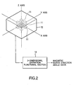
- FIG. 2 is a drawing schematically showing the construction of a magnetic north detecting device according to one embodiment of the present invention.
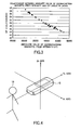
- FIG. 3 is a graph showing the relationship between the absolute value of the geomagnetism magnetic field intensity and the dip angle in Japan.
- FIG. 4 is a drawing for explaining the case where a cellular phone is placed on a level to the earth surface.
- FIG. 5 is a drawing for explaining the case where a cellular phone is inclined at a pitch rotation angle.
- FIG. 6 is a drawing for explaining the case where a cellular phone is inclined at a roll rotation angle.
- FIG. 7 is a drawing for explaining the sensor coordinate system formed by the 3-dimensional geomagnetism sensor unit and the earth surface coordinate system according to the present invention.
- FIG. 8 is a flow chart explaining the actual algorithm in the 3-dimensional operation functional section used for the magnetic north detecting device according to the present invention.
- FIG. 9 is a flow chart explaining the calculation procedure of the numerical example to actually find a magnetic north direction according to the present invention.
- FIG. 2 is a drawing schematically showing the construction of a magnetic north detecting device according to one embodiment of the present invention.
- the magnetic north detecting device comprises: a 3-dimensional geomagnetism sensor unit 12 having three geomagnetism sensors 11 for detecting respective components of a geomagnetism magnetic field intensity in respective directions of three coordinate axes perpendicular to each other; and a 3-dimensional operation functional section 13 for carrying out an calculation on the basis of the components of the geomagnetism magnetic field intensity detected by the geomagnetism sensors 11, and calculating a magnetic north direction of the geomagnetism.
- the respective magnetic sensors 11 detect not only the absolute value of the components of the geomagnetism magnetic field intensity in the respective directions of the three coordinate axes but also their signs of plus or minus.
- a geomagnetism sensor based on fluxgate technologies, MI technologies, Hall technologies, GIGS technologies or others is applicable for the geomagnetism sensor of the present invention.
- the geomagnetism sensor based on the GIGS technologies in which soft magnetic materials are arranged on both sides of a nano-granular GMR (Giant Magneto Resistant) material is specially fitted for the geomagnetism sensor constituting the 3-dimensional geomagnetism sensor unit 12, because it can be miniaturized.
- the 3-dimensional operation functional section 13 detects the magnetic north based on the following technology concept.
- the degrees of freedom specifying a direction of a vector in 3-dimensional space are two. Therefore, it is possible to specify the direction of one vector if two independent conditions, for example, two angles, are defined.
- the magnetic north direction is specified under the following two conditions.
- values of the dip angle in Japan vary from 44 to 59 degrees through the whole of Japan, and are all included in 49 degrees (at Tokyo and environs) minus five to plus 10 degrees.
- Table 1 shows representative examples of the relationship between the absolute value of the geomagnetism magnetic field intensity and the dip angle of the geomagnetism in various parts of Japan.
- FIG. 3 is a graph showing the relationship between of the absolute value of the geomagnetism magnetic field intensity and the dip angle in various parts of Japan.
- the dip angle has a close relationship with the latitude in light of the principle of generation of the dip angle. The reason that the range of the plus side of the dip angle is larger than that of the minus side in Japan is that the Japanese Islands have curved at near Tokyo, and the latitude range of the east area from Tokyo (the east Japan) is larger than that of the west area (the west Japan).
- the tilt angle of the geomagnetism magnetic field sensor unit is replaced by the angle of a cellular phone on the assumption that the 3-dimensional geomagnetism sensor unit included in the magnetic north detecting device according to the present invention is installed in the cellular phone.
- FIGS. 4, 5, and 6 show a direction of the cellular phone 15 equipped with the magnetic north detecting device including the 3-dimensional geomagnetism sensor unit, and the physical relationship between the cellular phone 15 and a person 16 who uses the cellular phone 15.
- Three coordinate axes in these drawings are axes of a sensor coordinate system of the geomagnetism sensor unit.
- An Xs axis extends from left to right, and a Ys axis extends from near side to far side as viewed from the person 16.
- a Zs axis is perpendicular to both the Xs and Ys axes.
- FIG. 4 shows the state where the cellular phone 15 is placed on a level to the earth surface.
- both the Xs and Ys axes are horizontal to the earth surface, and the Zs axis is vertical to the earth surface.
- the correct magnetic north direction can be detected by using two magnetic field components along the Xs and the Ys axes.
- the cellular phone 15 when the cellular phone 15 is actually used, the cellular phone 15 is not kept level in many cases. For example, in the case where the person put the cellular phone to his ear for a talk, it is considered that the angle of the cellular phone 15 is random, and thus it is difficult to specify the angle of the cellular phone 15. On the other hand, in the case where the person uses the cellular phone 15 for navigation, it is considered that the angle of the cellular phone 15 is not random at all and there is a certain restriction of the angle of the cellular phone. This will be explained below.
- the cellular phone 15 is a ship, and terms relating to a deflection of an angle generally used by a ship is used.
- a vertical direction deflection is called "pitch”
- a lateral direction deflection is called “roll”
- a deflection of the course is called “yaw”.
- Any case where the cellular phone 15 is inclined is classified into two cases.
- the first case which corresponds to a pitch rotation, is that the cellular phone rotates around the Xs axis as shown in Fig. 5.
- the second case which corresponds to a roll rotation, is that the cellular phone rotates around the Ys axis as shown in Fig. 6. Since the yaw which is the third deflection is just deflection of a direction to be calculated, the yaw is excluded from an error factor.
- the person 16 who uses the cellular phone 15 lies, but even in this case, it is considered that the person 16 uses the cellular phone 15 on navigation such that the Xs axis is also almost horizontally to the earth surface. This is because, in the case where the Xs axis is inclined to the earth surface, the meaning of a direction on a map shown up in the screen is obscure for the person 16.
- the magnetic north direction is specified on the basis of the two conditions, namely, the dip angle of the geomagnetism and the restriction of the angle of the 3-dimensional geomagnetism sensor unit to the earth surface in the case where the cellular phone 15 is used. Since the degrees of freedom generally specifying the direction of the vector in 3-dimensional space are two, as above-mentioned, it is possible to detect the magnetic north under the above two conditions.
- 3-dimensional coordinate system based on the 3-dimensional geomagnetism sensor unit installed in the cellular phone 15 is defined as a sensor coordinate system, and three axes of the sensor coordinate system are expressed by Xs, Ys, and Zs as shown in FIG. 7.
- the 3-dimensional geomagnetism sensor unit is installed within the cellular phone such that the Xs axis corresponds with the width direction of the cellular phone.
- the Xs axis extends from left to right as viewed from the person 16 who uses the cellular phone 15. As mentioned above, it is assumed that there is no roll rotation in this invention.
- the direction of the Xs axis is on a level line (horizontal) to the earth surface.
- a coordinate system based on the earth is defined as the earth coordinate system having three axes of Xe, Ye, Ze.
- the Xe and Ye axes are on a level to the earth surface, and the direction of the Ye axis is in agreement with the magnetic north direction.
- the Ze axis is perpendicular to the earth surface.
- suitable coordinate rotation can be applied to the Xs-Ys-Zs sensor coordinate system so that a converted coordinate system converted by the rotation coincides with the Xe-Ye-Ze earth coordinate system, the identification of the magnetic north direction in the sensor coordinate system is possible.
- permissible rotations are limited to a rotation around the Xs axis corresponding to the pitch rotation and a rotation around Zs' axis, where three axes of a converted coordinate system after the rotation around the Xs axis are expressed by Xs', Ys', and Zs'.
- a rotation around the Ys axis is not considered. This corresponds to the basic concept of the present invention in that there is no roll rotation.
- the vector direction of the magnetic field of the geomagnetism is in a plane formed by the Ye and Ze axes and has a predetermined dip angle referring to plane formed by the Xe and Ye axes, i.e. the earth surface.
- the problem to be solved is to suitably select a first angle and a second angle described below. Specifically, if following two coordinate rotations (1) and (2) are successively carried out,
- the Xs axis is horizontal to the earth surface, the Xs axis is in the plane formed by the Xe and Ye axes of the earth coordinate system. Accordingly, it is possible to specify the magnetic north direction by calculating a magnetic north direction angle ⁇ which is defined as an angle measured in counterclockwise between the Xs axis and the Ye axis.
- the plane formed by the Xe and Ye axes is level to the earth surface, and the magnetic north direction coincides with the Ye axis.
- the Xs axis of the sensor coordinate system is in the plane formed by the Xe and Ye axes in the earth coordinate system. Therefore, it is possible to specify the magnetic north direction by finding an angle of the Ye axis from the Xs axis.
- it is possible to specify the magnetic north direction by calculating the magnetic north direction angle ⁇ which is defined as the angle measured in counterclockwise between the Xs and Ye axes.
- This vector i.e. the Xs axis-pointing-vector referring to the earth coordinate system after the rotations, is in the plane formed by the Xe and Ye axes and rotates in clockwise at an angle ⁇ from the Xe axis.
- the clockwise means a minus angle rotation.
- care must be taken to the sign of the angle.
- the sensor coordinate system becomes identical to the earth coordinate system by selecting the angles ⁇ and ⁇ , then, it means that the sensor coordinate system was originally rotated at the angles - ⁇ and - ⁇ referring to the earth coordinate system.
- the tan -1 routine generally takes an angle between - ⁇ /2 to ⁇ /2 (principal value)
- a correct value of ⁇ cannot be obtained by only taking tan -1 .
- ⁇ is selected, followed by substituting the ⁇ + ⁇ for ⁇ , and the D is calculated again by the same procedure as STEP 1 to STEP 3, then acquired D value is expressed by D'.
- the step value of ⁇ should be suitably determined on the balance of required calculation accuracy and computation time.
- ⁇ x D 1 ⁇ ⁇ 2 - D 2 ⁇ ⁇ 1 D 1 - D 2
- FIG. 3 is a graph showing the same relationship. As shown in FIG. 3, there is a clear correlation in which the dip angle value decreases as the absolute value of the geomagnetism magnetic field intensity increases. Referring to this correlation, if we know the absolute value of the geomagnetism magnetic field intensity, it is possible to presume the dip angle more accurately.
- the absolute value of the geomagnetism magnetic field intensity is a quantity unrelated to the tilt angle of the 3-dimensional geomagnetism sensor unit, the absolute value of the geomagnetism magnetic field intensity can always be calculated when the 3-dimensional magnetic field intensity is measured.
- calculating the dip angle from the absolute value of the geomagnetism magnetic field intensity can be performed by expressing the graph shown in FIG. 3 in the form of a power series.
- FIG. 3 shows an example of Japan
- Similar correlation holds in everywhere on the earth.
- An overall tendency has a dense relation with the latitude.
- the absolute value of the geomagnetism magnetic field intensity gradually decreases, while the dip angle gradually increases, as the latitude increases from the equator to the two poles. If this correlation is expressed by the approximated curve, it is also possible to presume the dip angle from the absolute value of the geomagnetism magnetic field intensity in a global scale.
- the value of the angle ⁇ corresponding to the pitch rotation angle ⁇ of 30 degrees is -40 degrees. Therefore, according to the above equation (24), the magnetic north direction angle becomes 130 degrees, which agrees with the magnetic north direction angle initially assumed. In other word, we successfully guessed the initially assumed magnetic north direction angle by employing the present invention.
- the magnetic north detecting device of the present invention was applied to the navigation system of a cellular phone, however, can also be applied to other navigation system. Further, in the above-mentioned embodiment, an example of the algorithm of operation was show, but is not limited to it in the embodiment described above.
Landscapes
- Engineering & Computer Science (AREA)
- Radar, Positioning & Navigation (AREA)
- Remote Sensing (AREA)
- Physics & Mathematics (AREA)
- General Physics & Mathematics (AREA)
- Electromagnetism (AREA)
- Automation & Control Theory (AREA)
- Measuring Magnetic Variables (AREA)
- Navigation (AREA)
- Geophysics And Detection Of Objects (AREA)
Applications Claiming Priority (2)
| Application Number | Priority Date | Filing Date | Title |
|---|---|---|---|
| JP2003417262 | 2003-11-10 | ||
| JP2003417262 | 2003-11-10 |
Publications (2)
| Publication Number | Publication Date |
|---|---|
| EP1530023A2 true EP1530023A2 (de) | 2005-05-11 |
| EP1530023A3 EP1530023A3 (de) | 2007-06-20 |
Family
ID=34431645
Family Applications (1)
| Application Number | Title | Priority Date | Filing Date |
|---|---|---|---|
| EP04026570A Withdrawn EP1530023A3 (de) | 2003-11-10 | 2004-11-09 | Vorrichtung und Verfahren zur Detektion der magnetischen Nordrichtung |
Country Status (3)
| Country | Link |
|---|---|
| US (1) | US6962001B2 (de) |
| EP (1) | EP1530023A3 (de) |
| CN (1) | CN100516774C (de) |
Cited By (1)
| Publication number | Priority date | Publication date | Assignee | Title |
|---|---|---|---|---|
| CN103115624A (zh) * | 2013-01-24 | 2013-05-22 | 南京航空航天大学 | 一种基于地磁匹配的地磁日变修正方法 |
Families Citing this family (7)
| Publication number | Priority date | Publication date | Assignee | Title |
|---|---|---|---|---|
| KR100847382B1 (ko) * | 2004-08-10 | 2008-07-18 | 야마하 가부시키가이샤 | 방위 데이터 생성 방법, 방위 센서 유닛 및 휴대 전자 기기 |
| US7159326B2 (en) * | 2005-01-14 | 2007-01-09 | Nokia Corporation | Electronic device, computer program product and method of operating built-in compass |
| JP4919142B2 (ja) * | 2005-10-19 | 2012-04-18 | アイチ・マイクロ・インテリジェント株式会社 | 磁気コンパス |
| US7832111B2 (en) * | 2008-09-09 | 2010-11-16 | Memsic, Inc. | Magnetic sensing device for navigation and detecting inclination |
| US8321161B1 (en) * | 2010-09-17 | 2012-11-27 | The United States of America as represented by the Secretarty of the Navy | Autonomous magnetic measurement system |
| US8843338B2 (en) | 2011-07-29 | 2014-09-23 | Nokia Corporation | Processing Data for Calibration |
| CN112653249B (zh) * | 2019-10-10 | 2023-06-06 | 北京小米移动软件有限公司 | 无线充电系统,充电区域的确定方法及装置、电子设备 |
Citations (1)
| Publication number | Priority date | Publication date | Assignee | Title |
|---|---|---|---|---|
| JP2003166825A (ja) * | 2001-12-04 | 2003-06-13 | Nec Tokin Corp | 磁気センサ装置用地球磁極方位計算方法 |
Family Cites Families (14)
| Publication number | Priority date | Publication date | Assignee | Title |
|---|---|---|---|---|
| US4797841A (en) * | 1983-11-28 | 1989-01-10 | Magnavox Government And Industrial Electronics Company | Method and apparatus for automatic calibration of magnetic compass |
| US5525901A (en) * | 1993-02-02 | 1996-06-11 | Beaudreau Electric, Inc. | Sensor systems for monitoring and measuring angular position in two or three axes |
| JP3096413B2 (ja) * | 1995-11-02 | 2000-10-10 | キヤノン電子株式会社 | 磁気検出素子、磁気センサー、地磁気検出型方位センサー、及び姿勢制御用センサー |
| US6105265A (en) * | 1995-06-07 | 2000-08-22 | Gloor; Hans | Tilt-compensating indicator device for a compass |
| US6049989A (en) * | 1998-07-08 | 2000-04-18 | Lee; Chiu-Shan | Three-dimensional homologous surveying method and the related instrument |
| JP3782915B2 (ja) * | 2000-02-16 | 2006-06-07 | セイコーインスツル株式会社 | 磁気センサを有する電子機器 |
| FR2806158B1 (fr) * | 2000-03-07 | 2002-05-17 | Commissariat Energie Atomique | Procede pour determiner la position ou l'orientation d'un objet a l'aide d'un champ magnetique et dispositif correspondant |
| US6536123B2 (en) * | 2000-10-16 | 2003-03-25 | Sensation, Inc. | Three-axis magnetic sensor, an omnidirectional magnetic sensor and an azimuth measuring method using the same |
| US6543146B2 (en) * | 2000-12-06 | 2003-04-08 | Honeywell International, Inc. | Electronic compass and compensation of large magnetic errors for operation over all orientations |
| US6539639B2 (en) * | 2000-12-06 | 2003-04-01 | Honeywell International Inc. | Monitoring accuracy of an electronic compass |
| EP1314961B1 (de) * | 2001-11-22 | 2009-07-15 | Yamaha Corporation | Elektronisches Gerät |
| US6701631B1 (en) * | 2002-12-23 | 2004-03-09 | Inco Limited | Convertible directional azimuth and dip measuring modular compass and method |
| JP4381162B2 (ja) * | 2003-03-27 | 2009-12-09 | シチズンホールディングス株式会社 | 方位測定装置、方位測定方法、および方位測定プログラム |
| JP2005114489A (ja) * | 2003-10-06 | 2005-04-28 | Citizen Electronics Co Ltd | 磁気方位検出装置 |
-
2004
- 2004-11-04 US US10/982,340 patent/US6962001B2/en not_active Expired - Fee Related
- 2004-11-09 EP EP04026570A patent/EP1530023A3/de not_active Withdrawn
- 2004-11-10 CN CNB2004100927540A patent/CN100516774C/zh not_active Expired - Fee Related
Patent Citations (1)
| Publication number | Priority date | Publication date | Assignee | Title |
|---|---|---|---|---|
| JP2003166825A (ja) * | 2001-12-04 | 2003-06-13 | Nec Tokin Corp | 磁気センサ装置用地球磁極方位計算方法 |
Cited By (1)
| Publication number | Priority date | Publication date | Assignee | Title |
|---|---|---|---|---|
| CN103115624A (zh) * | 2013-01-24 | 2013-05-22 | 南京航空航天大学 | 一种基于地磁匹配的地磁日变修正方法 |
Also Published As
| Publication number | Publication date |
|---|---|
| CN100516774C (zh) | 2009-07-22 |
| CN1616921A (zh) | 2005-05-18 |
| US6962001B2 (en) | 2005-11-08 |
| EP1530023A3 (de) | 2007-06-20 |
| US20050115090A1 (en) | 2005-06-02 |
Similar Documents
| Publication | Publication Date | Title |
|---|---|---|
| US7377046B2 (en) | Inclination sensor and azimuth measuring apparatus using inclination sensor | |
| US7119533B2 (en) | Method, system and device for calibrating a magnetic field sensor | |
| US7086164B2 (en) | Method and device for measuring directional, and computer program | |
| US7930133B2 (en) | Magnetic-sensor controller, magnetism measurement apparatus, offset setting method, and computer-readable medium on which offset setting program is recorded | |
| CN1316355A (zh) | 位置信息显示系统 | |
| US20080052931A1 (en) | Hybrid sensor module and sensing method using the same | |
| JP2006113019A (ja) | 3軸型電子コンパス及びこれを用いた方位検出方法 | |
| US10514261B2 (en) | Gyromagnetic geopositioning system | |
| EP1530023A2 (de) | Vorrichtung und Verfahren zur Detektion der magnetischen Nordrichtung | |
| JP2006194725A (ja) | 2軸磁気センサを用いた姿勢検知方法およびそのプログラム | |
| JP2005207799A (ja) | 立体画像表示システム及び立体ナビゲーションシステム | |
| KR100799536B1 (ko) | 2축 지자계 센서의 경사각 오차를 보상하기 위한 가상축 지자계 데이터 추정 장치 및 그 방법과, 그를 이용한 방위각 산출 시스템 | |
| JP2006133154A (ja) | 地磁気センサ及びこの地磁気センサを備えた移動体表示装置 | |
| KR100674194B1 (ko) | 자기 센서의 제어 방법, 제어 장치 및 휴대 단말 장치 | |
| JP2006275523A (ja) | 電子方位装置および記録媒体 | |
| JP4142631B2 (ja) | 磁北検出装置および磁北検出方法 | |
| JP3008813B2 (ja) | 方位出力装置 | |
| JP2006337333A (ja) | 3軸型電子コンパス及びこれを用いた方位検出方法 | |
| KR100743250B1 (ko) | 네비게이션 기능을 구비한 휴대용 단말기 | |
| EP1500905A2 (de) | Magnetkompass | |
| JP3754289B2 (ja) | 携帯端末機器用姿勢角度検出装置および携帯端末機器用磁気方位検出装置 | |
| JP2006275524A (ja) | 電子方位計及び記録媒体 | |
| CN109716064A (zh) | 电子罗盘 | |
| JP2000088576A (ja) | 方位検出装置 | |
| JP2007309833A (ja) | 方位算出プログラム及び電子コンパス |
Legal Events
| Date | Code | Title | Description |
|---|---|---|---|
| PUAI | Public reference made under article 153(3) epc to a published international application that has entered the european phase |
Free format text: ORIGINAL CODE: 0009012 |
|
| AK | Designated contracting states |
Kind code of ref document: A2 Designated state(s): AT BE BG CH CY CZ DE DK EE ES FI FR GB GR HU IE IS IT LI LU MC NL PL PT RO SE SI SK TR |
|
| AX | Request for extension of the european patent |
Extension state: AL HR LT LV MK YU |
|
| 17P | Request for examination filed |
Effective date: 20051018 |
|
| PUAL | Search report despatched |
Free format text: ORIGINAL CODE: 0009013 |
|
| AK | Designated contracting states |
Kind code of ref document: A3 Designated state(s): AT BE BG CH CY CZ DE DK EE ES FI FR GB GR HU IE IS IT LI LU MC NL PL PT RO SE SI SK TR |
|
| AX | Request for extension of the european patent |
Extension state: AL HR LT LV MK YU |
|
| AKX | Designation fees paid |
Designated state(s): DE FI |
|
| 17Q | First examination report despatched |
Effective date: 20101207 |
|
| STAA | Information on the status of an ep patent application or granted ep patent |
Free format text: STATUS: THE APPLICATION IS DEEMED TO BE WITHDRAWN |
|
| 18D | Application deemed to be withdrawn |
Effective date: 20110419 |