EP1529740A1 - Halterungsvorrichtung - Google Patents
Halterungsvorrichtung Download PDFInfo
- Publication number
- EP1529740A1 EP1529740A1 EP04292618A EP04292618A EP1529740A1 EP 1529740 A1 EP1529740 A1 EP 1529740A1 EP 04292618 A EP04292618 A EP 04292618A EP 04292618 A EP04292618 A EP 04292618A EP 1529740 A1 EP1529740 A1 EP 1529740A1
- Authority
- EP
- European Patent Office
- Prior art keywords
- connecting means
- plate
- support
- axis
- sleeve
- Prior art date
- Legal status (The legal status is an assumption and is not a legal conclusion. Google has not performed a legal analysis and makes no representation as to the accuracy of the status listed.)
- Granted
Links
Images


Classifications
-
- B—PERFORMING OPERATIONS; TRANSPORTING
- B65—CONVEYING; PACKING; STORING; HANDLING THIN OR FILAMENTARY MATERIAL
- B65D—CONTAINERS FOR STORAGE OR TRANSPORT OF ARTICLES OR MATERIALS, e.g. BAGS, BARRELS, BOTTLES, BOXES, CANS, CARTONS, CRATES, DRUMS, JARS, TANKS, HOPPERS, FORWARDING CONTAINERS; ACCESSORIES, CLOSURES, OR FITTINGS THEREFOR; PACKAGING ELEMENTS; PACKAGES
- B65D81/00—Containers, packaging elements, or packages, for contents presenting particular transport or storage problems, or adapted to be used for non-packaging purposes after removal of contents
- B65D81/02—Containers, packaging elements, or packages, for contents presenting particular transport or storage problems, or adapted to be used for non-packaging purposes after removal of contents specially adapted to protect contents from mechanical damage
- B65D81/05—Containers, packaging elements, or packages, for contents presenting particular transport or storage problems, or adapted to be used for non-packaging purposes after removal of contents specially adapted to protect contents from mechanical damage maintaining contents at spaced relation from package walls, or from other contents
Definitions
- the present invention relates to a wedging device particularly useful for setting an object in a holster of larger size than said object. It finds more particularly its use in the field of dispensing and / or packaging arranged in cardboard boxes generally parallelepipedic whereas packaged devices can have different enveloping surfaces, and in particular smaller ones than parallelepiped formed by said cardboard case.
- a sleeve made from a honeycomb structure capable of being mounted around an object to protect or hide is of a structure similar to that provided for the realization of a plant pot. According to this document, the sleeve is deformable. It is made in such a way that it can adapt to the shape of the object and come elastically in contact with it.
- This type of sleeve can be mounted around objects with different diameters exteriors. In the case where the objects have different heights, the sleeve may not be adapted to cover said object over its entire height. Indeed, the sleeve thus produced is only radially extensible. He is not vertically adaptable.
- the alveolar structure work to present radial extension properties is such that each cell has at least two walls oriented parallel to an axis X insertion of the object into the sleeve, it is obvious that such a structure is not able to crash on itself to present a vertical space minimal use. Out of use, the sleeve retracts radially on itself, but keeps the same height. At best, in the absence of an object to protect, such a sleeve will have a size of a low cylinder outside diameter.
- the minimum height of each level of this honeycomb structure corresponds to the height along the X axis of these walls parallel to this X axis.
- the minimum height of such a structure corresponds to the sum of the heights of each of the walls such as those parallel to the X axis.
- this minimum height can not be reached at rest, it appears only under the exercise of maximum radial stress.
- Document FR-2,635,754 also discloses a packaging bag for variable capacity of which the side walls are formed by a bellows for allow a variation of the height of said cylindrical bag.
- This bag problem because it does not protect the objects it contains shocks outside, especially when these are exercised radially in relation to the outer circumference of these side walls.
- This bag poses another problem in the extent to which the outer envelope surface that it defines is necessarily cylindrical and circular section. It is therefore not possible to stall such a bag in a larger parallelepiped packaging. And likewise, an object disposed to the inside of such a bag will not be wedged, and may float if it is of a shape other than cylindrical and of circular continuous section.
- the object of the invention is to solve the problems stated above by providing a means to surround and protect an object to be stalled, so that the means is also suitable for occupying a minimum footprint outside use, and whose mounting around said object is simple.
- the means according to the invention is flexible and can have an outer envelope surface of non-circular section and / or different from that of the object to be stalled.
- the interior space provided by this means for receiving said object is not necessarily cylindrical of circular section and can therefore adapt to objects of complex shape.
- the subject of the invention is a device for wedging an object, the device comprising a plate provided with an orifice allowing the introduction and the exit of the object, a lower face of the plate being attached to a support by a deformable connecting means, a spacing between said plate and the support causing deformation of the connecting means so as to form a sleeve around the object, the sleeve comprising at least one portion forming a surface in which at least one radial component extends in relation to a X axis perpendicular to the plate.
- the radial component is orthogonal to the X axis, so it is parallel to the plate of the device.
- the sleeve defines an interior space for receiving the object to stall. This interior space increases longitudinally along the axis X, as the deformation of the connecting means.
- the component radial axis extending in the portion of the sleeve then extends perpendicularly to a preferred axis of elongation of the interior space of this sleeve.
- the portion is delimited by two edges extending respectively in a radial component relative to the X axis.
- said surface is planar. Only a first song of this surface defines an outer periphery of said sleeve, and reciprocally a second song in correspondence of this first song defines a circumference inside the sleeve.
- the sleeve is perforated. Windows of the connecting medium become especially visible when it is deformed in the form of a sleeve.
- the spacing of the plate relative to the support is achieved in at least one component parallel to the X axis.
- the connecting means is an alveolar matrix. And by for example, the cells constituting such a matrix are hexagonal.
- the connecting means is a structure of the honeycomb type.
- the connecting means comprises a plurality of portions respectively delimited by two edges each extending in a radial component relative to the X axis.
- both Radial components may belong to the same plane orthogonal to the X axis, or belong to distinct but nevertheless parallel plans perpendicular to the X axis.
- the connecting means can be deformed so as to forming a sleeve capable of surrounding the object over its entire height relative to the support, and in particular relative to said axis X.
- This advantageous arrangement allows to be able to surround objects of different heights relative to the axis X, to the extent that they all have substantially the same section relatively to a plane orthogonal to the X axis, these sections preferably being constant along of said axis X.
- the connecting means is elastically deformable and has a spring effect tending to bring it back into a rest position.
- the means of connection tends constantly to make take a minimum space requirement to the wedging device.
- this effect spring can be playful to the extent that the insertion or exit of the object of the device systematically solicits this spring effect. For example, we can consider having such a wedging device in a transparent case of such so that the user can see the movements of the connecting means.
- the connecting means is flattened between the plate and the support which are respectively contiguous to one another.
- the plate and the support do not come strictly in contact with one on the other, insofar as they are separated by the connecting medium, nevertheless in this position the distance along the X axis, orthogonal to the plate, between a outer face of the plate and an outer face of the support is minimal. By for example, it is less than 3 centimeters.
- the defined area by the portion (s) of the sleeve extends substantially in a parallel plane to the plate and the support.
- the connecting means is always registered with the inside of the envelope surface defined between the plate and the support.
- a section perpendicular to the X axis in the outer envelope surface defined by the connecting means may be circular, oval, triangle or polygonal.
- the connecting means comprises several sheets each having an inner opening, the sheets being interconnected at regular intervals by respective attachment between defined radial sections relative to an X axis.
- the sheets are connected directly between them by glue points.
- they can be welded together. Two radial sections of two separate leaves are then glued to each other.
- the leaves are flat and parallel to each other constraints, whereas they have a wavy appearance when the means of bond is deformed.
- the sheets of the connecting means are all substantially arranged orthogonally to the X axis.
- connection means the section projected interior of the opening or openings of the connecting means varies according to of his position, between his resting position or deformed.
- the projected interior section of the openings is smaller than the inner section of the openings of the means of undeformed bond. The more the connecting means is deformed, and the more the section projected interior openings is reduced.
- the orifice section is slightly larger than the widest sections of the object, the sections being considered orthogonal to an axis according to which the object is inserted in the device.
- a minimum inside diameter of this projected interior section is chosen relative to the highest object at insert into the corresponding setting device.
- the setting device according to the invention can thus present a means for keeping by itself in the form of sleeve around the object to be stalled, the inner periphery of the different openings the liaison means then binding at any level against the circumference outside the object, for a certain degree of deformation of said connecting means.
- the projected inner section of the connecting means can be circular, oval, triangle or polygonal.
- the plate comprises a cap capable of cooperating with a upper face of the plate, and especially with one end of the object arranged in the wedging device, this end protruding at the opening of the top plate.
- the lid being integrally mounted on the plate, the object maintains the deformed connecting means by keeping the support away from the operculum, and therefore far from the plate.
- the openings are of substantially identical dimensions to those of the orifice of the plate.
- the orifice section is slightly larger than the widest sections of the object, the sections being considered orthogonal to the X axis according to which the object is inserted in the device.
- the inner section the orifice is circular and the object to be introduced is cylindrical.
- the support, the connecting means and or the plate are made of cardboard and or plastic and or paper.
- the object is introduced into said device along the X axis.
- the object comes into contact with a bottom of the support when it is disposed inside the sleeve via the orifice of the plate, this bottom of the support being opposite the orifice.
- the object is supported on the support whereas said traction leads to a deformation of the means of connection.
- the traction exerted on the connecting means can also be obtained by holding the plate fixed relative to a case for example, such that the weight of the object causes deformation of the connecting means, and therefore a distance of the support relative to the plate in the extent that the object bears on said support.
- the plate is also kept fixed relative to the case, but in this case, the deformation of the connecting means is obtained by a thrust exerted by the object being inserted against the support.
- the object being for example arranged in a display intended to be mounted at a bottom of the case, the deformation of the connecting means is then going up from the bottom the product inside the holster.
- the object may be a packaging device and / or dispensing a cosmetic product, for example such as a perfume bottle or a cream pot.
- a cosmetic product for example such as a perfume bottle or a cream pot.
- the subject of the invention is a set comprising a holster and a wedging device as defined above, of such so that the plate has a collar bearing on a relief of the case so that the connecting means can be deformed inside the case, and so as to allow the insertion of the device and an object inside of said device, the object then being well wedged by the wedging device inside. of the case.
- the case has at least two reliefs to cooperate with respectively with two wedging devices, each of the devices being adapted to receive a product.
- the wedging device is itself wedged, at least laterally relative to the X axis, in the interior volume of the case.
- Figure 1 shows a device 1 wedging according to the invention.
- the device 1 comprises a plate 2 and a support 3.
- the support 3 is attached at the level of a lower face 4 of the plate 2 by a connecting means 5.
- the connecting means 5 can be deformed so that the plate 2 moves away from the support 3 according to a parallel motion to an X axis.
- the plate 2 is defined in a plane such that the lower face 4 as well as the upper face 6 of this plate 2 are parallel to this plane.
- the plane of the plate 2 is defined orthogonal to the X axis.
- the plate 2 is obtained by cutting a carton of a thickness of the order of 1 to a few millimeters.
- the contours given to this Plate 2 can be square, rectangle, circular, ovoid or any other geometric shapes. Generally the shape given to this contour is dependent on the end use of the wedging device. Indeed, plate 2 is generally cut to the measurements of a case in which the device 1 will be able to to be then arranged.
- the connecting means 5 is preferably deformable and has a memory of form. It tends to return to a rest position, for example corresponding to a position in which it forms a sleeve of very small height relatively to the X axis.
- the X axis corresponds to a preferential axis of elongation of the sleeve and of the interior space that it delimits.
- the X axis also corresponds to an axis of preferential insertion of an object into this interior space delimited by the muff.
- the connecting means 5 comprises at least one portion 100 forming a surface in which at least one relatively radial component 103 extends to the axis X.
- this portion 100 has a surface delimited by minus two edges 101 and 102 extending in radial components X axis. As link 5 is deformed, this portion 100 moves relative to the axis X.
- said portion 100 extends substantially in this plane perpendicular to the X axis and is moved relatively to this axis X when the connecting means 5 is deformed.
- the progressive deformation of the connecting means 5 gradually modifies the angular position of said portion 100 relative to the X axis.
- said portion 100 passes from one oblique position at a position in which said portion is substantially parallel to the axis X.
- this portion 100 is substantially perpendicular to the X axis, the sleeve then being picked up on itself.
- the connecting means 5 comprises several portions such that 100 respectively bounded by at least two extending edges respectively in radial components relative to the X axis.
- these portions are arranged in such a way that they radial openings in the connecting means 5.
- the connecting means 5 is an alveolar matrix, such that at least one of the cells is delimited by portions such as 100, said portions being each respectively delimited by edges extending substantially in at least two radial components.
- the portions preferably extend respectively in planes containing said radial edges.
- connection means 5 is of the nest type bee. It comprises a continuous network of hexagonal cells each comprising at least one segment in contact with an adjacent cell. In case the cells are hexagonal, each cell is delimited by six portions such that 100 distinct, each portion being terraced with another cell.
- the alveoli are defined in such a way that they each have a base A1 and a vertex A2 forming respectively portions such as 100 orthogonal to the X axis, the top of a cell corresponding generally to the base of the upper cell.
- a base such as A1 and a peak such as A2 form sample portions delimited by edges extending in radial components extending in the same plane perpendicular to the X axis.
- the other portions defining these cells preferably extend according to obliquely in relation to the X axis. These other portions form examples of portions delimited by ridges each extending according to components radial axis relative to the X axis, these components respectively extending separate plans.
- a portion such as 100 extends respectively according to at least one of its radial components over a distance greater than 1 mm, and preferably over a distance greater than 3 mm.
- the means link 5 has eight levels of cells, the cells of a first level being arranged in staggered relation to the cells of an adjacent level, these cell levels extending respectively orthogonal to the X axis.
- the connecting means 5 is deformed, the device 1 presents a height H2 relative to the X axis clearly greater than a height H1 of this same device when compacted on itself as is the case on the
- the cells are almost completely flattened on themselves, and the hexagons thus formed extend preferentially according to a orthogonal axis to the X axis.
- deformation of the connecting means 5 corresponds to a deployment of the cells the along the X axis, and then each cell defines at least one opening extending preferentially along this axis X.
- the plate 2 comprises a 7, and the connecting means 5 has a central opening 8 in the extension of the orifice 7.
- the support 3 does not preferably comprise no aperture, or at least no aperture of the same size as the aperture 7 and which is in the extension of this orifice 7 and thus of the central opening 8.
- the device 1 is designed to receive an object P, in particular which can be inserted through the orifice 7 inside the device 1 so that the deformation of the connecting means 5 lead to form a sleeve around this object P.
- a sleeve is perforated to the extent that the cells of the means of link 5 communicate between an inner periphery 9a of the central opening 8 and an outer periphery 9b of the connecting means 5.
- the cells lead to the forming windows permitting the deformability of the connecting means 5 along the X axis.
- the inner periphery delimited in part by the orifice 7 and the inner periphery 9a of the connecting means 5 are preferably adapted to the outer circumference of the object P to be inserted in the device 1.
- the device 1 can provide a protection of all the outer circumference of this object, avoiding a radial clearance of the object in the interior space delimited by the sleeve.
- the plate 2, the connecting means 5 and the support 3 are cut to form an envelope surface sleeve external cylindrical.
- the object P to receive is preferably cylindrical, so the inner periphery of the orifice 7 and the opening 8 is circular.
- the plate 2 is annular.
- the support 3 not including In this example, it corresponds to a disk.
- the connecting means 5 is formed by specific bonds between several sheets 10 of form annular. Considering the device 1 seen from above, the support 3 is visible from the orifice 7. It then forms a bottom of the device 1.
- the plate 2 and each sheet 10 of the connecting means 5 is virtually subdivided into twelve equal and equidistributed sections.
- a section of a sheet such that 10 is in this case substantially trapezoidal such that the base and the apex are respectively rounded and have concentric radii of curvature. These trapezes are respectively delimited by radial components relative to the X axis. These trapezoids correspond to portions such as 100.
- the first level of cells formed between the support 3 and the first sheet 10a of the connecting means 5 is intended to form trapezoidal cells in the where the support 3 is preferably undeformed by the spacing of the plate 2.
- the lower face 4 of the plate 2 is preferably also not deformed by the spacing of the support 3.
- One section out of four of this face lower part being glued to a corresponding section of an upper face of the upper sheet 10b of the connecting means 5, a last level of cells formed between the plate 2 and the upper sheet 10b of the connecting means 5 also trapezoidal cells
- the upper sheet 10b of the connecting means 5 then comprises three free sections, ie not connected to the plate 2.
- each central section of the groups of three free sections is glued at its underside to a corresponding section of a leaf adjacent 10c of the connecting means, until finally attached to said support 3.
- From one sheet 10 to another, the sections that are connected are shifted by 2 sections.
- the invention is not limited to this embodiment, in Alternatively, the inner periphery of the orifice 7 and the opening 8 may be different from circular. Similarly, the outer periphery of the device 1 can form an envelope surface different from cylindrical.
- the connecting means 5 may comprise a single sheet 10 regularly connected to the support 3 and to the face lower 4 respectively. As a variant again, the way in which are subdivided virtually these sheets to determine the bonding areas can also to be modified. Alternatively, the leaves are welded together, and or welded to the plate 2, and or welded to the support 3.
- FIG. 4 a magnification of a mode of embodiment of the connecting means 5 is shown.
- the cells are superimposed staggered to each other.
- Each level has more a dozen cells.
- the sheet portions defining the around each cell extend respectively according to components radially relative to the cylindrical outer periphery of the object P.
- the cylinder formed by the object has for axis of revolution an axis perpendicular to the plate 2, and thus superimposable on the axis X.
- the inner periphery 9a comes directly in contact with the object P.
- the device 1 is preferably used to be deployed around the object P.
- the inner section of the connecting means 5 being reduced slightly as it is deformed, to determine the dimension of the orifice 7 and the central opening 8 to be made at each of the sheets such as 10, it is necessary to consider both the section, and also the height along the X axis of the object P to be inserted in the device 1.
- the connecting means 5 comprises a maximum deformability on along the X axis, according to which the portions respectively connecting the base to the top for each cell are stretched to the point of being elongated parallel to this axis X. It is therefore necessary to provide a sufficient number of cell levels, and by elsewhere take into account the phenomenon of reduction of the interior space delimited by the sleeve when it extends along the axis X.
- the device 1 In the case where one wishes to protect a cylindrical object P in a device such as 1, if there are different models of this object P presenting different heights, we will realize the device 1 so that the object P of larger height can be inserted into device 1 and be fully wrapped all the way up. The object P of greater height will be adjusted to the interior of the device 1. The walls of the cells then come radially to contact against the outer circumference of this object. Preferably, the device is placed in a depth case suitable for receiving this larger object.
- this second object will also be surrounded by the device 1. But in this case, the walls of the cells will not come not in contact with this second object on its entire periphery. There will be a game radial, unless the weight of the object is such as to cause deformation the connecting means identical to that provided by the object of greater height, and that it is otherwise arranged in a case as deep as that for the object the bigger.
- the plate 2 preferably has an outer periphery protruding from the outer periphery of the connecting means 5 so that it has a flange 13 in particular visible in Figures 1 and 2.
- the flange 13 can for example be arranged in support on a complementary relief of a case.
- the flange 13 has a rectangular section of such so that it can for example come to bear on a song of a housing 14 able to receive this device 1 and the object P to protect.
- the housing 14 is parallelepipedal preference and has a square or rectangle opening on the edges of which the flange 13 of the plate 2 can be pressed.
- the connecting means 5 and the support 3 are preferably arranged to the inside of this housing 14.
- the connecting means 5 is folded on itself.
- the introduction of an object P at the orifice 7 is such that this object comes into support on a part of the support 3 vis-à-vis the orifice 7.
- the connecting means 5 is deformed, and the support 3 is removed from the plate 2. The sleeve is then formed.
- the deformation of the connecting means 5 is limited by the depth of the housing, and when the object P has led the support 3 until contact with a bottom 15 of this housing 14, as is the case Figure 2.
- the deformation of the connecting means 5 is limited by the radial contact between the inner periphery 9a of the walls of the different portions of this connecting means and the outer periphery of the object P.
- the deformation of the connecting means 5 is simply limited by its own limit deformation.
- the connecting means 5 deformable is achieved by means of a sheet such as 10.
- a sheet such as 10.
- tabs 16 providing said junctions.
- These tabs or portions 16 are for example cut out so that they each have a similar shape to a section of the sheet 10.
- a tab 16a is trapezoidal base and vertex rounded with radii of curvature identical.
- the tongues 16 are straightened, and fold especially at the junctions with respectively the sheet 10 and the plate 2 or the support 3.
- the opening 8 of the sheet 10 is shifted relative to the orifice 7.
- the projected internal diameter 17 of the orifice 7 is offset relative to the projected internal diameter 18 of the opening 8.
- the diameter inside circumscribed 19 to these two projected internal diameters 17 and 18 is to dimension less than that of the orifice 7 initially provided.
- This inside diameter circumscribed 19 must in particular be slightly greater than the outside diameter of an object P of a height H2 corresponding to this level of deformation of the connecting medium 5.
- the invention is not limited to this embodiment described in this Alternatively, the inner periphery of the orifice 7 and the opening 8 may be different from circular. Similarly, the outer periphery of the device 1 can form an envelope surface different from cylindrical. In addition, the connecting means 5 may have multiple sheets such as 10 and as many tabs as 16 as necessary.
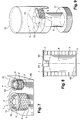
- FIG. 7 shows a variant in which a housing 50 of parallelepipedal shape such that a face 51 has two openings 52 and 53 for respectively receiving two wedging devices according to the invention 1 and 1 '.
- the flange 13 of the first device 1 bears against a rim defined around the first opening 52.
- this flange 13 may be fixed at a lower surface of this face 51.
- the introduction of the object P into the orifice 7 leads to the formation of the sleeve and to the wedging of this first object P in the housing 50.
- the second device 1 ' is by example of different dimensions to receive a different object P '.
- the object P 'and the second device 1' may be identical to the object P and to the device 1.
- housing 50 it is possible to design such a housing 50 to present several identical bottles for treatment to be staggered over time, or to propose packaging in the form of a box with different products, for example from the same range or from the same brand.
- the device 1 can also perform its function of protecting an object P, without the need for a holster or a complementary housing.
- the plate 2 in this variant embodiment is intended to cooperate with a operculum 60 after introduction of the object P into the device 1.
- the operculum 60 is for example folded, glued or slammed on the plate 2. It must have a resistance sufficient for an end 61 of the object P to bear against it, then that the opposite end 62 of this object P bears against the support 3, the connecting means 5 being then maintained in extension, in the form of a sleeve.
- the object P is intended to be mounted by the bottom in a housing 70.
- the object P is previously mounted in a cover 71 intended to cooperate with the open bottom of the housing 70.
- the flange 13 of the plate 2 is mounted inside the housing 70, integral with a relief 73 of an inner wall, away from the open bottom, of so that the cover 71 can also be introduced into the housing 70.
- the lid is slammed or screwed.
Landscapes
- Engineering & Computer Science (AREA)
- Mechanical Engineering (AREA)
- Buffer Packaging (AREA)
- Details Of Rigid Or Semi-Rigid Containers (AREA)
- Auxiliary Devices For And Details Of Packaging Control (AREA)
- Telephone Function (AREA)
- Vehicle Body Suspensions (AREA)
- Basic Packing Technique (AREA)
- Oscillators With Electromechanical Resonators (AREA)
- Massaging Devices (AREA)
Applications Claiming Priority (2)
| Application Number | Priority Date | Filing Date | Title |
|---|---|---|---|
| FR0350782A FR2861704B1 (fr) | 2003-11-04 | 2003-11-04 | Dispositif de calage |
| FR0350782 | 2003-11-04 |
Publications (2)
| Publication Number | Publication Date |
|---|---|
| EP1529740A1 true EP1529740A1 (de) | 2005-05-11 |
| EP1529740B1 EP1529740B1 (de) | 2008-08-13 |
Family
ID=34430077
Family Applications (1)
| Application Number | Title | Priority Date | Filing Date |
|---|---|---|---|
| EP04292618A Expired - Lifetime EP1529740B1 (de) | 2003-11-04 | 2004-11-04 | Halterungsvorrichtung |
Country Status (5)
| Country | Link |
|---|---|
| EP (1) | EP1529740B1 (de) |
| AT (1) | ATE404457T1 (de) |
| DE (1) | DE602004015702D1 (de) |
| ES (1) | ES2310705T3 (de) |
| FR (1) | FR2861704B1 (de) |
Cited By (1)
| Publication number | Priority date | Publication date | Assignee | Title |
|---|---|---|---|---|
| FR3117466A1 (fr) * | 2020-12-16 | 2022-06-17 | Atlantic Industrie | Emballage pour un produit, tel qu’un chauffe-eau |
Citations (2)
| Publication number | Priority date | Publication date | Assignee | Title |
|---|---|---|---|---|
| FR2571028A3 (fr) * | 1984-10-02 | 1986-04-04 | Idhexa | Manchon extensible pour le gainage d'objets de formes variees, en vue de leur protection, et application au conditionnement de ces objets |
| FR2635754A1 (fr) * | 1988-09-01 | 1990-03-02 | Baudet Daniel | Sac ou sachet a contenance variable |
-
2003
- 2003-11-04 FR FR0350782A patent/FR2861704B1/fr not_active Expired - Fee Related
-
2004
- 2004-11-04 AT AT04292618T patent/ATE404457T1/de not_active IP Right Cessation
- 2004-11-04 EP EP04292618A patent/EP1529740B1/de not_active Expired - Lifetime
- 2004-11-04 DE DE602004015702T patent/DE602004015702D1/de not_active Expired - Lifetime
- 2004-11-04 ES ES04292618T patent/ES2310705T3/es not_active Expired - Lifetime
Patent Citations (2)
| Publication number | Priority date | Publication date | Assignee | Title |
|---|---|---|---|---|
| FR2571028A3 (fr) * | 1984-10-02 | 1986-04-04 | Idhexa | Manchon extensible pour le gainage d'objets de formes variees, en vue de leur protection, et application au conditionnement de ces objets |
| FR2635754A1 (fr) * | 1988-09-01 | 1990-03-02 | Baudet Daniel | Sac ou sachet a contenance variable |
Cited By (1)
| Publication number | Priority date | Publication date | Assignee | Title |
|---|---|---|---|---|
| FR3117466A1 (fr) * | 2020-12-16 | 2022-06-17 | Atlantic Industrie | Emballage pour un produit, tel qu’un chauffe-eau |
Also Published As
| Publication number | Publication date |
|---|---|
| EP1529740B1 (de) | 2008-08-13 |
| DE602004015702D1 (de) | 2008-09-25 |
| ES2310705T3 (es) | 2009-01-16 |
| FR2861704A1 (fr) | 2005-05-06 |
| ATE404457T1 (de) | 2008-08-15 |
| FR2861704B1 (fr) | 2007-08-10 |
Similar Documents
| Publication | Publication Date | Title |
|---|---|---|
| FR2583330A1 (fr) | Article propre a constituer une etagere pliable pour tournevis et analogues; emballage contenant cette etagere | |
| FR2716163A1 (fr) | Emballages rapides et semi-automatiques obtenus à partir d'une feuille mince semi-rigide, plissée en double symétrie, principalement pour sandwichs cylindriques ou assimilés. | |
| US7571566B1 (en) | Container and method of use | |
| EP0691918B1 (de) | Schützende und festlegende verpackung zum verpacken eines brillenglases oder eines ähnlichen produktes | |
| EP1529740B1 (de) | Halterungsvorrichtung | |
| EP0543746B1 (de) | Schau-, Ausschmückungs- und Schutzbehälter für Topfpflanzen | |
| EP1787915B1 (de) | Flaschenbehälter | |
| CA2496701C (fr) | Dispositif pour la presentation et la conservation de bouquets de fleurs | |
| EP2173222A2 (de) | Vorrichtung zur anzeige und aufbewahrung von blumensträussen | |
| FR2721909A1 (fr) | Emballage individuel de protection et de calage notamment pour un verre de lunettes | |
| EP1140636B1 (de) | Vorgeformte verpackung für feste oder flüssige stoffe | |
| WO2002020372A1 (fr) | Dispositif d'emballage portable d'un bouquet de fleurs | |
| EP1809147B1 (de) | Vorrichtung zur präsentation von blumensträussen | |
| EP0454521A1 (de) | Vorrichtung zum Aufhängen von Artikeln auf einen Ständer und Verwendung der genannten Vorrichtung zum Tragen einer Verpackung und/oder eines verpackten Artikels | |
| FR3115027A1 (fr) | Boîte à œufs en carton | |
| FR2658787A1 (fr) | Barquette pour le conditionnement de produits fragiles. | |
| CN213058024U (zh) | 一种冰淇淋包装 | |
| FR2813289A1 (fr) | Contenant a calage pour au moins un objet fragile tel qu'une bouteille, notamment en vue d'expedition par poste ou messagerie | |
| EP0770553B1 (de) | Behälter für den Transport und das Zurschaustellen von Artikeln | |
| FR2778324A1 (fr) | Seau a fleurs en carton | |
| FR2658798A1 (fr) | Dispositif pour l'emballage d'une plante en pot. | |
| EP0799595B1 (de) | Behälter für ein entfaltbares oder abrollbares Band | |
| EP0541762A1 (de) | Verpackung bestehend aus einem flexibelen innenbeutel und einer steifen umhuellung and verfahren zur herstellung derselben | |
| FR2600307A1 (fr) | Emballage pour bouteilles couchees tete-beche | |
| FR2506729A1 (fr) | Emballage-presentoir pour produits en rouleaux |
Legal Events
| Date | Code | Title | Description |
|---|---|---|---|
| PUAI | Public reference made under article 153(3) epc to a published international application that has entered the european phase |
Free format text: ORIGINAL CODE: 0009012 |
|
| AK | Designated contracting states |
Kind code of ref document: A1 Designated state(s): AT BE BG CH CY CZ DE DK EE ES FI FR GB GR HU IE IS IT LI LU MC NL PL PT RO SE SI SK TR |
|
| AX | Request for extension of the european patent |
Extension state: AL HR LT LV MK YU |
|
| RIN1 | Information on inventor provided before grant (corrected) |
Inventor name: WINCKELS, MATHILDE |
|
| 17P | Request for examination filed |
Effective date: 20051111 |
|
| AKX | Designation fees paid |
Designated state(s): AT BE BG CH CY CZ DE DK EE ES FI FR GB GR HU IE IS IT LI LU MC NL PL PT RO SE SI SK TR |
|
| 17Q | First examination report despatched |
Effective date: 20070629 |
|
| GRAP | Despatch of communication of intention to grant a patent |
Free format text: ORIGINAL CODE: EPIDOSNIGR1 |
|
| GRAS | Grant fee paid |
Free format text: ORIGINAL CODE: EPIDOSNIGR3 |
|
| GRAA | (expected) grant |
Free format text: ORIGINAL CODE: 0009210 |
|
| AK | Designated contracting states |
Kind code of ref document: B1 Designated state(s): AT BE BG CH CY CZ DE DK EE ES FI FR GB GR HU IE IS IT LI LU MC NL PL PT RO SE SI SK TR |
|
| REG | Reference to a national code |
Ref country code: GB Ref legal event code: FG4D Free format text: NOT ENGLISH |
|
| REG | Reference to a national code |
Ref country code: CH Ref legal event code: EP |
|
| REG | Reference to a national code |
Ref country code: IE Ref legal event code: FG4D Free format text: LANGUAGE OF EP DOCUMENT: FRENCH |
|
| REF | Corresponds to: |
Ref document number: 602004015702 Country of ref document: DE Date of ref document: 20080925 Kind code of ref document: P |
|
| REG | Reference to a national code |
Ref country code: ES Ref legal event code: FG2A Ref document number: 2310705 Country of ref document: ES Kind code of ref document: T3 |
|
| PG25 | Lapsed in a contracting state [announced via postgrant information from national office to epo] |
Ref country code: NL Free format text: LAPSE BECAUSE OF FAILURE TO SUBMIT A TRANSLATION OF THE DESCRIPTION OR TO PAY THE FEE WITHIN THE PRESCRIBED TIME-LIMIT Effective date: 20080813 Ref country code: IS Free format text: LAPSE BECAUSE OF FAILURE TO SUBMIT A TRANSLATION OF THE DESCRIPTION OR TO PAY THE FEE WITHIN THE PRESCRIBED TIME-LIMIT Effective date: 20081213 |
|
| PG25 | Lapsed in a contracting state [announced via postgrant information from national office to epo] |
Ref country code: SI Free format text: LAPSE BECAUSE OF FAILURE TO SUBMIT A TRANSLATION OF THE DESCRIPTION OR TO PAY THE FEE WITHIN THE PRESCRIBED TIME-LIMIT Effective date: 20080813 Ref country code: FI Free format text: LAPSE BECAUSE OF FAILURE TO SUBMIT A TRANSLATION OF THE DESCRIPTION OR TO PAY THE FEE WITHIN THE PRESCRIBED TIME-LIMIT Effective date: 20080813 Ref country code: AT Free format text: LAPSE BECAUSE OF FAILURE TO SUBMIT A TRANSLATION OF THE DESCRIPTION OR TO PAY THE FEE WITHIN THE PRESCRIBED TIME-LIMIT Effective date: 20080813 |
|
| REG | Reference to a national code |
Ref country code: IE Ref legal event code: FD4D |
|
| PG25 | Lapsed in a contracting state [announced via postgrant information from national office to epo] |
Ref country code: DK Free format text: LAPSE BECAUSE OF FAILURE TO SUBMIT A TRANSLATION OF THE DESCRIPTION OR TO PAY THE FEE WITHIN THE PRESCRIBED TIME-LIMIT Effective date: 20080813 Ref country code: BG Free format text: LAPSE BECAUSE OF FAILURE TO SUBMIT A TRANSLATION OF THE DESCRIPTION OR TO PAY THE FEE WITHIN THE PRESCRIBED TIME-LIMIT Effective date: 20081113 Ref country code: IE Free format text: LAPSE BECAUSE OF FAILURE TO SUBMIT A TRANSLATION OF THE DESCRIPTION OR TO PAY THE FEE WITHIN THE PRESCRIBED TIME-LIMIT Effective date: 20080813 |
|
| PG25 | Lapsed in a contracting state [announced via postgrant information from national office to epo] |
Ref country code: PT Free format text: LAPSE BECAUSE OF FAILURE TO SUBMIT A TRANSLATION OF THE DESCRIPTION OR TO PAY THE FEE WITHIN THE PRESCRIBED TIME-LIMIT Effective date: 20090113 Ref country code: SK Free format text: LAPSE BECAUSE OF FAILURE TO SUBMIT A TRANSLATION OF THE DESCRIPTION OR TO PAY THE FEE WITHIN THE PRESCRIBED TIME-LIMIT Effective date: 20080813 Ref country code: CZ Free format text: LAPSE BECAUSE OF FAILURE TO SUBMIT A TRANSLATION OF THE DESCRIPTION OR TO PAY THE FEE WITHIN THE PRESCRIBED TIME-LIMIT Effective date: 20080813 Ref country code: RO Free format text: LAPSE BECAUSE OF FAILURE TO SUBMIT A TRANSLATION OF THE DESCRIPTION OR TO PAY THE FEE WITHIN THE PRESCRIBED TIME-LIMIT Effective date: 20080813 |
|
| BERE | Be: lapsed |
Owner name: L'OREAL Effective date: 20081130 |
|
| PLBE | No opposition filed within time limit |
Free format text: ORIGINAL CODE: 0009261 |
|
| STAA | Information on the status of an ep patent application or granted ep patent |
Free format text: STATUS: NO OPPOSITION FILED WITHIN TIME LIMIT |
|
| PG25 | Lapsed in a contracting state [announced via postgrant information from national office to epo] |
Ref country code: MC Free format text: LAPSE BECAUSE OF NON-PAYMENT OF DUE FEES Effective date: 20081130 |
|
| REG | Reference to a national code |
Ref country code: CH Ref legal event code: PL |
|
| 26N | No opposition filed |
Effective date: 20090514 |
|
| PG25 | Lapsed in a contracting state [announced via postgrant information from national office to epo] |
Ref country code: EE Free format text: LAPSE BECAUSE OF FAILURE TO SUBMIT A TRANSLATION OF THE DESCRIPTION OR TO PAY THE FEE WITHIN THE PRESCRIBED TIME-LIMIT Effective date: 20080813 |
|
| PG25 | Lapsed in a contracting state [announced via postgrant information from national office to epo] |
Ref country code: BE Free format text: LAPSE BECAUSE OF NON-PAYMENT OF DUE FEES Effective date: 20081130 |
|
| PG25 | Lapsed in a contracting state [announced via postgrant information from national office to epo] |
Ref country code: LI Free format text: LAPSE BECAUSE OF NON-PAYMENT OF DUE FEES Effective date: 20081130 Ref country code: CH Free format text: LAPSE BECAUSE OF NON-PAYMENT OF DUE FEES Effective date: 20081130 |
|
| PG25 | Lapsed in a contracting state [announced via postgrant information from national office to epo] |
Ref country code: SE Free format text: LAPSE BECAUSE OF FAILURE TO SUBMIT A TRANSLATION OF THE DESCRIPTION OR TO PAY THE FEE WITHIN THE PRESCRIBED TIME-LIMIT Effective date: 20081113 |
|
| PG25 | Lapsed in a contracting state [announced via postgrant information from national office to epo] |
Ref country code: PL Free format text: LAPSE BECAUSE OF FAILURE TO SUBMIT A TRANSLATION OF THE DESCRIPTION OR TO PAY THE FEE WITHIN THE PRESCRIBED TIME-LIMIT Effective date: 20080813 |
|
| PG25 | Lapsed in a contracting state [announced via postgrant information from national office to epo] |
Ref country code: CY Free format text: LAPSE BECAUSE OF FAILURE TO SUBMIT A TRANSLATION OF THE DESCRIPTION OR TO PAY THE FEE WITHIN THE PRESCRIBED TIME-LIMIT Effective date: 20080813 Ref country code: HU Free format text: LAPSE BECAUSE OF FAILURE TO SUBMIT A TRANSLATION OF THE DESCRIPTION OR TO PAY THE FEE WITHIN THE PRESCRIBED TIME-LIMIT Effective date: 20090214 Ref country code: LU Free format text: LAPSE BECAUSE OF NON-PAYMENT OF DUE FEES Effective date: 20081104 |
|
| PG25 | Lapsed in a contracting state [announced via postgrant information from national office to epo] |
Ref country code: TR Free format text: LAPSE BECAUSE OF FAILURE TO SUBMIT A TRANSLATION OF THE DESCRIPTION OR TO PAY THE FEE WITHIN THE PRESCRIBED TIME-LIMIT Effective date: 20080813 |
|
| PG25 | Lapsed in a contracting state [announced via postgrant information from national office to epo] |
Ref country code: GR Free format text: LAPSE BECAUSE OF FAILURE TO SUBMIT A TRANSLATION OF THE DESCRIPTION OR TO PAY THE FEE WITHIN THE PRESCRIBED TIME-LIMIT Effective date: 20081114 |
|
| PGFP | Annual fee paid to national office [announced via postgrant information from national office to epo] |
Ref country code: FR Payment date: 20101123 Year of fee payment: 7 |
|
| PGFP | Annual fee paid to national office [announced via postgrant information from national office to epo] |
Ref country code: DE Payment date: 20101027 Year of fee payment: 7 |
|
| PGFP | Annual fee paid to national office [announced via postgrant information from national office to epo] |
Ref country code: GB Payment date: 20101103 Year of fee payment: 7 Ref country code: IT Payment date: 20101111 Year of fee payment: 7 |
|
| PGFP | Annual fee paid to national office [announced via postgrant information from national office to epo] |
Ref country code: ES Payment date: 20101217 Year of fee payment: 7 |
|
| GBPC | Gb: european patent ceased through non-payment of renewal fee |
Effective date: 20111104 |
|
| REG | Reference to a national code |
Ref country code: FR Ref legal event code: ST Effective date: 20120731 |
|
| PG25 | Lapsed in a contracting state [announced via postgrant information from national office to epo] |
Ref country code: IT Free format text: LAPSE BECAUSE OF NON-PAYMENT OF DUE FEES Effective date: 20111104 |
|
| REG | Reference to a national code |
Ref country code: DE Ref legal event code: R119 Ref document number: 602004015702 Country of ref document: DE Effective date: 20120601 |
|
| PG25 | Lapsed in a contracting state [announced via postgrant information from national office to epo] |
Ref country code: GB Free format text: LAPSE BECAUSE OF NON-PAYMENT OF DUE FEES Effective date: 20111104 |
|
| PG25 | Lapsed in a contracting state [announced via postgrant information from national office to epo] |
Ref country code: FR Free format text: LAPSE BECAUSE OF NON-PAYMENT OF DUE FEES Effective date: 20111130 |
|
| REG | Reference to a national code |
Ref country code: ES Ref legal event code: FD2A Effective date: 20130603 |
|
| PG25 | Lapsed in a contracting state [announced via postgrant information from national office to epo] |
Ref country code: DE Free format text: LAPSE BECAUSE OF NON-PAYMENT OF DUE FEES Effective date: 20120601 |
|
| PG25 | Lapsed in a contracting state [announced via postgrant information from national office to epo] |
Ref country code: ES Free format text: LAPSE BECAUSE OF NON-PAYMENT OF DUE FEES Effective date: 20111105 |