EP1529587A1 - Maschinenreibwerkzeug, Wechselkopf und Schaft - Google Patents
Maschinenreibwerkzeug, Wechselkopf und Schaft Download PDFInfo
- Publication number
- EP1529587A1 EP1529587A1 EP03405791A EP03405791A EP1529587A1 EP 1529587 A1 EP1529587 A1 EP 1529587A1 EP 03405791 A EP03405791 A EP 03405791A EP 03405791 A EP03405791 A EP 03405791A EP 1529587 A1 EP1529587 A1 EP 1529587A1
- Authority
- EP
- European Patent Office
- Prior art keywords
- head
- shaft
- replaceable head
- replaceable
- recess
- Prior art date
- Legal status (The legal status is an assumption and is not a legal conclusion. Google has not performed a legal analysis and makes no representation as to the accuracy of the status listed.)
- Granted
Links
- 230000006978 adaptation Effects 0.000 claims description 4
- 239000002826 coolant Substances 0.000 abstract description 4
- 230000004308 accommodation Effects 0.000 abstract 1
- 239000011796 hollow space material Substances 0.000 abstract 1
- 238000004519 manufacturing process Methods 0.000 description 8
- 239000000463 material Substances 0.000 description 8
- 230000005540 biological transmission Effects 0.000 description 5
- 230000006835 compression Effects 0.000 description 2
- 238000007906 compression Methods 0.000 description 2
- 230000036346 tooth eruption Effects 0.000 description 2
- 239000003795 chemical substances by application Substances 0.000 description 1
- 239000002131 composite material Substances 0.000 description 1
- 238000010276 construction Methods 0.000 description 1
- 238000001816 cooling Methods 0.000 description 1
- 230000001419 dependent effect Effects 0.000 description 1
- 238000006073 displacement reaction Methods 0.000 description 1
- 238000005553 drilling Methods 0.000 description 1
- 210000004283 incisor Anatomy 0.000 description 1
- 238000003780 insertion Methods 0.000 description 1
- 230000037431 insertion Effects 0.000 description 1
- 238000003754 machining Methods 0.000 description 1
Images


Classifications
-
- B—PERFORMING OPERATIONS; TRANSPORTING
- B23—MACHINE TOOLS; METAL-WORKING NOT OTHERWISE PROVIDED FOR
- B23B—TURNING; BORING
- B23B31/00—Chucks; Expansion mandrels; Adaptations thereof for remote control
- B23B31/02—Chucks
- B23B31/10—Chucks characterised by the retaining or gripping devices or their immediate operating means
- B23B31/11—Retention by threaded connection
-
- B—PERFORMING OPERATIONS; TRANSPORTING
- B23—MACHINE TOOLS; METAL-WORKING NOT OTHERWISE PROVIDED FOR
- B23B—TURNING; BORING
- B23B29/00—Holders for non-rotary cutting tools; Boring bars or boring heads; Accessories for tool holders
- B23B29/03—Boring heads
-
- B—PERFORMING OPERATIONS; TRANSPORTING
- B23—MACHINE TOOLS; METAL-WORKING NOT OTHERWISE PROVIDED FOR
- B23B—TURNING; BORING
- B23B31/00—Chucks; Expansion mandrels; Adaptations thereof for remote control
- B23B31/02—Chucks
- B23B31/10—Chucks characterised by the retaining or gripping devices or their immediate operating means
- B23B31/11—Retention by threaded connection
- B23B31/1107—Retention by threaded connection for conical parts
- B23B31/1122—Retention by threaded connection for conical parts using cylindrical threads
-
- B—PERFORMING OPERATIONS; TRANSPORTING
- B23—MACHINE TOOLS; METAL-WORKING NOT OTHERWISE PROVIDED FOR
- B23D—PLANING; SLOTTING; SHEARING; BROACHING; SAWING; FILING; SCRAPING; LIKE OPERATIONS FOR WORKING METAL BY REMOVING MATERIAL, NOT OTHERWISE PROVIDED FOR
- B23D77/00—Reaming tools
-
- B—PERFORMING OPERATIONS; TRANSPORTING
- B23—MACHINE TOOLS; METAL-WORKING NOT OTHERWISE PROVIDED FOR
- B23D—PLANING; SLOTTING; SHEARING; BROACHING; SAWING; FILING; SCRAPING; LIKE OPERATIONS FOR WORKING METAL BY REMOVING MATERIAL, NOT OTHERWISE PROVIDED FOR
- B23D2277/00—Reaming tools
- B23D2277/02—Cutting head and shank made from two different components which are releasably or non-releasably attached to each other
-
- Y—GENERAL TAGGING OF NEW TECHNOLOGICAL DEVELOPMENTS; GENERAL TAGGING OF CROSS-SECTIONAL TECHNOLOGIES SPANNING OVER SEVERAL SECTIONS OF THE IPC; TECHNICAL SUBJECTS COVERED BY FORMER USPC CROSS-REFERENCE ART COLLECTIONS [XRACs] AND DIGESTS
- Y10—TECHNICAL SUBJECTS COVERED BY FORMER USPC
- Y10T—TECHNICAL SUBJECTS COVERED BY FORMER US CLASSIFICATION
- Y10T279/00—Chucks or sockets
- Y10T279/16—Longitudinal screw clamp
-
- Y—GENERAL TAGGING OF NEW TECHNOLOGICAL DEVELOPMENTS; GENERAL TAGGING OF CROSS-SECTIONAL TECHNOLOGIES SPANNING OVER SEVERAL SECTIONS OF THE IPC; TECHNICAL SUBJECTS COVERED BY FORMER USPC CROSS-REFERENCE ART COLLECTIONS [XRACs] AND DIGESTS
- Y10—TECHNICAL SUBJECTS COVERED BY FORMER USPC
- Y10T—TECHNICAL SUBJECTS COVERED BY FORMER US CLASSIFICATION
- Y10T29/00—Metal working
- Y10T29/49—Method of mechanical manufacture
- Y10T29/49995—Shaping one-piece blank by removing material
- Y10T29/49996—Successive distinct removal operations
-
- Y—GENERAL TAGGING OF NEW TECHNOLOGICAL DEVELOPMENTS; GENERAL TAGGING OF CROSS-SECTIONAL TECHNOLOGIES SPANNING OVER SEVERAL SECTIONS OF THE IPC; TECHNICAL SUBJECTS COVERED BY FORMER USPC CROSS-REFERENCE ART COLLECTIONS [XRACs] AND DIGESTS
- Y10—TECHNICAL SUBJECTS COVERED BY FORMER USPC
- Y10T—TECHNICAL SUBJECTS COVERED BY FORMER US CLASSIFICATION
- Y10T408/00—Cutting by use of rotating axially moving tool
- Y10T408/03—Processes
-
- Y—GENERAL TAGGING OF NEW TECHNOLOGICAL DEVELOPMENTS; GENERAL TAGGING OF CROSS-SECTIONAL TECHNOLOGIES SPANNING OVER SEVERAL SECTIONS OF THE IPC; TECHNICAL SUBJECTS COVERED BY FORMER USPC CROSS-REFERENCE ART COLLECTIONS [XRACs] AND DIGESTS
- Y10—TECHNICAL SUBJECTS COVERED BY FORMER USPC
- Y10T—TECHNICAL SUBJECTS COVERED BY FORMER US CLASSIFICATION
- Y10T408/00—Cutting by use of rotating axially moving tool
- Y10T408/89—Tool or Tool with support
- Y10T408/905—Having stepped cutting edges
- Y10T408/906—Axially spaced
-
- Y—GENERAL TAGGING OF NEW TECHNOLOGICAL DEVELOPMENTS; GENERAL TAGGING OF CROSS-SECTIONAL TECHNOLOGIES SPANNING OVER SEVERAL SECTIONS OF THE IPC; TECHNICAL SUBJECTS COVERED BY FORMER USPC CROSS-REFERENCE ART COLLECTIONS [XRACs] AND DIGESTS
- Y10—TECHNICAL SUBJECTS COVERED BY FORMER USPC
- Y10T—TECHNICAL SUBJECTS COVERED BY FORMER US CLASSIFICATION
- Y10T408/00—Cutting by use of rotating axially moving tool
- Y10T408/89—Tool or Tool with support
- Y10T408/909—Having peripherally spaced cutting edges
- Y10T408/9098—Having peripherally spaced cutting edges with means to retain Tool to support
- Y10T408/90993—Screw driven means
-
- Y—GENERAL TAGGING OF NEW TECHNOLOGICAL DEVELOPMENTS; GENERAL TAGGING OF CROSS-SECTIONAL TECHNOLOGIES SPANNING OVER SEVERAL SECTIONS OF THE IPC; TECHNICAL SUBJECTS COVERED BY FORMER USPC CROSS-REFERENCE ART COLLECTIONS [XRACs] AND DIGESTS
- Y10—TECHNICAL SUBJECTS COVERED BY FORMER USPC
- Y10T—TECHNICAL SUBJECTS COVERED BY FORMER US CLASSIFICATION
- Y10T408/00—Cutting by use of rotating axially moving tool
- Y10T408/94—Tool-support
- Y10T408/95—Tool-support with tool-retaining means
- Y10T408/957—Tool adapter
-
- Y—GENERAL TAGGING OF NEW TECHNOLOGICAL DEVELOPMENTS; GENERAL TAGGING OF CROSS-SECTIONAL TECHNOLOGIES SPANNING OVER SEVERAL SECTIONS OF THE IPC; TECHNICAL SUBJECTS COVERED BY FORMER USPC CROSS-REFERENCE ART COLLECTIONS [XRACs] AND DIGESTS
- Y10—TECHNICAL SUBJECTS COVERED BY FORMER USPC
- Y10T—TECHNICAL SUBJECTS COVERED BY FORMER US CLASSIFICATION
- Y10T409/00—Gear cutting, milling, or planing
- Y10T409/30—Milling
- Y10T409/309352—Cutter spindle or spindle support
- Y10T409/309408—Cutter spindle or spindle support with cutter holder
-
- Y—GENERAL TAGGING OF NEW TECHNOLOGICAL DEVELOPMENTS; GENERAL TAGGING OF CROSS-SECTIONAL TECHNOLOGIES SPANNING OVER SEVERAL SECTIONS OF THE IPC; TECHNICAL SUBJECTS COVERED BY FORMER USPC CROSS-REFERENCE ART COLLECTIONS [XRACs] AND DIGESTS
- Y10—TECHNICAL SUBJECTS COVERED BY FORMER USPC
- Y10T—TECHNICAL SUBJECTS COVERED BY FORMER US CLASSIFICATION
- Y10T409/00—Gear cutting, milling, or planing
- Y10T409/30—Milling
- Y10T409/30952—Milling with cutter holder
Definitions
- the invention relates to a machine tool, a replaceable head and a shaft for a machine tool according to the preamble of the claims 1, 9 and 14.
- Machine friction tools or machine reamers are used for fine machining of used cylindrical bores. Individual cutting edges each have a main cutting edge or bleed section and a minor cutting edge or leader.
- the Gating work accomplishes the Spanungsarbeit, the leading part serves the guidance of the Tool in the hole.
- the guide part in the axial direction many times longer than the gate section.
- the length of the guide section is thus for example 10 millimeters or more, with a diameter of for example about 15 millimeters.
- a machine reamer which has a main body and a replaceable head, that is, a replaceable rubbing head having.
- the friction head is integrally formed and has a rear plane surface in the axial direction protruding approach to change adaptation.
- This projecting approach is either pyramidal or cone shaped.
- In the Connection with the main body becomes the approach in a corresponding recess used the base body, with clamping straps, by separating gaps or are separated from each other or from the rest of the shaft by Dehnschlitze, expanded become.
- conical Connections additionally an external hexagon at the friction head and a corresponding one Hexagon socket formed on the body.
- US 1,472,798 shows a reaming head, in which a collar with the gate section and one part of the leading part is replaceable, while the rest of the leading part continues to be used.
- Another object of the invention is to provide a simplified To allow construction of said parts of a machine friction tool.
- the machine driving tool according to the invention has a friction head or replaceable head and a shaft according to the invention.
- h max (for D1 less than 12 mm) is at least 6 mm and (for D1 greater than 35 mm) at most 8 mm. In a preferred embodiment, h max is equal to 6 mm regardless of the diameter D1.
- a guide section on individual cutting the replaceable head is slightly shorter than h max .
- This embodiment of the replaceable head is based on the finding that a conventional, relatively long guide section of the cutting edge is not required in many applications. As a result, the replaceable head, even with smaller thicknesses, for example, under 5 mm, 4.5 mm, 4 mm, 3.5 mm, 3mm, 2.5mm or 2mm material-saving be made.
- the replaceable head in a plan shank side face as a connecting element a recess for centering attachment on the shaft.
- the shaft is preferably one-piece and has at an end face plane in the axial direction of this Flat surface protruding connecting lug, which with the recess of the Replaceable head corresponds.
- the replaceable head thus has no axially projecting Approach to the change adaptation. As a result, the material requirement at the replaceable head further reduced and simplifies the manufacture of the replaceable head.
- the replaceable head with two parallel, flat faces an axial distance of less than about 6, preferably less than 5 or less than or equal to 4 millimeters, and without one protruding beyond these faces Change adaptation.
- a flat shaft-side end face has a in the end face projecting recess or depression into which a corresponding, projecting part of the shaft is used. At this insertion this will Projection along its entire circumference or at least in three places compressed the exchange head or compressed or deformed inwards.
- the recess in the end face of the replaceable head an inner cone and according to the above approach on the shaft a corresponding outer cone.
- the dimensions of interior and outer cone are preferably matched to one another such that when placed of the replaceable head on the shaft, the frontal plane surface of the shaft and the opposite end face of the replaceable head a predetermined distance exhibit.
- To attach the replaceable head is at least one cap screw passed through at least one hole in the removable head and bolted in the shaft.
- the outer cone becomes of the shank compressed by the inner cone of the hard replaceable head, until the end face of the shaft and the opposite end of the Replaceable head meet. By the juxtaposition of these two End faces creates a frictional connection.
- the outer cone or the inner cone has a plurality, preferably three slightly protruding or cut segments on. These form at the composite Reaming tool Contact surfaces between shaft and exchangeable head and thus, for example, a three-point support. In the production only need made these segments and not the whole cone circumference with high accuracy, for example, be ground.
- in another embodiment of the invention is as a connecting element formed recess in the end face of the replaceable head substantially circular cylindrical and has at three points of the inner cylinder circumference in each case a support segment or a support point, in which the recess designed somewhat narrower is. These three locations are circumferentially spaced from each other distributed over the circumference. Accordingly, the trained as a connecting element protruding approach to the shaft also substantially circular cylindrical.
- the bearing segments become formed by flat surfaces.
- An extension of one of the support segments in the circumferential direction is comparatively larger than the extent of the other two, for example, one and a half times to twice as big.
- This overlay segment works as a driving segment.
- the driving segment also acts as an anti-rotation device:
- the orientation of the replaceable head during placement on the shaft is clearly defined as the driving segment corresponding must be oriented to the plane surface on the shaft.
- the driving segment causes a positive power transmission to the removable head and optionally by twisting a jamming of replaceable head and shaft.
- the replaceable head is analogous as described above by one or more preferably countersunk screws bolted to the shaft and to the front of the shaft pressed.
- the cylindrical shape of the connecting elements on the replaceable head and shaft allowed a simpler and cheaper production, with sufficient change accuracy the connection.
- the connecting elements in Replaceable head and shaft rounded polygon cylinder preferably triangular cylinder which are rounded along the circumference.
- the outer cylinder on the shaft is slightly smaller than the inner cylinder on the replaceable head, so that when putting on of the replaceable head on the shaft and a small mutual twisting three Form contact points on the circumference of the cylinder.
- the centering recess in the replaceable head is not in all embodiments Mandatory centered and continuous.
- the recess is arranged both centrally and axially in the interchangeable head and also throughout.
- the recess then forms on the End face of the replaceable head, which faces away from the shaft, a recess for the screw head.
- the screw head is retractable in the replaceable head.
- the processing depth in a blind hole is maximized.
- the shaft and the interchangeable head corresponding means for the unique orientation of the Replaceable head with respect to the shaft in the circumferential direction.
- the orientation agent on the replaceable head for example, a depression or a hole in the the shaft facing end face, and the corresponding orientation means on the shaft is a projection or a pin.
- the replaceable head has a plurality of spaced apart along its circumferential direction Cutting or cutting teeth on.
- Each cutting edge has a chamfered section and a leadership role.
- a chamfer preferably has in axial Direction a length of 0.03 mm to 1.2 mm, in particular from about 0.3 to 0.7 mm up.
- the remaining up to the thickness of the replaceable head length of the cutting edge forms the lead part.
- For an average length of the gating section of 0.5 mm and a replaceable head thickness of 4 mm results in a ratio between the length the gating part and the length of the leading part of 1: 7.
- this ratio is between 1: 6 and 1:10, which compares to large values the maximum usual values of for example 1:20 are.
- the big values result from the small thickness of the replaceable head. This in turn will be under Thanks to the realization possible that the greater part of all applications no particularly high demands on the leadership of the reamer.
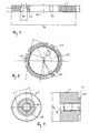
- FIG. 1 shows a longitudinal section through a head region of a machine driving tool according to the invention.
- a replaceable head 1 is by a centric in the axial direction extending head screw 3 screwed onto a shaft 2.
- the head screw 3 is recessed a recess for the screw head 14 of the cap screw 3.
- the replaceable head 1 For orientation of the replaceable head 1 in the circumferential direction, the replaceable head 1 an orientation hole 12 and the shaft 2 an orientation pin 22, the protrudes into the orientation hole 12.
- the shaft 2 has an axial bore 26, from which at the tool end coolant channels 24 to the outside of the Guide shaft 2 near the replaceable head 1. Due to the proximity of the coolant outlet to the replaceable head 1 and the small thickness h of the replaceable head is an improved Cooling of the cutting parts guaranteed.
- a shank plane surface 15 of the replaceable head 1 is through the screw to a frontal plane surface 25 of the shaft 2 pressed. It also fasteners, in the present Embodiment of the invention, an inner cone 11 of the replaceable head 1 and an outer cone 21 of the shaft 2, pressed against each other. Because the material of the replaceable head 1 has a lower deformability than that of the shaft 2, is doing the outer cone 21 in the radial direction within its material elasticity deformed inside and compressed or compacted.
- the replaceable head 1 has a diameter D1 between, for example, 10 mm and 60 mm, wherein for higher values an embodiment with a fastening of the replaceable head 1 according to FIG. 5 is preferred.
- the shaft 2 has a Diameter D2, which is at least a few millimeters smaller than that of Replaceable head 1.
- a thickness h of the replaceable head 1 in the axial direction, ie in the direction of the axis of rotation of the tool, is preferably less than 6 mm or 5 mm, in the present Example 4 mm, with a diameter D1 between 10 mm and 60 mm or more.
- the inner cone 11 protrudes, for example, to a depth of 2 mm in the Replaceable head 1 into it. Accordingly, the outer cone 21 protrudes about 2 mm above the end face 25 of the shaft 2 addition.
- the mass of inner cone 11 and Outer cone 21 are matched to each other, so that when loose assembly a predefined small air gap between the shaft-side plane surface 15 of the Replaceable head 1 and the frontal plane surface 25 of the shaft 2 is formed. While dressing the head screw 3, these surfaces are pressed together, and because of predetermined size of the air gap occurs a controlled, predetermined deformation the outer cone 21 on.
- FIG. 2 shows a longitudinal section through a head region of a shaft of a machine friction tool according to the invention.
- the shaft or at least the head area is preferably made in one piece.
- the axial bore 26 is continuous designed and has at the tool end a thread 23.
- the inner cone 11 has the axial bore 26 opposite the threaded bore 23 enlarged diameter. This leaves between the material the inner cone 11 and the cap screw 3 a free area for deformation the inner cone 11.
- the orientation pin 22 is pressed into a bore in the shaft 2.
- the orientation pin on the indexable insert 1 and the corresponding orientation hole may be disposed on the shaft 2. however This embodiment is slightly more expensive to manufacture, especially there Replaceable heads 1 more frequently than shafts 2 are replaced.
- FIG. 3 shows a shaft 2 according to the invention.
- the shaft 2 is machine side, So provided at his the tool 1 far end for clamping in a machine. He is for example of circular cylindrical shape or has standard clamping surfaces on. Exemplary masses are a shaft length of 80 mm and a Shank diameter D2 of 10 mm with reaming head diameters from 11 mm to 16 mm or a shaft length of 110 mm and a shaft diameter D2 of 16 mm Friction head diameters from 18 mm to 24 mm. It is preferably on the shaft itself no guide section designed to guide the shaft in the borehole.
- FIG. 4 shows an embodiment with a central head screw 3 according to FIGS. 1 to 3.
- a continuous recess 50,13,14 is the shaft side as a recess 50 respectively Inner cone 11 formed on the opposite side as a recess for the screw head 14, and in between as a bore 13th
- the replaceable head 1 has a plurality of circumferentially distributed incisors Cut 16 up.
- a cutting edge leads in the axial direction from a first to a second plane end face of the replaceable head 1.
- the end faces limit the Replaceable head 1 in the axial direction and perpendicular to the axial direction and at a distance h parallel to each other.
- a cutting edge 16 has a chamfered section 17 and a guide section 18.
- the leading part is comparatively short, so that the distance h is comparatively short. Despite the very short lead 18 is in most applications a convenient use of the machine friction tool possible according to the invention.
- FIG. 5 shows a preferred embodiment of the invention, in which several through holes, each with a recess for a screw head 14th are arranged concentrically around a central bore 13. This is also at such annular replaceable heads 1 with a larger diameter sufficient Mounting and torque transmission guaranteed.
- the recesses for the screw heads 14 and the connecting elements like inner cone 11 next to each other and not on the same axis can be arranged, the maximum thickness h1 even less than 3 mm or 2 mm be.
- FIG. 6 shows a further preferred embodiment of the invention, in which the inner cone 11 on three support segments 52, which are free, that is the remaining areas of the inner cone have a slightly larger inner radius.
- the support segments 52 are spaced from each other in the circumferential direction uniformly distributed over the circumference. During production, only the surfaces of these Pad segments 52 can be manufactured and ground with high accuracy.
- FIGS. 7 and 8 show sections through a replaceable head 1 in a further embodiment the invention.
- the connecting elements 27,50 substantially cylindrically shaped.
- FIG. 7 shows a cross section parallel to the axial direction and
- Figure 8 shows a section of a cross section perpendicular to the axial direction.
- a recess 50 acting as a connecting element is mainly shaped circular cylindrical, but has three support segments 51, 52. at Each support segment 51,52 is the inner wall of the circular cylinder over a sector of the circle plan. An extension of such a sector corresponds approximately to one Fifth to one-half of the cylinder diameter. With a cylinder diameter of about 17 mm, this corresponds for example to 2 mm to 4 mm.
- one of the bearing segments 52 in the circumferential direction substantially larger, for example twice as large as the others and thus acts as a driving segment 51.
- FIG. 9 shows corresponding sections through a shaft corresponding to FIG Replaceable head of Figures 7 and 8.
- the connecting element on the shaft 27 is in essentially cylindrical, with a plane worked sector, so a plan Surface on the shaft circumference 28.
- the connecting element is in the axial direction, for example by about 1 to 2 or 4 mm on the end face-end face 25 of the shaft 2 ago.
- FIG. 10 shows a detail with connecting elements of replaceable head and Shank according to another embodiment of the invention.
- the connecting element on the shaft 27 and corresponding to the recess 50 on the removable head. 1 shaped as rounded outer or inner triangular cylinder.
- the connecting element on the shaft 27 is slightly smaller than the recess 50, so that first a loose connection can be produced.
- FIG. 10 shows by way of illustration greatly exaggerated size difference.
Abstract
Description
- Figur 1
- einen Längsschnitt durch einen Kopfbereich eines Maschinenreibwerkzeugs gemäss der Erfindung;
- Figur 2
- einen Längsschnitt durch einen Kopfbereich eines Schafts eines Maschinenreibwerkzeugs gemäss der Erfindung;
- Figur 3
- einen Schaft gemäss der Erfindung;
- Figuren 4,5 und 6
- jeweils korrespondierende Ansichten von Wechselköpfen gemäss verschiedenen Ausführungsformen der Erfindung;
- Figuren 7 und 8
- Schnitte durch einen Wechselkopf in einer weiteren Ausführungsform der Erfindung;
- Figur 9
- korrespondierende Schnitte durch einen Schaft entsprechend dem Wechselkopf aus den Figuren 7 und 8; und
- Figur 10
- Verbindungselemente von Wechselkopf und Schaft in einer weiteren Ausführungsform der Erfindung.
- 1
- Reibkopf, Wechselkopf
- 11
- Innenkonus
- 12
- Orientierungsloch
- 13
- Bohrung
- 14
- Aussparung für Schraubenkopf
- 15
- schaftseitige Planfläche
- 16
- Schneide
- 17
- Anschnittpartie
- 18
- Führungspartie
- 2
- Schaft
- 21
- Aussenkonus
- 22
- Orientierungsstift
- 23
- Gewindebohrung
- 24
- Kühlmittelkanal
- 25
- stirnseitige Planfläche
- 26
- Axialbohrung
- 27
- Verbindungselement am Schaft
- 28
- plane Fläche am Schaftumfang
- 3
- Kopfschraube
- 50
- Aussparung
- 51
- Mitnahmesegment
- 52
- Auflagesegment
- 53
- Kontaktpunkt
Claims (16)
- Maschinenreibwerkzeug, aufweisend einen Schaft (2) und einen auswechselbaren, einstückigen Wechselkopf (1), dadurch gekennzeichnet, dass der Wechselkopf (1) in axialer Richtung an jeder Stelle, also inklusive von Mitteln zur Wechseladaption, dünner als eine maximale Dicke hmax ist, wobei sich diese maximale Dicke hmax in Millimetern aus einem Durchmesser D1 des Wechselkopfs in Millimetern berechnet als hmax = 6mm + (1/10)·(D1-12mm).
- Maschinenreibwerkzeug gemäss Anspruch 1, dadurch gekennzeichnet, dass der Wechselkopf (1) in einer planen schaftseitigen Stirnfläche (15) eine als Verbindungselement ausgebildete Aussparung (50) zur zentrierenden Befestigung des Wechselkopfs (1) auf dem Schaft (2) aufweist, und dass der Schaft (2) an einer stirnseitigen Planfläche (25) einen in axialer Richtung aus dieser Planfläche (25) hervortretenden Verbindungsansatz (21) aufweist, welcher mit der Aussparung (50) des Wechselkopfs (1) korrespondiert.
- Maschinenreibwerkzeug gemäss Anspruch 2, dadurch gekennzeichnet, dass der auf dem Schaft (2) montierte Wechselkopf (1) den Verbindungsansatz (21) des Schafts (2) zumindest stellenweise komprimiert.
- Maschinenreibwerkzeug gemäss Anspruch 3, dadurch gekennzeichnet, dass am Wechselkopf (1) die als Verbindungselement ausgebildete Aussparung (50) einen achsenzentralen Innenkonus (11) zur Zentrierung des Wechselkopfes (1) auf dem Schaft (2) bildet, und am Schaft (2) der Verbindungsansatz ein korrespondierender Aussenkonus (21) ist.
- Maschinenreibwerkzeug gemäss Anspruch 4, dass am Wechselkopf (1) der Innenkonus (11) mindestens drei freigestellte Auflagesegmente (52) aufweist.
- Maschinenreibwerkzeug gemäss Anspruch 2, dadurch gekennzeichnet; dass die als Verbindungselement ausgebildete Aussparung (50) in der Stirnfläche (15) des Wechselkopfs (1) zylindrisch ist, und dass der Wechselkopf (1) bei Montage auf dem Schaft (2) an drei Stellen (51,52;53) des Innenzylinderumfangs mit einem zylindrischen Verbindungselement (27) des Schafts (2) in Kontakt bringbar ist.
- Maschinenreibwerkzeug gemäss Anspruch 6, dadurch gekennzeichnet, dass die als Verbindungselement ausgebildete Aussparung (50) in der Stirnfläche (15) des Wechselkopfs (1) im wesentlichen kreiszylindrisch ist, und an drei Stellen des Innenzylinderumfangs jeweils ein Auflagesegment (51,52) oder einen Auflagepunkt aufweist, bei welchen die Aussparung (50) etwas enger ausgestaltet ist, und dass ein als Verbindungselement (27) ausgebildeter Teil des Schafts (2) im wesentlichen kreiszylindrisch ausgebildet ist.
- Maschinenreibwerkzeug gemäss Anspruch 7, dadurch gekennzeichnet, dass eine Ausdehnung eines der Auflagesegmente (51) in Umfangsrichtung vergleichsweise grösser als die Ausdehnung der beiden anderen Auflagesegmente (52) ist, insbesondere anderthalb mal bis doppelt so gross, und dass korrespondierend dazu der Schaft (1) auf einem Teilsektor des Umfangs eine plane Fläche (28) aufweist.
- Wechselkopf (1) für ein Maschinenreibwerkzeug, welcher Wechselkopf (1) einstückig ausgebildet ist, dadurch gekennzeichnet, dass der Wechselkopf (1) in axialer Richtung an jeder Stelle, also inklusive von Mitteln zur Wechseladaption, dünner als eine maximale Dicke hmax ist, wobei sich diese maximale Dicke hmax in Millimetern aus einem Durchmesser D1 des Wechselkopfs in Millimetern berechnet als hmax = 6 mm + (1/10)·(D1-12 mm).
- Wechselkopf (1) gemäss Anspruch 9, dadurch gekennzeichnet, dass der Wechselkopf (1) in axialer Richtung eine Dicke von maximal 6 mm, vorzugsweise maximal 4 mm oder weniger aufweist.
- Wechselkopf (1) gemäss Anspruch 9 oder 10, dadurch gekennzeichnet, dass der Wechselkopf (1) eine als Verbindungselement ausgebildete Aussparung (50) zur zentrierenden Befestigung des Wechselkopfs (1) auf einem Schaft (2) aufweist.
- Wechselkopf (1) gemäss einem der Ansprüche 9 bis 11, dadurch gekennzeichnet, dass er ein Mittel, insbesondere eine Aussparung (12), zur eindeutigen Orientierung des Wechselkopfes (1) in Umfangsrichtung aufweist.
- Wechselkopf (1) gemäss einem der Ansprüche 9 bis 12, dadurch gekennzeichnet, dass er mehrere durchgehende Bohrungen, mit jeweils einer Ausnehmung (14) zur Aufnahme eines Schraubenkopfes auf der dem Innenkonus gegenüberliegenden Seite aufweist.
- Schaft (2) für ein Maschinenreibwerkzeug, aufweisend einen im wesentlichen rotationssymmetrischen Schaft mit einer stirnseitigen Planfläche (25) dadurch gekennzeichnet, dass der Schaft (2) einen aus dieser Planfläche (25) hervortretenden Verbindungsansatz (21) zur Montage eines aufsetzbaren Wechselkopfs (1) aufweist.
- Schaft (2) gemäss Anspruch 14, dadurch gekennzeichnet, dass der Verbindungsansatz ein Aussenkonus (21) ist.
- Schaft (2) gemäss einem der Ansprüche 14 oder 15, dadurch gekennzeichnet, dass er auf der stirnseitigen Planfläche (25) ein Mittel (22) zur eindeutigen Orientierung eines aufsetzbaren Wechselkopfes (1) in Umfangsrichtung aufweist.
Priority Applications (8)
| Application Number | Priority Date | Filing Date | Title |
|---|---|---|---|
| ES03405791T ES2297113T3 (es) | 2003-11-06 | 2003-11-06 | Maquina herramienta de friccion; cabezal de sustitucion y mango. |
| EP03405791A EP1529587B1 (de) | 2003-11-06 | 2003-11-06 | Maschinenreibwerkzeug, Wechselkopf und Schaft |
| DE50308700T DE50308700D1 (de) | 2003-11-06 | 2003-11-06 | Maschinenreibwerkzeug, Wechselkopf und Schaft |
| US10/595,700 US7748934B2 (en) | 2003-11-06 | 2004-11-05 | Machine friction tool, interchangeable head and shaft |
| CN200480039589.0A CN1902019B (zh) | 2003-11-06 | 2004-11-05 | 机床铰孔工具以及用于机床铰孔工具的可互换头和轴 |
| JP2006537035A JP4977468B2 (ja) | 2003-11-06 | 2004-11-05 | 機械リーマ工具 |
| PCT/CH2004/000671 WO2005044498A1 (de) | 2003-11-06 | 2004-11-05 | Maschinenreibwerkzeug, wechselkopf und schaft |
| JP2011255147A JP2012061594A (ja) | 2003-11-06 | 2011-11-22 | 機械リーマ工具、交換ヘッド及びシャフト |
Applications Claiming Priority (1)
| Application Number | Priority Date | Filing Date | Title |
|---|---|---|---|
| EP03405791A EP1529587B1 (de) | 2003-11-06 | 2003-11-06 | Maschinenreibwerkzeug, Wechselkopf und Schaft |
Publications (2)
| Publication Number | Publication Date |
|---|---|
| EP1529587A1 true EP1529587A1 (de) | 2005-05-11 |
| EP1529587B1 EP1529587B1 (de) | 2007-11-28 |
Family
ID=34429609
Family Applications (1)
| Application Number | Title | Priority Date | Filing Date |
|---|---|---|---|
| EP03405791A Expired - Lifetime EP1529587B1 (de) | 2003-11-06 | 2003-11-06 | Maschinenreibwerkzeug, Wechselkopf und Schaft |
Country Status (7)
| Country | Link |
|---|---|
| US (1) | US7748934B2 (de) |
| EP (1) | EP1529587B1 (de) |
| JP (2) | JP4977468B2 (de) |
| CN (1) | CN1902019B (de) |
| DE (1) | DE50308700D1 (de) |
| ES (1) | ES2297113T3 (de) |
| WO (1) | WO2005044498A1 (de) |
Cited By (4)
| Publication number | Priority date | Publication date | Assignee | Title |
|---|---|---|---|---|
| US7189039B2 (en) * | 2002-01-29 | 2007-03-13 | Sandvik Intellectual Property Ab | Tool coupling for rotating tools |
| WO2010149699A1 (de) | 2009-06-24 | 2010-12-29 | Johne + Co. Präzisionswerkzeuge Gmbh | Wechselkopfhalter, werkzeugkopf und verfahren |
| WO2011032921A1 (de) | 2009-09-16 | 2011-03-24 | Hartmetall-Werkzeugfabrik Paul Horn Gmbh | Reibwerkzeug zur spanenden bearbeitung eines werkstücks |
| DE102014209135B3 (de) * | 2014-05-14 | 2015-11-05 | Kennametal Inc. | Werkzeugkopf und Rotationswerkzeug mit einem solchen |
Families Citing this family (13)
| Publication number | Priority date | Publication date | Assignee | Title |
|---|---|---|---|---|
| US8360699B2 (en) * | 2007-01-04 | 2013-01-29 | Stojan Stojanovski | Cutting tool assembly with an eccentric drive member |
| US8517644B2 (en) * | 2007-06-07 | 2013-08-27 | Allied Machine & Engineering Corporation | Adjustable indexable drill and modular system and holder |
| US9004827B2 (en) | 2007-06-07 | 2015-04-14 | Allied Machine & Engineering Corp. | Adjustable indexable drill and modular system and holder |
| RU2547365C2 (ru) * | 2007-06-07 | 2015-04-10 | Вмакс, Инк. | Регулируемое сверло с механическим креплением многогранных режущих пластин |
| US8506212B2 (en) * | 2007-06-07 | 2013-08-13 | Allied Machine & Engineering Corporation | Adjustable indexable drill |
| JP4967863B2 (ja) * | 2007-07-05 | 2012-07-04 | 三菱マテリアル株式会社 | 穴加工工具 |
| DE102008040563A1 (de) * | 2008-07-18 | 2010-01-21 | Sandvik Intellectual Property Ab | Werkzeug mit Befestigungseinrichtung |
| DE102010018254B4 (de) * | 2010-04-23 | 2022-11-10 | Kennametal Inc. | Kühlmittelverteiler |
| DE102010054392A1 (de) * | 2010-12-07 | 2012-06-14 | Hartmetall-Werkzeugfabrik Paul Horn Gmbh | Schneidwerkzeug zur spanenden Bearbeitung eines Werkzeugs |
| US8827610B2 (en) * | 2011-08-05 | 2014-09-09 | Kennametal Inc. | Hydraulic coupling system for coupling a shell mill to an adapter |
| CN102554327A (zh) * | 2012-01-05 | 2012-07-11 | 哈尔滨飞机工业集团有限责任公司 | 一种可排碎屑的盘式蜂窝铣刀 |
| CH710710A1 (de) * | 2015-02-11 | 2016-08-15 | Urma Ag | Maschinenreibwerkzeug mit einem Schaft und einem darauf montierten Wechselkopf, sowie Wechselkopf und Schaft für ein Maschinenreibwerkzeug. |
| US20200254545A1 (en) * | 2019-02-08 | 2020-08-13 | Kennametal Inc. | One-piece reamer cutting discs and tool bodies |
Citations (7)
| Publication number | Priority date | Publication date | Assignee | Title |
|---|---|---|---|---|
| US2164573A (en) * | 1936-12-21 | 1939-07-04 | Packard Motor Car Co | Tool |
| US2164571A (en) * | 1936-11-17 | 1939-07-04 | Packard Motor Car Co | Cutting tool |
| US2303487A (en) * | 1939-05-08 | 1942-12-01 | Frank P Miller | Reamer |
| US3087360A (en) * | 1960-07-19 | 1963-04-30 | Waldo L Garberding | Cutting tool having universal joint |
| US4166711A (en) * | 1977-01-22 | 1979-09-04 | Mapal Fabrik Fur Prazisionswerkzeuge Dr. Kress Kg | Chucking reamer with replaceable cutter |
| US5163790A (en) * | 1991-03-13 | 1992-11-17 | Polytool Ag | Reamer with interchangeable cutter head |
| JPH0740141A (ja) * | 1993-07-30 | 1995-02-10 | Riide Giken Kk | リーマ |
Family Cites Families (26)
| Publication number | Priority date | Publication date | Assignee | Title |
|---|---|---|---|---|
| US1032764A (en) * | 1911-03-13 | 1912-07-16 | William H Nichols | Thread-gage. |
| US1472798A (en) | 1920-12-27 | 1923-11-06 | Standard Reamer & Tool Company | Reamer |
| US1797296A (en) * | 1924-05-05 | 1931-03-24 | United Shoe Machinery Corp | Cutter holder |
| US2164572A (en) | 1936-12-10 | 1939-07-04 | Packard Motor Car Co | Tool |
| US2369273A (en) * | 1943-03-23 | 1945-02-13 | Harding F Bakewell | Rotary cutting tool |
| US2912904A (en) * | 1955-10-31 | 1959-11-17 | William P Peterson | Milling machine arbor |
| US2937575A (en) * | 1956-10-15 | 1960-05-24 | Snyder Tool & Engineering Co | Milling cutter |
| US3041898A (en) * | 1958-01-09 | 1962-07-03 | Scully Jones & Co | Tool centering device |
| CH433916A (de) | 1966-04-15 | 1967-04-15 | Merz Ag | Feste Reibahle mit Hartmetallschneiden |
| CH599820A5 (de) * | 1977-02-03 | 1978-05-31 | Dixi Sa | |
| JPH05345221A (ja) | 1992-06-15 | 1993-12-27 | Hitachi Tool Eng Ltd | コーティングリーマ |
| DE4239311C2 (de) * | 1992-11-23 | 1996-04-18 | Guehring Joerg Dr | Bohrer, insbesondere Spitzbohrwerkzeug mit austauschbarem Schneideinsatz |
| JPH08507003A (ja) * | 1993-04-14 | 1996-07-30 | ツェトル.ゲゼルシャフト.ミット.ベシュレンクテル.ハフツング.ツェーエヌツェー.プレツィシオンズ−ウント.ゾンデルウエルクツオイグ | フライス工具 |
| DE19600239C1 (de) * | 1996-01-05 | 1997-04-10 | Ima Maschinenfabriken Klessmann Gmbh | Bearbeitungsaggregat für Werkstücke aus Holz und/oder Holzaustauschstoffen |
| JP3635789B2 (ja) * | 1996-06-26 | 2005-04-06 | 住友電気工業株式会社 | 回転切削工具 |
| JPH10249624A (ja) * | 1997-01-10 | 1998-09-22 | Mitsubishi Materials Corp | 刃部交換式エンドミル |
| US5873687A (en) * | 1997-04-16 | 1999-02-23 | Mori Seiki Co., Ltd. | Tool unit with hydraulic feed passage |
| JPH10309616A (ja) * | 1997-05-09 | 1998-11-24 | Mitsubishi Materials Corp | 刃部交換式エンドミル |
| JPH11129116A (ja) | 1997-10-28 | 1999-05-18 | Honda Motor Co Ltd | リーマーおよびその使用方法 |
| EP1090705A3 (de) * | 1999-10-04 | 2001-04-25 | Peter Baumgärtner | Werkzeugdorn, insbesondere Fräs- oder Sägedorn |
| DE10009721A1 (de) * | 2000-03-01 | 2001-09-06 | Komet Stahlhalter Werkzeuge | Maschinenreibahle und Reibkopf für eine Maschinenreibahle |
| DE10009728A1 (de) * | 2000-03-01 | 2001-09-06 | Dihart Ag Dulliken | Reibwerkzeug mit Führungsschaft |
| JP4394269B2 (ja) * | 2000-06-06 | 2010-01-06 | 富士精工株式会社 | 加工工具 |
| US6547495B2 (en) * | 2001-01-29 | 2003-04-15 | General Electric Company | Method for reaming hole and improved reamer |
| DE20119569U1 (de) | 2001-12-01 | 2002-02-14 | Ake Knebel Gmbh & Co | Vorrichtung zur Aufnahme von Werkzeugen |
| DE202004009549U1 (de) | 2004-06-11 | 2004-08-12 | Hermann Bilz Gmbh & Co. Kg | Reibwerkzeug |
-
2003
- 2003-11-06 EP EP03405791A patent/EP1529587B1/de not_active Expired - Lifetime
- 2003-11-06 ES ES03405791T patent/ES2297113T3/es not_active Expired - Lifetime
- 2003-11-06 DE DE50308700T patent/DE50308700D1/de not_active Expired - Lifetime
-
2004
- 2004-11-05 CN CN200480039589.0A patent/CN1902019B/zh active Active
- 2004-11-05 WO PCT/CH2004/000671 patent/WO2005044498A1/de active Application Filing
- 2004-11-05 JP JP2006537035A patent/JP4977468B2/ja active Active
- 2004-11-05 US US10/595,700 patent/US7748934B2/en active Active
-
2011
- 2011-11-22 JP JP2011255147A patent/JP2012061594A/ja active Pending
Patent Citations (7)
| Publication number | Priority date | Publication date | Assignee | Title |
|---|---|---|---|---|
| US2164571A (en) * | 1936-11-17 | 1939-07-04 | Packard Motor Car Co | Cutting tool |
| US2164573A (en) * | 1936-12-21 | 1939-07-04 | Packard Motor Car Co | Tool |
| US2303487A (en) * | 1939-05-08 | 1942-12-01 | Frank P Miller | Reamer |
| US3087360A (en) * | 1960-07-19 | 1963-04-30 | Waldo L Garberding | Cutting tool having universal joint |
| US4166711A (en) * | 1977-01-22 | 1979-09-04 | Mapal Fabrik Fur Prazisionswerkzeuge Dr. Kress Kg | Chucking reamer with replaceable cutter |
| US5163790A (en) * | 1991-03-13 | 1992-11-17 | Polytool Ag | Reamer with interchangeable cutter head |
| JPH0740141A (ja) * | 1993-07-30 | 1995-02-10 | Riide Giken Kk | リーマ |
Non-Patent Citations (1)
| Title |
|---|
| PATENT ABSTRACTS OF JAPAN vol. 1995, no. 05 30 June 1995 (1995-06-30) * |
Cited By (8)
| Publication number | Priority date | Publication date | Assignee | Title |
|---|---|---|---|---|
| US7189039B2 (en) * | 2002-01-29 | 2007-03-13 | Sandvik Intellectual Property Ab | Tool coupling for rotating tools |
| WO2010149699A1 (de) | 2009-06-24 | 2010-12-29 | Johne + Co. Präzisionswerkzeuge Gmbh | Wechselkopfhalter, werkzeugkopf und verfahren |
| EP2851147A3 (de) * | 2009-06-24 | 2015-08-12 | Johne + Co. Präzisionswerkzeuge GmbH | Wechselkopfhalter, Werkzeugkopf und verfahren |
| DE102009030470B4 (de) * | 2009-06-24 | 2015-12-24 | Johne & Co. Präzisionswerkzeuge GmbH | Wechselkopfhalter-System und Werkzeugkopfelement |
| WO2011032921A1 (de) | 2009-09-16 | 2011-03-24 | Hartmetall-Werkzeugfabrik Paul Horn Gmbh | Reibwerkzeug zur spanenden bearbeitung eines werkstücks |
| DE102009042395A1 (de) | 2009-09-16 | 2011-03-24 | Hartmetall-Werkzeugfabrik Paul Horn Gmbh | Reibwerkzeug zur spanenden Bearbeitung eines Werkstücks |
| DE102014209135B3 (de) * | 2014-05-14 | 2015-11-05 | Kennametal Inc. | Werkzeugkopf und Rotationswerkzeug mit einem solchen |
| US10160050B2 (en) | 2014-05-14 | 2018-12-25 | Kennametal, Inc. | Reaming head interface |
Also Published As
| Publication number | Publication date |
|---|---|
| ES2297113T3 (es) | 2008-05-01 |
| WO2005044498A1 (de) | 2005-05-19 |
| CN1902019B (zh) | 2010-12-22 |
| JP4977468B2 (ja) | 2012-07-18 |
| JP2012061594A (ja) | 2012-03-29 |
| DE50308700D1 (de) | 2008-01-10 |
| CN1902019A (zh) | 2007-01-24 |
| US7748934B2 (en) | 2010-07-06 |
| US20070067979A1 (en) | 2007-03-29 |
| JP2007509762A (ja) | 2007-04-19 |
| EP1529587B1 (de) | 2007-11-28 |
Similar Documents
| Publication | Publication Date | Title |
|---|---|---|
| EP1265723B1 (de) | Maschinenreibahle und reibkopf für eine maschinenreibahle | |
| EP1100642B1 (de) | Bohrwerkzeug mit einem gegen lösen gesicherten, austauschbaren schneideinsatz | |
| DE102005014422B4 (de) | Bohrgewindefräser | |
| EP1529587A1 (de) | Maschinenreibwerkzeug, Wechselkopf und Schaft | |
| EP1474258B1 (de) | Maschinenreibahle | |
| EP3463729B1 (de) | Drehwerkzeug mit austauschbaren schneideinsätzen | |
| DE202012100353U1 (de) | Werkzeughalterung zur Montage eines Meißelwerkzeugs | |
| EP2388098B1 (de) | Dehnreibahle | |
| DE102005031683A1 (de) | Maschinenwerkzeug | |
| DE2145795A1 (de) | Schneidwerkzeug | |
| EP1864741B1 (de) | Werkzeug für die Bearbeitung eines Werkstücks | |
| DE112014000529T5 (de) | Bohrerwendeschneidplatte und Drehschneidwerkzeug, das diese verwendet | |
| EP1646470A1 (de) | Schnittstelle zwischen zwei teilelementen eines werkzeugsystems | |
| EP2300183A1 (de) | Ausbohrwerkzeug | |
| EP3150315A1 (de) | Schaftfräser | |
| DE2056091C3 (de) | Spitzbohrwerkzeug | |
| WO2010006966A1 (de) | Werkzeug mit befestigungseinrichtung | |
| EP1706654B1 (de) | Gewindering | |
| DE2434041B2 (de) | Verstellbare mehrmesser-maschinenreibahle | |
| DE102010006918A1 (de) | Verbindungssystem zum lösbaren Verbinden zweier Bauteile | |
| DE102017127814A1 (de) | Werkzeug zur spanenden Bearbeitung eines Werkstücks | |
| DE19710996C2 (de) | Bohrwerkzeug, insbesondere für Bohrungen in Vollmaterial oder zum Aufbohren | |
| EP2464479B1 (de) | Fräswerkzeug, insbesondere gewindefräswerkzeug | |
| EP3256282A1 (de) | Maschinenreibwerkzeug, wechselkopf und schaft für ein maschinenreibwerkzeug | |
| DE102005019426B4 (de) | Werkzeug zur Erzeugung oder Nachbereitung eines Gewindes, insbesondere eines Innengewindes |
Legal Events
| Date | Code | Title | Description |
|---|---|---|---|
| PUAI | Public reference made under article 153(3) epc to a published international application that has entered the european phase |
Free format text: ORIGINAL CODE: 0009012 |
|
| 17P | Request for examination filed |
Effective date: 20031108 |
|
| AK | Designated contracting states |
Kind code of ref document: A1 Designated state(s): AT BE BG CH CY CZ DE DK EE ES FI FR GB GR HU IE IT LI LU MC NL PT RO SE SI SK TR |
|
| AX | Request for extension of the european patent |
Extension state: AL LT LV MK |
|
| AKX | Designation fees paid |
Designated state(s): AT BE BG CH CY CZ DE DK EE ES FI FR GB GR HU IE IT LI LU MC NL PT RO SE SI SK TR |
|
| 17Q | First examination report despatched |
Effective date: 20060317 |
|
| GRAP | Despatch of communication of intention to grant a patent |
Free format text: ORIGINAL CODE: EPIDOSNIGR1 |
|
| GRAS | Grant fee paid |
Free format text: ORIGINAL CODE: EPIDOSNIGR3 |
|
| GRAA | (expected) grant |
Free format text: ORIGINAL CODE: 0009210 |
|
| AK | Designated contracting states |
Kind code of ref document: B1 Designated state(s): AT BE BG CH CY CZ DE DK EE ES FI FR GB GR HU IE IT LI LU MC NL PT RO SE SI SK TR |
|
| REG | Reference to a national code |
Ref country code: GB Ref legal event code: FG4D Free format text: NOT ENGLISH |
|
| REG | Reference to a national code |
Ref country code: IE Ref legal event code: FG4D Free format text: LANGUAGE OF EP DOCUMENT: GERMAN |
|
| REG | Reference to a national code |
Ref country code: CH Ref legal event code: EP |
|
| REF | Corresponds to: |
Ref document number: 50308700 Country of ref document: DE Date of ref document: 20080110 Kind code of ref document: P |
|
| REG | Reference to a national code |
Ref country code: CH Ref legal event code: NV Representative=s name: FREI PATENTANWALTSBUERO AG |
|
| PG25 | Lapsed in a contracting state [announced via postgrant information from national office to epo] |
Ref country code: NL Free format text: LAPSE BECAUSE OF FAILURE TO SUBMIT A TRANSLATION OF THE DESCRIPTION OR TO PAY THE FEE WITHIN THE PRESCRIBED TIME-LIMIT Effective date: 20071128 Ref country code: SE Free format text: LAPSE BECAUSE OF FAILURE TO SUBMIT A TRANSLATION OF THE DESCRIPTION OR TO PAY THE FEE WITHIN THE PRESCRIBED TIME-LIMIT Effective date: 20080228 |
|
| NLV1 | Nl: lapsed or annulled due to failure to fulfill the requirements of art. 29p and 29m of the patents act | ||
| REG | Reference to a national code |
Ref country code: ES Ref legal event code: FG2A Ref document number: 2297113 Country of ref document: ES Kind code of ref document: T3 |
|
| PG25 | Lapsed in a contracting state [announced via postgrant information from national office to epo] |
Ref country code: SI Free format text: LAPSE BECAUSE OF FAILURE TO SUBMIT A TRANSLATION OF THE DESCRIPTION OR TO PAY THE FEE WITHIN THE PRESCRIBED TIME-LIMIT Effective date: 20071128 Ref country code: FI Free format text: LAPSE BECAUSE OF FAILURE TO SUBMIT A TRANSLATION OF THE DESCRIPTION OR TO PAY THE FEE WITHIN THE PRESCRIBED TIME-LIMIT Effective date: 20071128 Ref country code: BG Free format text: LAPSE BECAUSE OF FAILURE TO SUBMIT A TRANSLATION OF THE DESCRIPTION OR TO PAY THE FEE WITHIN THE PRESCRIBED TIME-LIMIT Effective date: 20080228 |
|
| GBV | Gb: ep patent (uk) treated as always having been void in accordance with gb section 77(7)/1977 [no translation filed] | ||
| PG25 | Lapsed in a contracting state [announced via postgrant information from national office to epo] |
Ref country code: DK Free format text: LAPSE BECAUSE OF FAILURE TO SUBMIT A TRANSLATION OF THE DESCRIPTION OR TO PAY THE FEE WITHIN THE PRESCRIBED TIME-LIMIT Effective date: 20071128 Ref country code: CZ Free format text: LAPSE BECAUSE OF FAILURE TO SUBMIT A TRANSLATION OF THE DESCRIPTION OR TO PAY THE FEE WITHIN THE PRESCRIBED TIME-LIMIT Effective date: 20071128 |
|
| ET | Fr: translation filed | ||
| PG25 | Lapsed in a contracting state [announced via postgrant information from national office to epo] |
Ref country code: SK Free format text: LAPSE BECAUSE OF FAILURE TO SUBMIT A TRANSLATION OF THE DESCRIPTION OR TO PAY THE FEE WITHIN THE PRESCRIBED TIME-LIMIT Effective date: 20071128 Ref country code: RO Free format text: LAPSE BECAUSE OF FAILURE TO SUBMIT A TRANSLATION OF THE DESCRIPTION OR TO PAY THE FEE WITHIN THE PRESCRIBED TIME-LIMIT Effective date: 20071128 |
|
| PG25 | Lapsed in a contracting state [announced via postgrant information from national office to epo] |
Ref country code: PT Free format text: LAPSE BECAUSE OF FAILURE TO SUBMIT A TRANSLATION OF THE DESCRIPTION OR TO PAY THE FEE WITHIN THE PRESCRIBED TIME-LIMIT Effective date: 20080428 |
|
| REG | Reference to a national code |
Ref country code: IE Ref legal event code: FD4D |
|
| PLBE | No opposition filed within time limit |
Free format text: ORIGINAL CODE: 0009261 |
|
| STAA | Information on the status of an ep patent application or granted ep patent |
Free format text: STATUS: NO OPPOSITION FILED WITHIN TIME LIMIT |
|
| PG25 | Lapsed in a contracting state [announced via postgrant information from national office to epo] |
Ref country code: IE Free format text: LAPSE BECAUSE OF FAILURE TO SUBMIT A TRANSLATION OF THE DESCRIPTION OR TO PAY THE FEE WITHIN THE PRESCRIBED TIME-LIMIT Effective date: 20071128 |
|
| 26N | No opposition filed |
Effective date: 20080829 |
|
| PG25 | Lapsed in a contracting state [announced via postgrant information from national office to epo] |
Ref country code: GB Free format text: LAPSE BECAUSE OF FAILURE TO SUBMIT A TRANSLATION OF THE DESCRIPTION OR TO PAY THE FEE WITHIN THE PRESCRIBED TIME-LIMIT Effective date: 20071128 |
|
| PG25 | Lapsed in a contracting state [announced via postgrant information from national office to epo] |
Ref country code: GR Free format text: LAPSE BECAUSE OF FAILURE TO SUBMIT A TRANSLATION OF THE DESCRIPTION OR TO PAY THE FEE WITHIN THE PRESCRIBED TIME-LIMIT Effective date: 20080229 |
|
| PG25 | Lapsed in a contracting state [announced via postgrant information from national office to epo] |
Ref country code: EE Free format text: LAPSE BECAUSE OF FAILURE TO SUBMIT A TRANSLATION OF THE DESCRIPTION OR TO PAY THE FEE WITHIN THE PRESCRIBED TIME-LIMIT Effective date: 20071128 |
|
| BERE | Be: lapsed |
Owner name: URMA A.G. Effective date: 20081130 |
|
| PG25 | Lapsed in a contracting state [announced via postgrant information from national office to epo] |
Ref country code: MC Free format text: LAPSE BECAUSE OF NON-PAYMENT OF DUE FEES Effective date: 20081130 |
|
| PG25 | Lapsed in a contracting state [announced via postgrant information from national office to epo] |
Ref country code: CY Free format text: LAPSE BECAUSE OF FAILURE TO SUBMIT A TRANSLATION OF THE DESCRIPTION OR TO PAY THE FEE WITHIN THE PRESCRIBED TIME-LIMIT Effective date: 20071128 |
|
| PG25 | Lapsed in a contracting state [announced via postgrant information from national office to epo] |
Ref country code: BE Free format text: LAPSE BECAUSE OF NON-PAYMENT OF DUE FEES Effective date: 20081130 |
|
| PG25 | Lapsed in a contracting state [announced via postgrant information from national office to epo] |
Ref country code: AT Free format text: LAPSE BECAUSE OF NON-PAYMENT OF DUE FEES Effective date: 20081106 |
|
| PG25 | Lapsed in a contracting state [announced via postgrant information from national office to epo] |
Ref country code: HU Free format text: LAPSE BECAUSE OF FAILURE TO SUBMIT A TRANSLATION OF THE DESCRIPTION OR TO PAY THE FEE WITHIN THE PRESCRIBED TIME-LIMIT Effective date: 20080529 Ref country code: LU Free format text: LAPSE BECAUSE OF NON-PAYMENT OF DUE FEES Effective date: 20081106 |
|
| PG25 | Lapsed in a contracting state [announced via postgrant information from national office to epo] |
Ref country code: TR Free format text: LAPSE BECAUSE OF FAILURE TO SUBMIT A TRANSLATION OF THE DESCRIPTION OR TO PAY THE FEE WITHIN THE PRESCRIBED TIME-LIMIT Effective date: 20071128 |
|
| REG | Reference to a national code |
Ref country code: FR Ref legal event code: PLFP Year of fee payment: 13 |
|
| REG | Reference to a national code |
Ref country code: FR Ref legal event code: PLFP Year of fee payment: 14 |
|
| REG | Reference to a national code |
Ref country code: FR Ref legal event code: PLFP Year of fee payment: 15 |
|
| REG | Reference to a national code |
Ref country code: CH Ref legal event code: PCAR Free format text: NEW ADDRESS: POSTFACH, 8032 ZUERICH (CH) |
|
| PGFP | Annual fee paid to national office [announced via postgrant information from national office to epo] |
Ref country code: IT Payment date: 20221124 Year of fee payment: 20 Ref country code: FR Payment date: 20221128 Year of fee payment: 20 Ref country code: DE Payment date: 20221123 Year of fee payment: 20 |
|
| PGFP | Annual fee paid to national office [announced via postgrant information from national office to epo] |
Ref country code: CH Payment date: 20221103 Year of fee payment: 20 |
|
| PGFP | Annual fee paid to national office [announced via postgrant information from national office to epo] |
Ref country code: ES Payment date: 20230125 Year of fee payment: 20 |
|
| REG | Reference to a national code |
Ref country code: DE Ref legal event code: R071 Ref document number: 50308700 Country of ref document: DE |
|
| REG | Reference to a national code |
Ref country code: CH Ref legal event code: PL |
|
| REG | Reference to a national code |
Ref country code: ES Ref legal event code: FD2A Effective date: 20231128 |
|
| PG25 | Lapsed in a contracting state [announced via postgrant information from national office to epo] |
Ref country code: ES Free format text: LAPSE BECAUSE OF EXPIRATION OF PROTECTION Effective date: 20231107 |
|
| PG25 | Lapsed in a contracting state [announced via postgrant information from national office to epo] |
Ref country code: ES Free format text: LAPSE BECAUSE OF EXPIRATION OF PROTECTION Effective date: 20231107 |