EP1528836B1 - Système d'admission et dissipation de chaleur dans des dispositifs acoustiques - Google Patents
Système d'admission et dissipation de chaleur dans des dispositifs acoustiques Download PDFInfo
- Publication number
- EP1528836B1 EP1528836B1 EP20040105332 EP04105332A EP1528836B1 EP 1528836 B1 EP1528836 B1 EP 1528836B1 EP 20040105332 EP20040105332 EP 20040105332 EP 04105332 A EP04105332 A EP 04105332A EP 1528836 B1 EP1528836 B1 EP 1528836B1
- Authority
- EP
- European Patent Office
- Prior art keywords
- acoustic port
- port
- sectional area
- cross
- acoustic
- Prior art date
- Legal status (The legal status is an assumption and is not a legal conclusion. Google has not performed a legal analysis and makes no representation as to the accuracy of the status listed.)
- Expired - Lifetime
Links
Images


Classifications
-
- H—ELECTRICITY
- H04—ELECTRIC COMMUNICATION TECHNIQUE
- H04R—LOUDSPEAKERS, MICROPHONES, GRAMOPHONE PICK-UPS OR LIKE ACOUSTIC ELECTROMECHANICAL TRANSDUCERS; ELECTRIC HEARING AIDS; PUBLIC ADDRESS SYSTEMS
- H04R9/00—Transducers of moving-coil, moving-strip, or moving-wire type
- H04R9/02—Details
- H04R9/022—Cooling arrangements
-
- H—ELECTRICITY
- H04—ELECTRIC COMMUNICATION TECHNIQUE
- H04R—LOUDSPEAKERS, MICROPHONES, GRAMOPHONE PICK-UPS OR LIKE ACOUSTIC ELECTROMECHANICAL TRANSDUCERS; ELECTRIC HEARING AIDS; PUBLIC ADDRESS SYSTEMS
- H04R1/00—Details of transducers, loudspeakers or microphones
- H04R1/02—Casings; Cabinets ; Supports therefor; Mountings therein
Definitions
- the invention relates to porting and heat removal in acoustic devices, and more particularly to heat removal from ported acoustic enclosures.
- JP 2001 346283 describes a loudspeaker system that has a high input immunity by enhancing the heat radiation performance of a field magnet section and a cabinet.
- JP 61 219289 describes a loud speaker where a bass-reflex board is attached to exothermic parts of an amplifier circuit.
- an electroacoustical device comprising: a loudspeaker enclosure including a first acoustic port and a second acoustic port; an acoustic driver mounted in said loudspeaker enclosure; a heat producing device positioned in said enclosure, heating surrounding air, and causing a convective airflow; said acoustic driver, said first acoustic port and said second acoustic port constructed and arranged to coact to provide a substantially unidirectional cooling airflow in substantially the same direction as said convective airflow across said heat producing device thereby transferring heat from said heat producing device.
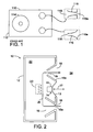
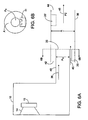
- a loudspeaker 110 includes an enclosure 112 and an acoustic driver 114.
- Ports 116 and 118 are flared.
- the upper port 118 is flared inwardly, that is, the interior end 118i has a larger cross-sectional area than the exterior end 118e.
- the lower port is flared outwardly, that is, the exterior end 116e has a larger cross-sectional area than the interior end 116i.
- Loudspeaker 10 includes an enclosure 12 and an acoustic driver 14 having a motor structure 15.
- In the enclosure are two ports, 16 and 18, positioned so that one port 16 is positioned lower in the enclosure 12 than the other port 18.
- Lower port 16 is flared inwardly, that is, interior end 16i has a larger cross -sectional area than the exterior end 16e.
- Upper port 18 is flared outwardly, that is, exterior end 18e has a larger cross-sectional area than the interior end 18i.
- the flares of port 16 and 18 are exaggerated. Actual dimensions of an exemplary port are presented below.
- the heat producing elements may include the motor structure 15 of the acoustic driver, or an optional heat producing device 20, such as a power supply or amplifier for loudspeaker 10 or for another loudspeaker, not shown, or both.
- Optional heat producing device 20 may be positioned lower than upper port 18 for better results. It may be advantageous to remove heat from motor structure 15, positioning it lower than upper port 18 for better results.
- a surface, such as cone 13, of acoustic driver 14 is driven by motor structure 15 so that the cone 13 vibrates in the direction indicated by arrow 17, radiating sound waves, in this case to the exterior 24 of the enclosure and the interior 22 of the enclosure.
- the motor structure 15 In driving the acoustic driver cone, the motor structure 15 generates heat that is introduced into enclosure interior 22. Sound waves radiated to the interior 22 of the enclosure result in sound waves radiated out through ports 16 and 18. In addition to the sound waves radiated out through the ports, there is a DC airflow as indicated by arrow 26.
- the DC airflow is described in more detail below.
- the DC airflow transfers heat away from motor structure 15 and optional heat producing element 20 through upper port 18 and out of the enclosure, thereby cooling the motor structure 15 and the optional heat producing element 20.
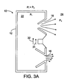
- the loudspeaker of FIG. 2 is shown to explain the DC airflow of FIG. 2 .
- the air pressure P i inside the enclosure alternately increases and decreases relative to the pressure P o of the air outside the enclosure.
- the pressure differential urges the air to flow from the interior 22 to the exterior 24 of the enclosure.
- the pressure differential urges the air to flow from the exterior 24 to the interior 22.
- a loudspeaker according to the invention is advantageous because there is a port-induced airflow that is in the same direction as the convective airflow, increasing the cooling efficiency.
- Empirical results indicate that thermal rise of a test setup using the configuration of FIG. 1 was reduced by about 21% as compared to the thermal rise with no signal to the acoustic driver 114. With the configuration of FIG. 2 , the thermal rise was reduced by about 75% as compared to the thermal rise with no signal to acoustic driver 14.
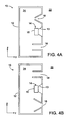
- FIGS. 4A - 4I several embodiments of the invention are shown.
- lower port 16 is a straight walled port, and the upper port is flared outwardly.
- upper port 18 is a straight walled port, and the lower port is flared inwardly.
- the embodiments of FIGS. 4A and 4B have an airflow similar to the airflow of the embodiment of FIGS. 2 and 3 , but the airflow is not as pronounced.
- FIG. 4C it is shown that the ports 16 and 18 can be on different sides of the enclosure 12; if the enclosure has curved sides, the ports 16 and 18 can be at any point on the curve.
- FIG. 4A lower port 16 is a straight walled port, and the upper port is flared outwardly.
- upper port 18 is a straight walled port, and the lower port is flared inwardly.
- the embodiments of FIGS. 4A and 4B have an airflow similar to the airflow of the embodiment of FIGS. 2 and 3 , but the airflow
- FIG. 4D is a front view, showing that acoustic driver 14 and the two ports 16 and 18 may be non-collinear.
- the position of the acoustic driver 14 and alternate locations shown in dashed lines, and the position of ports 16 and 18 and alternate locations shown in dashed lines show that the acoustic driver 14 need not be equidistant from ports 16 and 18 and that the acoustic driver need not be vertically centered between ports 16 and 18.
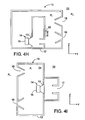
- the outwardly flaring upper port 18 is in the upper surface, facing upward, and the inwardly flaring lower port 16 is in the lower surface. If the lower port 16 is in the lower surface as in FIG.
- FIG. 4E the enclosure would typically have legs or some other spacing structure to space lower port 16 from surface 28 on which loudspeaker 10 rests.
- FIG. 4F shows that the port walls need not diverge linearly, and that the walls, in cross section, need not be straight lines.
- the embodiment of FIG. 4G shows that the divergence need not be monotonic, but can be flared both inwardly and outwardly, so long as the cross sectional area at the exterior end 18e of the upper port 18 is larger than the cross sectional area at the interior end 18i, or so long as the cross sectional area at the exterior end 16e of the lower port 16 is smaller than the cross sectional area at the interior end 16i, or both.
- Flaring a port in both directions may have acoustic advantages over straight walled ports or ports flared monotonically.
- the invention is incorporated in loudspeakers with more complex port and chamber structures, and with an acoustic driver that does not radiate directly to the exterior environment.
- Third port 117 of FIG. 5 is used for acoustic purposes.
- the operation of the embodiments of FIGS. 4H and 4I causes interior pressure P i to cycle above and below exterior pressure P o , resulting in a net DC airflow as in the other embodiments, even though acoustic driver 14 does not radiate sound waves directly to the exterior of the enclosure.
- FIGS. 4A - 4I can be combined.
- FIGS. 4A - 4I illustrate some of the many ways in which the invention may be implemented, not to show all the possible embodiments of the invention.
- there are an upper port and a lower port and either the upper port has a net outward flare, or the lower port has a net inward flare, or both.
- FIG. 5 there is shown a partially transparent view of a loudspeaker incorporating the invention.
- the cover 30 of the unit is removed to show internal detail of the loudspeaker.
- the embodiment of FIG. 5 is in the form of FIG. 4I .
- the reference numerals identify the elements of FIG. 5 that correspond to the like-numbered elements of FIG. 4I .
- Acoustic driver 14 (not shown in this view) is mounted in cavity 32. Openings 19 help reduce standing waves in the port tube as described below.
- the variations in the cross sectional areas of ports 16 and 18 are accomplished by varying the dimensions in the x, y, and z directions. Table 1 below shows exemplary dimensions of the two ports 16 and 18 of the loudspeaker of FIG. 5 .
- ported loudspeaker 10 has a port 40 that has a port exit 35 inside airflow passage 38.
- port 40 and airflow passage 38 are both pipe-like structures with one dimension long relative to the other dimensions, and with openings at the two lengthwise ends; port exit 35 has a cross-sectional area As smaller than the cross-sectional area A of the airflow passage 38; and port exit 35 is positioned in the airflow passage so that the longitudinal axes are parallel or coincident.
- Some considerations for the shape, dimensions, and placement of port 40, port exit 35, and airflow passage 38 are presented below.
- Positioned inside airflow passage 38 is heat producing device 20 or 20', shown at two locations. In an actual implementation, the heat producing device or devices can be placed at many other locations in airflow passage 38.
- acoustic driver 14 When acoustic driver 14 operates, it induces an airflow in and out of the port 40.
- the port and airflow pa ssage act as a jet pump, which causes airflow in the airflow passage 38 in the same direction as the airflow out of the port, in this example in airflow passage opening 42, through the airflow passage in direction 45 and out airflow passage opening 44.
- Jet pumps are described generally in documents such as at the internet location http://www.mas.ncl.ac.uk/ ⁇ sbrooks/book/nish.mit.edu/2006/Textbook/Nodes/cha p05/node16.html.
- the acoustic driver induced airflow is in direction 36, there is a jet pump effect that causes an airflow in airflow passage op ening 42 and out passage opening 44.
- the acoustic driver induced airflow is in the direction 37, there is little net airflow in airflow passage 38.
- the net result of the operation of the acoustic driver is a net DC airflow in direction 45.
- the net DC airflow can be used to transfer heat away from heat producing elements, such as devices 20 and 20', that are placed in the airflow path.
- the combined acoustic effect of port 40 and passage 38 is preferably in accordance with desired acoustic properties. It may be desirable to arrange port 40 to have the desired acoustic property and airflow passage 38 to have significantly less acoustic effect while maintaining the momentum of the airflow in desired direction 45 and to deter momentum in directions transverse to the desired direction. To this end port 40 may be relatively elongated and with a straight axis of elongation parallel to the desired momentum direction. It may be desirable to structure airflow passage 38 to increase the proportion of the airflow is laminar and decrease the proportion of the airflow that is turbulent while providing a desired amount of airflow.
- FIG. 7 there is shown a mechanical schematic drawing of an actual test implementation of the embodiment of FIGS. 6A and 6B , the elements numbered similarly to the corresponding elements of FIGS. 6A and 6B .
- the airflow passage 38 and the heat producing device were both parts of a unitary structure.
- a resistor was placed in thermal contact with at heat sink in a tubular form with appropriate dimensions so it could function as the airflow pass age 38.
- the temperature in the vicinity of the heatsink rose 47° C.
- the acoustic driver operating at 1/8 power, the temperature in the vicinity of the heatsink rose 39° C.
- the temperature in the vicinity of the heatsink rose 25° C.
- the thermal effect of the device at other points in the loudspeaker enclosure was measured. For example, at area 55, convection heating caused the temperature to rise 30.5° C with current flowing through the resistor and with acoustic driver 14 not operating.
- the temperature in the vicinity of the heatsink rose 30.5° C.
- the acoustic driver operating at 1/8 power radiating pink noise the temperature in the vicinity of the heatsink rose 30.5° C.
- the acoustic driver operating at 1/3 power radiating pink noise the temperature in the vicinity of the heatsink rose 21° C. This indicates that if the acoustic driver operates at high enough power, thereby moving more air than when it operates at lower power, the airflow resulting from a loudspeaker according to the invention transfers heat from areas near, but not directly in, the airflow.
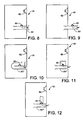
- FIG. 8 there is shown a diagrammatic representation of a loudspeaker enclosure 61 having a driver 62 and a port tube 63 formed with a vent 64 typically located at a point along the length of port tube 63 corresponding to the pressure maximum of the dominant standing wave established in port tube 63 when driver 62 is excited to reduce audible port noise.
- Acoustic damping material 90 for example, polyester or cloth, may be positioned in or near vent 64.
- This aspect reduces the objectionability of port noise caused by self resonances. For example, consider the case of increased noise at the frequency for which one-half wavelength is equal to the port length. In this example of self resonan ce, the standing waves in the port tube generate the highest pressure midway between the ends of port tube 63. By establishing a small resistive leak near this point with vent 64 in the side of the tube, the Q of the resonance is significantly diminished to significantly reduce the objectionability of port noise at this frequency.
- the acoustic damping material 90 may further reduce the Q of high frequency resonances.
- the leak can occur through vent 64 into the acoustic enclosure as shown in FIG. 8 .
- the leak can leak into the space outside enclosure 61 through vent 64' of port tube 63' as shown in FIG. 9 .
- the port tube 63" could leak through vent 64" to a different part of port tube 63" as shown in FIG. 10 .
- Port tube 63'" could leak through vent 64'" into a small volume 65 as shown in FIG. 11 .
- the port tube 63"" could leak through vent 64"" into a closed end resonant tube 65'.
- An advantage of the embodiments of FIGS. 11 and 12 is that the disclosed structure may have insignificant impact on the low frequency output.
- the acoustic damping material 90 may further reduce the Q of high frequency resonances.
- FIGS. 9-12 reduce the Q of the self resonance corresponding to the half-wave resonance of the port tube.
- the principles of the invention may be applied to reducing the Q at other frequencies corresponding to the wavelength resonance, 3/2 wavelength resonan ce and other resonances.
- each may have dedicated closed end resonant tubes. Still alternatively, they may allow leakage to the inside or outside of the enclosure.
- a multiplicity of vents may be used, including a slot, which can be considered as a series of contiguous vents.
- venting structures there are numerous combinations of venting structures, structures defining volumes for venting, including resonant closed end tubes.
- FIG. 13 there is shown a schematic representation of an embodiment for reducing Q of the half-wave resonance of a port tube 73 of length A1 in enclosure 71 having driver 72 using tube 75 with a closed end of length 0.3 A1 having its open end at vent 74.
- FIG. 14 shows the standing wave for the half-wave resonance along the length of tube 73, (in the absence of resonant tube 75), showing the pressure distribution 76 and volume velocity distribution 77. The pressure is at a maximum at point 74. Energy from the standing wave in the port tube 73 is removed from the port tube at maximum pressure point 74. The energy may be dissipated by damping material 90 in the resonant tube, significantly reducing the Q of the half-wave resonance.
- resonant tube 75 may be acoustic damping material.
- the acoustic damping material may fill only a small portion of the resonant tube 75 as indicated by acoustic damping material 90, or may substantially fill resonant tube as indicated in dotted line by acoustic damping material 90'.
- the acoustic damping material 90 or 90' reduces the Q of high frequency multiples of the half-wave resonant frequency.
- FIG. 15 there is shown a diagrammatic representation of a port tube 83 with a vent 84 six-tenths of the port tube length s from the left end and four-tenths of the port tube length from the right end terminated in a closed end resonant tube 85 of length 0.5 the length of port tube 83 and diameter d1 of 3" and another closed end tube 85' of length 0.25 that of port tube 83 and diameter d2 of 1.5".
- closed end resonant tube 85 and closed end resonant tube 85' may be acoustic damping material 90.
- the acoustic damping material may fill a portion of one or both of closed end resonant tubes 85, 85', or may substantially fill one or both of dose end resonant tubes 85, 85'.
Landscapes
- Physics & Mathematics (AREA)
- Engineering & Computer Science (AREA)
- Acoustics & Sound (AREA)
- Signal Processing (AREA)
- Details Of Audible-Bandwidth Transducers (AREA)
- Electrostatic, Electromagnetic, Magneto- Strictive, And Variable-Resistance Transducers (AREA)
Claims (11)
- Un appareil électroacoustique comprenant :une enceinte acoustique (12) comprenant un premier port acoustique et un second port acoustique (16, 18) ;un pilote acoustique (14) monté dans l'enceinte acoustique;une unité de chauffage (15, 20) placée dans l'enceinte (12) pour chauffer l'air ambiant et créant un courant d'air de convection ;le pilote acoustique (14), le premier port acoustique et le second port acoustique (16, 18) construits et disposés pour agir ensemble et fournir un courant d'air de refroidissement unidirectionnel qui se déplace essentiellement dans la même direction que le courant d'air de convection à travers l'unité de chauffage (15, 20), transférant ainsi la chaleur de l'unité de chauffage.
- Un appareil électroacoustique conformément à la Revendication 1, avec une enceinte acoustique (12) disposant d'un intérieur (22) et d'un extérieur (24) ;
la première (16i) et la deuxième (16e) extrémité du premier port acoustique ont une aire de section transversale et la première s'appuie sur l'intérieur tandis que la seconde s'appuie sur l'extérieur ; et
le second port acoustique (18) est situé au-dessus du premier port acoustique (16). - Un appareil électroacoustique conformément à la Revendication 2, le second port acoustique (18) disposant d'une première extrémité (18e) avec une aire de section transversale et une seconde extrémité (18i) avec une aire de section transversale, la première aire étant plus grande que la deuxième, et la deuxième s'appuyant sur l'intérieur (22) et la première sur l'extérieur (24).
- Un appareil électroacoustique conformément à la Revendication 2, l'enceinte acoustique (12) comprenant un point de montage pour l'unité de chauffage (15, 20) située en dessous du second port (18).
- Un appareil électroacoustique conformément à la Revendication 4, le point de montage étant construit et disposé pour le montage du pilote acoustique (14).
- Un appareil électroacoustique conformément à la Revendication 1, le premier port acoustique (18) possédant une extrémité intérieure (18i) et une extrémité extérieure (18), ces deux extrémités intérieure et extérieure possédant une aire de section transversale.
l'aire de section transversale de l'extrémité extérieure (18e) étant plus grande que celle de l'extrémité intérieure (18i)
le deuxième port acoustique (16) a une extrémité intérieure (16i) et une extrémité extérieure (16e), le premier port acoustique (18) étant situé au-dessus du second port acoustique. - Un appareil électroacoustique conformément à la Revendication 6, les extrémités intérieure (16i) et extérieure (16e) du port acoustique ayant chacune une aire de section transversale ;
l'aire de section transversale de l'extrémité intérieure du second port acoustique est plus grande que celle de l'extrémité extérieure du second port acoustique. - Un appareil électroacoustique conformément à la Revendication 6, le pilote acoustique (14) étant placé dans l'enceinte acoustique (12) plus haut que le second port acoustique et plus bas que le premier port acoustique.
- Un appareil électroacoustique conformément à la Revendication 1, l'enceinte acoustique (12) ayant une partie inférieure et une partie supérieure ;
le premier port acoustique (18) a une extrémité intérieure (18) et une extrémité extérieure (18e), ces deux extrémités présentant une aire de section transversale,
l'aire de section transversale de l'extrémité intérieure du premier port acoustique (18i) étant plus petite que celle de l'extrémité extérieure ;
le second port acoustique (16) a une extrémité intérieure (16i) et une extrémité extérieure (16e), ces deux extrémités présentant une aire de section transversale
l'aire de section transversale intérieure du second port acoustique étant plus grande que l'aire de section transversale extérieure. - Un appareil électroacoustique conformément à la Revendication 9, l'aire de section transversale extérieure du premier port acoustique étant placée plus près de la partie supérieure de l'enceinte acoustique que l'aire de section transversale intérieure du second port acoustique.
- Un appareil électroacoustique conformément à la Revendication 9 présentant une ouverture pour un transducteur électroacoustique placé au-dessus de l'extrémité intérieure du premier port acoustique et de l'extrémité intérieure du second port acoustique.
Applications Claiming Priority (2)
| Application Number | Priority Date | Filing Date | Title |
|---|---|---|---|
| US10/699,304 US7463744B2 (en) | 2003-10-31 | 2003-10-31 | Porting |
| US699304 | 2003-10-31 |
Publications (3)
| Publication Number | Publication Date |
|---|---|
| EP1528836A2 EP1528836A2 (fr) | 2005-05-04 |
| EP1528836A3 EP1528836A3 (fr) | 2006-06-07 |
| EP1528836B1 true EP1528836B1 (fr) | 2010-01-20 |
Family
ID=34423443
Family Applications (1)
| Application Number | Title | Priority Date | Filing Date |
|---|---|---|---|
| EP20040105332 Expired - Lifetime EP1528836B1 (fr) | 2003-10-31 | 2004-10-27 | Système d'admission et dissipation de chaleur dans des dispositifs acoustiques |
Country Status (5)
| Country | Link |
|---|---|
| US (4) | US7463744B2 (fr) |
| EP (1) | EP1528836B1 (fr) |
| JP (1) | JP4874536B2 (fr) |
| CN (1) | CN1617629B (fr) |
| DE (1) | DE602004025187D1 (fr) |
Families Citing this family (49)
| Publication number | Priority date | Publication date | Assignee | Title |
|---|---|---|---|---|
| US10842677B2 (en) * | 1996-03-11 | 2020-11-24 | Horst Burghardt Minkofski | Sound baffling device and material |
| US7463744B2 (en) * | 2003-10-31 | 2008-12-09 | Bose Corporation | Porting |
| US7565948B2 (en) * | 2004-03-19 | 2009-07-28 | Bose Corporation | Acoustic waveguiding |
| US7584820B2 (en) * | 2004-03-19 | 2009-09-08 | Bose Corporation | Acoustic radiating |
| US7689197B2 (en) * | 2006-12-22 | 2010-03-30 | Bose Corporation | Portable audio system with docking cradle |
| US8103035B2 (en) | 2006-12-22 | 2012-01-24 | Bose Corporation | Portable audio system having waveguide structure |
| JP4333778B2 (ja) | 2007-05-23 | 2009-09-16 | 船井電機株式会社 | スピーカを内蔵した機器、液晶テレビジョン受像機 |
| JP5128919B2 (ja) * | 2007-11-30 | 2013-01-23 | 船井電機株式会社 | マイクロフォンユニット及び音声入力装置 |
| JP2009290346A (ja) * | 2008-05-27 | 2009-12-10 | Panasonic Electric Works Co Ltd | パネルスピーカ装置 |
| DE102009046889A1 (de) * | 2009-11-19 | 2011-07-21 | K+H Vertriebs- und Entwicklungsgesellschaft mbH, 30900 | Lautsprechereinheit |
| FR2955731B1 (fr) * | 2010-01-22 | 2012-08-24 | Canon Kk | Enceinte acoustique comprenant au moins une membrane d'attenuation acoustique |
| CN102143418B (zh) * | 2011-02-18 | 2014-11-05 | 徐新国 | 空气对流式倒相音箱 |
| US8744108B2 (en) | 2011-07-12 | 2014-06-03 | Strata Audio LLC | Balanced momentum inertial duct |
| US8561756B2 (en) | 2012-02-17 | 2013-10-22 | Bose Corporation | Acoustic ports aligned to create free convective airflow |
| US8798308B2 (en) | 2012-02-21 | 2014-08-05 | Bose Corporation | Convective airflow using a passive radiator |
| US9173018B2 (en) | 2012-06-27 | 2015-10-27 | Bose Corporation | Acoustic filter |
| US9215520B2 (en) | 2012-08-15 | 2015-12-15 | General Electric Company | Multi-function synthetic jet and method of manufacturing same |
| BR112015024214A2 (pt) | 2013-03-22 | 2017-09-26 | Campobello Ltd | duto supressor de ruído, módulo supressor de ruído, dispositivo acústico para uso com um elemento de alto-falante móvel, controlador, e, alto-falante. |
| CN103220608B (zh) * | 2013-04-16 | 2016-08-24 | 歌尔声学股份有限公司 | 扬声器模组 |
| US9301043B2 (en) | 2013-05-01 | 2016-03-29 | Harman International Industries, Inc. | Sealed speaker system having a pressure vent |
| TWI531248B (zh) * | 2013-08-23 | 2016-04-21 | 宏碁股份有限公司 | 音箱結構 |
| US20160037253A1 (en) * | 2014-07-30 | 2016-02-04 | Goal Zero Llc | Portable speaker system |
| US9860660B1 (en) | 2014-09-30 | 2018-01-02 | Apple Inc. | Electronic device with speaker cavity cooling |
| US10045461B1 (en) * | 2014-09-30 | 2018-08-07 | Apple Inc. | Electronic device with diaphragm cooling |
| US10631093B2 (en) * | 2015-01-26 | 2020-04-21 | Harman International Industries, Incorporated | Vented loudspeaker system with duct for cooling of internal components |
| US9571935B2 (en) | 2015-01-26 | 2017-02-14 | Harman International Industries, Inc. | Loudspeaker with ducts for transducer voice coil cooling |
| US10701491B2 (en) * | 2015-12-17 | 2020-06-30 | Eric Jay Alexander | Fluid diode loudspeaker |
| US9906855B2 (en) * | 2015-12-28 | 2018-02-27 | Bose Corporation | Reducing ported transducer array enclosure noise |
| US9913024B2 (en) * | 2015-12-28 | 2018-03-06 | Bose Corporation | Acoustic resistive elements for ported transducer enclosure |
| US10123111B2 (en) * | 2016-06-03 | 2018-11-06 | Fulcrum Acoustic, LLC | Passive cardioid speaker |
| US10290302B2 (en) * | 2016-12-30 | 2019-05-14 | Google Llc | Compact home assistant with combined acoustic waveguide and heat sink |
| CN106792335B (zh) * | 2017-01-05 | 2019-09-06 | 联想(北京)有限公司 | 一种电子设备 |
| US10142726B2 (en) * | 2017-01-31 | 2018-11-27 | Sonos, Inc. | Noise reduction for high-airflow audio transducers |
| JP6641644B2 (ja) * | 2017-02-15 | 2020-02-05 | カシオ計算機株式会社 | スピーカボックスおよび投影装置 |
| US10438868B2 (en) * | 2017-02-20 | 2019-10-08 | Microjet Technology Co., Ltd. | Air-cooling heat dissipation device |
| US11148048B2 (en) * | 2017-03-07 | 2021-10-19 | Sony Corporation | Content presentation system, content presentation device, and wind presenting device |
| EP3383059A1 (fr) * | 2017-03-27 | 2018-10-03 | Vestel Elektronik Sanayi ve Ticaret A.S. | Dispositif électronique grand public et procédé de fonctionnement d'un dispositif électronique grand public |
| US10306356B2 (en) | 2017-03-31 | 2019-05-28 | Bose Corporation | Acoustic deflector as heat sink |
| USD872054S1 (en) | 2017-08-04 | 2020-01-07 | Bose Corporation | Speaker |
| JP6277314B1 (ja) * | 2017-08-07 | 2018-02-07 | 勝巳 瀬戸 | スピーカー装置 |
| WO2019040108A2 (fr) * | 2017-08-21 | 2019-02-28 | Out of the Box Audio, LLC | Procédés et appareil permettant d'améliorer le son à l'intérieur d'une couche limite acoustique |
| CN111133771B (zh) * | 2017-09-27 | 2022-09-13 | 哈曼贝克自动系统股份有限公司 | 扬声器装置 |
| US10425739B2 (en) * | 2017-10-03 | 2019-09-24 | Bose Corporation | Acoustic deflector with convective cooling |
| US20190253790A1 (en) | 2018-02-15 | 2019-08-15 | Alexander B Ralph | Ported tweeter |
| DE102019108423B4 (de) * | 2019-04-01 | 2021-08-05 | Svetlomir Aleksandrov | Lautsprecherbox und Lautsprecher |
| US11540417B2 (en) * | 2019-08-14 | 2022-12-27 | AAC Technologies Pte. Ltd. | Sounding device and mobile terminal |
| US11310587B2 (en) | 2019-10-08 | 2022-04-19 | Bose Corporation | Horn loudspeakers |
| JP6857271B1 (ja) * | 2019-10-14 | 2021-04-14 | シャープ株式会社 | スピーカ装置及び表示装置 |
| US11917361B2 (en) * | 2020-08-12 | 2024-02-27 | Michael Levy | Loudspeaker |
Family Cites Families (66)
| Publication number | Priority date | Publication date | Assignee | Title |
|---|---|---|---|---|
| US3393766A (en) | 1966-05-18 | 1968-07-23 | American District Telegraph Co | Speaker system |
| US3517390A (en) * | 1968-02-29 | 1970-06-23 | Layne Whitehead | High power acoustic radiator |
| GB1487847A (en) | 1974-09-25 | 1977-10-05 | Ard Anstalt | Microphone units |
| JPS5333613A (en) | 1976-09-09 | 1978-03-29 | Matsushita Electric Ind Co Ltd | Microphone and its manufacture |
| US4146744A (en) | 1976-09-02 | 1979-03-27 | Bose Corporation | Low q multiple in phase high compliance driver ported loudspeaker enclosure |
| JPS6013167Y2 (ja) | 1977-09-07 | 1985-04-26 | 株式会社日立製作所 | マグネトロン |
| JPS55152766A (en) * | 1979-05-17 | 1980-11-28 | Canon Inc | Recording liquid |
| US4307825A (en) | 1979-09-24 | 1981-12-29 | Pattermann Norbert C | Bricklayers trowel holster |
| DE3025569A1 (de) | 1980-07-05 | 1982-02-04 | Klaus 4400 Münster Burhans | Zusatzvorrichtung fuer eine wasserstrahlpumpe |
| JPS57131069A (en) * | 1981-02-06 | 1982-08-13 | Matsushita Electric Works Ltd | Circuit for detecting voltage variation |
| US4906864A (en) | 1984-10-01 | 1990-03-06 | United Technologies Corporation | Linear slope peak detector |
| JPS61219289A (ja) | 1985-03-25 | 1986-09-29 | Matsushita Electric Ind Co Ltd | アンプ付スピ−カシステム |
| JPS62143841A (ja) | 1985-12-16 | 1987-06-27 | Nippon Sheet Glass Co Ltd | カルコゲナイドガラス |
| JPS6374297A (ja) | 1986-09-17 | 1988-04-04 | Mitsubishi Electric Corp | スピ−カ−システム |
| US4802227A (en) | 1987-04-03 | 1989-01-31 | American Telephone And Telegraph Company | Noise reduction processing arrangement for microphone arrays |
| US4811403A (en) * | 1987-06-10 | 1989-03-07 | U.S. Sound, Inc. | Ultralight loudspeaker enclosures |
| JPH01149192A (ja) * | 1987-12-07 | 1989-06-12 | Toshiba Corp | ショーケース兼用形自動販売機 |
| US5012890A (en) * | 1988-03-23 | 1991-05-07 | Yamaha Corporation | Acoustic apparatus |
| JPH01241297A (ja) | 1988-03-23 | 1989-09-26 | Yamaha Corp | 音響装置 |
| JPH01241296A (ja) | 1988-03-23 | 1989-09-26 | Yamaha Corp | 音響装置 |
| DE68919495T2 (de) * | 1988-03-25 | 1995-07-20 | Yamaha Corp | Akustischer Apparat. |
| EP0336303A3 (fr) | 1988-04-04 | 1991-05-15 | Yamaha Corporation | Appareil acoustique |
| US4875546A (en) * | 1988-06-02 | 1989-10-24 | Teledyne Industries, Inc. | Loudspeaker with acoustic band-pass filter |
| US5109422A (en) * | 1988-09-28 | 1992-04-28 | Yamaha Corporation | Acoustic apparatus |
| US4903300A (en) * | 1989-01-05 | 1990-02-20 | Polk Investment Corporation | Compact and efficient sub-woofer system and method for installation in structural partitions |
| US5150471A (en) * | 1989-04-20 | 1992-09-22 | Ncr Corporation | Method and apparatus for offset register address accessing |
| NL8902831A (nl) * | 1989-11-16 | 1991-06-17 | Philips Nv | Luidsprekersysteem bevattende een helmholtz resonator gekoppeld met een akoestische buis. |
| JP3186049B2 (ja) * | 1990-03-13 | 2001-07-11 | 松下電器産業株式会社 | スピーカ装置 |
| US5275693A (en) | 1990-03-30 | 1994-01-04 | Yamato Kako Kabushiki Kaisha | Film forming process |
| US5005744A (en) | 1990-08-03 | 1991-04-09 | Gleason Dana W | Adjustable backpack |
| US5150417A (en) | 1991-02-25 | 1992-09-22 | Socon Ab | Bass reflex type speaker system |
| US5357586A (en) * | 1991-05-16 | 1994-10-18 | The Nordschow/Wright Loudspeaker Company | Flow-through air-cooled loudspeaker system |
| EP0529169A1 (fr) * | 1991-08-29 | 1993-03-03 | International Business Machines Corporation | Dispositif de connexion d'un équipement de communication à un réseau de communication numérique avec au moins deux canaux de communication numériques |
| JP3279612B2 (ja) | 1991-12-06 | 2002-04-30 | ソニー株式会社 | 雑音低減装置 |
| US5740259A (en) | 1992-06-04 | 1998-04-14 | Bose Corporation | Pressure wave transducing |
| DE69323258T2 (de) * | 1992-09-23 | 1999-08-05 | Koninklijke Philips Electronics N.V., Eindhoven | Lautsprechersystem mit mehreren Rohren |
| US5373564A (en) | 1992-10-02 | 1994-12-13 | Spear; Robert J. | Transmission line for planar waves |
| JPH06167982A (ja) | 1992-11-30 | 1994-06-14 | Mitsubishi Electric Corp | 多孔質吸音材を用いた吸音ダクト |
| JPH06245286A (ja) * | 1993-02-19 | 1994-09-02 | Sony Corp | スピーカ |
| US6278789B1 (en) | 1993-05-06 | 2001-08-21 | Bose Corporation | Frequency selective acoustic waveguide damping |
| US5589799A (en) | 1994-09-29 | 1996-12-31 | Tibbetts Industries, Inc. | Low noise amplifier for microphone |
| JPH08140177A (ja) | 1994-11-14 | 1996-05-31 | Matsushita Electric Ind Co Ltd | スピーカシステム |
| US6223853B1 (en) * | 1994-12-23 | 2001-05-01 | Graeme John Huon | Loudspeaker system incorporating acoustic waveguide filters and method of construction |
| US5533132A (en) * | 1995-01-23 | 1996-07-02 | Jbl Incorporated | Loudspeaker thermal management structure |
| IL117666A0 (en) | 1995-03-31 | 1996-07-23 | Bsg Lab Inc | Low frequency audio coupler and method of coupling |
| US5673330A (en) | 1995-11-08 | 1997-09-30 | Chang; Ching-Lu | Microphone transducer with noise reducing member |
| US6009184A (en) | 1996-10-08 | 1999-12-28 | Umevoice, Inc. | Noise control device for a boom mounted noise-canceling microphone |
| JPH10148181A (ja) * | 1996-11-19 | 1998-06-02 | Shinten Sangyo Kk | エアポンプ |
| US5792999A (en) * | 1997-01-23 | 1998-08-11 | Bose Corporation | Noise attenuating in ported enclosure |
| US6275597B1 (en) * | 1998-05-27 | 2001-08-14 | U.S. Philips Corporation | Loudspeaker system having a bass-reflex port |
| US6549637B1 (en) * | 1998-09-24 | 2003-04-15 | Peavey Electronics Corp. | Loudspeaker with differential flow vent means |
| US6169811B1 (en) * | 1999-03-02 | 2001-01-02 | American Technology Corporation | Bandpass loudspeaker system |
| US7103193B2 (en) * | 2000-09-15 | 2006-09-05 | American Technology Corporation | Bandpass woofer enclosure with multiple acoustic fibers |
| JP2001346283A (ja) | 2000-06-01 | 2001-12-14 | Matsushita Electric Ind Co Ltd | スピーカシステム |
| US6549037B1 (en) * | 2000-06-26 | 2003-04-15 | Intel Corporation | Apparatus and circuit having reduced leakage current and method therefor |
| CN1480000A (zh) | 2000-10-12 | 2004-03-03 | ���ŷ� | 基于数字光线处理的3d投影系统与方法 |
| US7426280B2 (en) * | 2001-01-02 | 2008-09-16 | Bose Corporation | Electroacoustic waveguide transducing |
| TW580826B (en) | 2001-01-12 | 2004-03-21 | Vrex Inc | Method and apparatus for stereoscopic display using digital light processing |
| US7711134B2 (en) * | 2001-06-25 | 2010-05-04 | Harman International Industries, Incorporated | Speaker port system for reducing boundary layer separation |
| JP4086622B2 (ja) * | 2002-03-11 | 2008-05-14 | ローランド株式会社 | スピーカ装置 |
| US7123736B2 (en) * | 2002-09-27 | 2006-10-17 | Sony Ericsson Mobile Communications Ab | Double-resonator micro-speaker assemblies and methods for tuning the same |
| JP2004285895A (ja) | 2003-03-20 | 2004-10-14 | Toyoda Gosei Co Ltd | 吸気装置 |
| US7463744B2 (en) * | 2003-10-31 | 2008-12-09 | Bose Corporation | Porting |
| US7584820B2 (en) | 2004-03-19 | 2009-09-08 | Bose Corporation | Acoustic radiating |
| JP2008131199A (ja) | 2006-11-17 | 2008-06-05 | Pioneer Electronic Corp | スピーカ装置 |
| US8351630B2 (en) | 2008-05-02 | 2013-01-08 | Bose Corporation | Passive directional acoustical radiating |
-
2003
- 2003-10-31 US US10/699,304 patent/US7463744B2/en not_active Expired - Lifetime
-
2004
- 2004-10-27 DE DE200460025187 patent/DE602004025187D1/de not_active Expired - Lifetime
- 2004-10-27 EP EP20040105332 patent/EP1528836B1/fr not_active Expired - Lifetime
- 2004-10-29 CN CN200410089636.4A patent/CN1617629B/zh not_active Expired - Fee Related
- 2004-10-29 JP JP2004315046A patent/JP4874536B2/ja not_active Expired - Fee Related
-
2008
- 2008-10-09 US US12/248,326 patent/US20090041282A1/en not_active Abandoned
-
2009
- 2009-04-01 US US12/416,516 patent/US8107662B2/en not_active Expired - Fee Related
-
2011
- 2011-12-22 US US13/335,533 patent/US8831263B2/en not_active Expired - Lifetime
Also Published As
| Publication number | Publication date |
|---|---|
| US8107662B2 (en) | 2012-01-31 |
| DE602004025187D1 (de) | 2010-03-11 |
| US7463744B2 (en) | 2008-12-09 |
| CN1617629B (zh) | 2015-09-30 |
| US20120328141A1 (en) | 2012-12-27 |
| US20050094837A1 (en) | 2005-05-05 |
| HK1078231A1 (en) | 2006-03-03 |
| EP1528836A3 (fr) | 2006-06-07 |
| US20090041282A1 (en) | 2009-02-12 |
| US20090245563A1 (en) | 2009-10-01 |
| JP2005176316A (ja) | 2005-06-30 |
| US8831263B2 (en) | 2014-09-09 |
| CN1617629A (zh) | 2005-05-18 |
| JP4874536B2 (ja) | 2012-02-15 |
| EP1528836A2 (fr) | 2005-05-04 |
Similar Documents
| Publication | Publication Date | Title |
|---|---|---|
| EP1528836B1 (fr) | Système d'admission et dissipation de chaleur dans des dispositifs acoustiques | |
| US7793709B2 (en) | Jet generating device and electronic apparatus | |
| EP0873595B1 (fr) | Structure de regulation thermique pour haut-parleur | |
| CN104205870B (zh) | 用于重现声信号的装置及冷却音箱的方法 | |
| US11381919B2 (en) | Speaker box and speaker | |
| US5097513A (en) | Speaker system enclosure integrated with amplifier circuit board | |
| EP3692727B1 (fr) | Déflecteur acoustique avec refroidissement par convection | |
| CN101542724A (zh) | 脉动冷却系统 | |
| WO1992021217A1 (fr) | Systeme de haut-parleur refroidi par air de circulation | |
| CN1671248A (zh) | 声音辐射 | |
| US20070104347A1 (en) | Angled thermal chimney in audio speaker cabinet | |
| KR100453900B1 (ko) | 플라즈마 디스플레이 패널을 채용한 화상 표시장치 | |
| US7349207B2 (en) | Heat dissipating audio systems and methods thereof | |
| CN101889145B (zh) | 低噪声冷却设备 | |
| US20200112792A1 (en) | Speaker Integrated Electronic Device with Speaker Driven Passive Cooling | |
| HK1078231B (en) | Porting | |
| US20250274715A1 (en) | Speaker apparatus | |
| CN219302859U (zh) | 一种利用音箱辅助散热的lcd投影机 | |
| WO2017053714A1 (fr) | Dispositif électronique de sortie audio compact à dissipation de chaleur | |
| CN223666423U (zh) | 音箱 | |
| CN214592556U (zh) | 一种静音散热器及电子设备 | |
| CN111492665A (zh) | 低音反射型扬声器封壳 | |
| JP3816016B2 (ja) | バスレフ型スピーカー装置 | |
| JP2001346283A (ja) | スピーカシステム | |
| JPH07154885A (ja) | スピーカ組立体 |
Legal Events
| Date | Code | Title | Description |
|---|---|---|---|
| PUAI | Public reference made under article 153(3) epc to a published international application that has entered the european phase |
Free format text: ORIGINAL CODE: 0009012 |
|
| AK | Designated contracting states |
Kind code of ref document: A2 Designated state(s): AT BE BG CH CY CZ DE DK EE ES FI FR GB GR HU IE IT LI LU MC NL PL PT RO SE SI SK TR |
|
| AX | Request for extension of the european patent |
Extension state: AL HR LT LV MK |
|
| PUAL | Search report despatched |
Free format text: ORIGINAL CODE: 0009013 |
|
| AK | Designated contracting states |
Kind code of ref document: A3 Designated state(s): AT BE BG CH CY CZ DE DK EE ES FI FR GB GR HU IE IT LI LU MC NL PL PT RO SE SI SK TR |
|
| AX | Request for extension of the european patent |
Extension state: AL HR LT LV MK |
|
| 17P | Request for examination filed |
Effective date: 20061201 |
|
| AKX | Designation fees paid |
Designated state(s): DE GB |
|
| 17Q | First examination report despatched |
Effective date: 20070618 |
|
| GRAP | Despatch of communication of intention to grant a patent |
Free format text: ORIGINAL CODE: EPIDOSNIGR1 |
|
| GRAS | Grant fee paid |
Free format text: ORIGINAL CODE: EPIDOSNIGR3 |
|
| GRAA | (expected) grant |
Free format text: ORIGINAL CODE: 0009210 |
|
| AK | Designated contracting states |
Kind code of ref document: B1 Designated state(s): DE GB |
|
| REG | Reference to a national code |
Ref country code: GB Ref legal event code: FG4D |
|
| REF | Corresponds to: |
Ref document number: 602004025187 Country of ref document: DE Date of ref document: 20100311 Kind code of ref document: P |
|
| PLBE | No opposition filed within time limit |
Free format text: ORIGINAL CODE: 0009261 |
|
| STAA | Information on the status of an ep patent application or granted ep patent |
Free format text: STATUS: NO OPPOSITION FILED WITHIN TIME LIMIT |
|
| 26N | No opposition filed |
Effective date: 20101021 |
|
| PGFP | Annual fee paid to national office [announced via postgrant information from national office to epo] |
Ref country code: GB Payment date: 20191028 Year of fee payment: 16 |
|
| PGFP | Annual fee paid to national office [announced via postgrant information from national office to epo] |
Ref country code: DE Payment date: 20201028 Year of fee payment: 17 |
|
| GBPC | Gb: european patent ceased through non-payment of renewal fee |
Effective date: 20201027 |
|
| PG25 | Lapsed in a contracting state [announced via postgrant information from national office to epo] |
Ref country code: GB Free format text: LAPSE BECAUSE OF NON-PAYMENT OF DUE FEES Effective date: 20201027 |
|
| REG | Reference to a national code |
Ref country code: DE Ref legal event code: R119 Ref document number: 602004025187 Country of ref document: DE |
|
| PG25 | Lapsed in a contracting state [announced via postgrant information from national office to epo] |
Ref country code: DE Free format text: LAPSE BECAUSE OF NON-PAYMENT OF DUE FEES Effective date: 20220503 |