EP1528618B1 - Verfahren zur Messung der relativen Dielektrizitätskonstante einer dielektrischen Pulversubstanz, dazu verwendeter Hohlraumresonator und Anwendungsvorrichtung - Google Patents
Verfahren zur Messung der relativen Dielektrizitätskonstante einer dielektrischen Pulversubstanz, dazu verwendeter Hohlraumresonator und Anwendungsvorrichtung Download PDFInfo
- Publication number
- EP1528618B1 EP1528618B1 EP04023517A EP04023517A EP1528618B1 EP 1528618 B1 EP1528618 B1 EP 1528618B1 EP 04023517 A EP04023517 A EP 04023517A EP 04023517 A EP04023517 A EP 04023517A EP 1528618 B1 EP1528618 B1 EP 1528618B1
- Authority
- EP
- European Patent Office
- Prior art keywords
- relative dielectric
- dielectric constant
- powders
- mixed substance
- substance
- Prior art date
- Legal status (The legal status is an assumption and is not a legal conclusion. Google has not performed a legal analysis and makes no representation as to the accuracy of the status listed.)
- Expired - Lifetime
Links
- 239000000126 substance Substances 0.000 title claims description 273
- 239000000843 powder Substances 0.000 title claims description 204
- 238000000034 method Methods 0.000 title claims description 56
- 239000007788 liquid Substances 0.000 claims description 163
- 239000000203 mixture Substances 0.000 claims description 29
- 230000004044 response Effects 0.000 claims description 14
- 238000007789 sealing Methods 0.000 claims description 14
- 239000002270 dispersing agent Substances 0.000 claims description 10
- 238000002156 mixing Methods 0.000 claims description 3
- 239000000523 sample Substances 0.000 description 124
- XLYOFNOQVPJJNP-UHFFFAOYSA-N water Substances O XLYOFNOQVPJJNP-UHFFFAOYSA-N 0.000 description 18
- 239000000919 ceramic Substances 0.000 description 13
- 238000005342 ion exchange Methods 0.000 description 11
- LFQSCWFLJHTTHZ-UHFFFAOYSA-N Ethanol Chemical compound CCO LFQSCWFLJHTTHZ-UHFFFAOYSA-N 0.000 description 9
- 230000005684 electric field Effects 0.000 description 8
- 238000005259 measurement Methods 0.000 description 7
- 238000004088 simulation Methods 0.000 description 7
- OKKJLVBELUTLKV-UHFFFAOYSA-N Methanol Chemical compound OC OKKJLVBELUTLKV-UHFFFAOYSA-N 0.000 description 6
- 230000006872 improvement Effects 0.000 description 6
- 238000013213 extrapolation Methods 0.000 description 4
- 229910003080 TiO4 Inorganic materials 0.000 description 3
- PNEYBMLMFCGWSK-UHFFFAOYSA-N aluminium oxide Inorganic materials [O-2].[O-2].[O-2].[Al+3].[Al+3] PNEYBMLMFCGWSK-UHFFFAOYSA-N 0.000 description 3
- 229910002113 barium titanate Inorganic materials 0.000 description 3
- 229910052593 corundum Inorganic materials 0.000 description 3
- 238000003780 insertion Methods 0.000 description 3
- 230000037431 insertion Effects 0.000 description 3
- 238000003756 stirring Methods 0.000 description 3
- BFKJFAAPBSQJPD-UHFFFAOYSA-N tetrafluoroethene Chemical group FC(F)=C(F)F BFKJFAAPBSQJPD-UHFFFAOYSA-N 0.000 description 3
- 229910001845 yogo sapphire Inorganic materials 0.000 description 3
- 238000004364 calculation method Methods 0.000 description 2
- 238000010586 diagram Methods 0.000 description 2
- 239000006185 dispersion Substances 0.000 description 2
- 230000005540 biological transmission Effects 0.000 description 1
- 230000015556 catabolic process Effects 0.000 description 1
- 230000008859 change Effects 0.000 description 1
- 239000002131 composite material Substances 0.000 description 1
- 238000006731 degradation reaction Methods 0.000 description 1
- 230000001419 dependent effect Effects 0.000 description 1
- 230000006866 deterioration Effects 0.000 description 1
- 239000000463 material Substances 0.000 description 1
- 230000007246 mechanism Effects 0.000 description 1
- 239000011347 resin Substances 0.000 description 1
- 229920005989 resin Polymers 0.000 description 1
- 238000005245 sintering Methods 0.000 description 1
Images









Classifications
-
- G—PHYSICS
- G01—MEASURING; TESTING
- G01N—INVESTIGATING OR ANALYSING MATERIALS BY DETERMINING THEIR CHEMICAL OR PHYSICAL PROPERTIES
- G01N22/00—Investigating or analysing materials by the use of microwaves or radio waves, i.e. electromagnetic waves with a wavelength of one millimetre or more
-
- G—PHYSICS
- G01—MEASURING; TESTING
- G01R—MEASURING ELECTRIC VARIABLES; MEASURING MAGNETIC VARIABLES
- G01R27/00—Arrangements for measuring resistance, reactance, impedance, or electric characteristics derived therefrom
- G01R27/02—Measuring real or complex resistance, reactance, impedance, or other two-pole characteristics derived therefrom, e.g. time constant
- G01R27/26—Measuring inductance or capacitance; Measuring quality factor, e.g. by using the resonance method; Measuring loss factor; Measuring dielectric constants ; Measuring impedance or related variables
-
- G—PHYSICS
- G01—MEASURING; TESTING
- G01R—MEASURING ELECTRIC VARIABLES; MEASURING MAGNETIC VARIABLES
- G01R27/00—Arrangements for measuring resistance, reactance, impedance, or electric characteristics derived therefrom
- G01R27/02—Measuring real or complex resistance, reactance, impedance, or other two-pole characteristics derived therefrom, e.g. time constant
- G01R27/04—Measuring real or complex resistance, reactance, impedance, or other two-pole characteristics derived therefrom, e.g. time constant in circuits having distributed constants, e.g. having very long conductors or involving high frequencies
- G01R27/06—Measuring reflection coefficients; Measuring standing-wave ratio
-
- H—ELECTRICITY
- H01—ELECTRIC ELEMENTS
- H01P—WAVEGUIDES; RESONATORS, LINES, OR OTHER DEVICES OF THE WAVEGUIDE TYPE
- H01P7/00—Resonators of the waveguide type
- H01P7/06—Cavity resonators
Definitions
- the present invention relates to a method of measuring a relative dielectric constant of a dielectric substance of powders and, more particularly, a method of measuring a relative dielectric constant of powders capable of measuring a relative dielectric constant of a dielectric substance of powders with high precision even in a high-frequency band in excess of several GHz.
- the ceramics dielectric substances are used in the form of sintered products that are obtained by sintering the powder dielectric substance.
- the composite dielectric substance in which the powder dielectric substance and the resin, or the like are mixed in various ratios is employed as the circuit parts.
- powders whose relative dielectric constant is to be measured are sealed in the vessel in which a pair of electrodes are arranged to oppose to each other at a predetermined interval, and then the relative dielectric constant of the powders is measured. Then, the relative dielectric constant of a mixed substance consisting of the powders and a liquid is measured by applying a voltage between a pair of electrodes, and then the relative dielectric constant of the powders is calculated based on the measured relative dielectric constant of the mixed substance.
- a method of measuring a relative dielectric constant of powders comprising the steps of calculating a relative dielectric constant of a mixed substance consisting of powders and a liquid medium, and then calculating the relative dielectric constant of the mixed substance or a relative dielectric constant of the liquid medium as the relative dielectric constant of the powders when the relative dielectric constant of the mixed substance becomes equal to the relative dielectric constant of the liquid medium is also disclosed.
- a method of measuring a relative dielectric constant of powders comprising the steps of sealing a mixed substance consisting of the powders and a liquid medium in a resonator, then inputting an electromagnetic wave into the resonator, then calculating a relative dielectric constant of the mixed substance based on a response of the electromagnetic wave, and then calculating a relative dielectric constant of the powders from the relative dielectric constant of the mixed substance and a relative dielectric constant of the liquid medium is also disclosed.
- a method of measuring a relative dielectric constant of powders comprising the steps of inputting an electromagnetic wave into a vessel in which a mixed substance consisting of the powders and a liquid medium is filled, then calculating a relative dielectric constant of the mixed substance based on a response of the electromagnetic wave, and then calculating a relative dielectric constant of the powders from the relative dielectric constant of the mixed substance and a relative dielectric constant of the liquid medium is also disclosed.
- Calculation of the relative dielectric constant of powders can be executed by calculating the relative dielectric constant of the mixed substance or the relative dielectric constant of the liquid medium as the relative dielectric constant of the powders when the relative dielectric constant of the mixed substance becomes equal to the relative dielectric constant of the liquid medium.
- a procedure of detecting a point of time when the relative dielectric constant of the mixed substance becomes equal to the relative dielectric constant of the liquid medium is executed by measuring the relative dielectric constant of the mixed substance while changing gradually the relative dielectric constant of the liquid medium.
- the liquid medium can contain a liquid, or a liquid and a powder dielectric substance, or a liquid, a powder dielectric substance, and a dispersing agent.
- a method of measuring a relative dielectric constant of powders which comprises the steps of sealing a mixed substance consisting of powders and a liquid medium in a resonator, then inputting an electromagnetic wave into the resonator, then calculating a relative dielectric constant of the mixed substance based on a response of the electromagnetic wave, and then calculating a relative dielectric constant of the powders from the calculated relative dielectric constant of the mixed substance and a volume ratio of the powders in the mixed substance is also disclosed.
- a method of measuring a relative dielectric constant of powders which comprises the steps of inputting an electromagnetic wave into a vessel in which a mixed substance consisting of powders and a liquid medium is filled, then calculating a relative dielectric constant of the mixed substance based on a response of the electromagnetic wave, and then calculating a relative dielectric constant of the powders from the calculated relative dielectric constant of the mixed substance and a volume ratio of the powders in the mixed substance is also disclosed.
- the relative dielectric constant of the liquid medium can be 0.5 times or more the relative dielectric constant of a powder composition.
- the relative dielectric constant of the liquid medium can be 0.5 times to 2.0 times the relative dielectric constant of a powder composition.
- the liquid medium can contain a liquid, or a liquid and a powder dielectric substance, or a liquid, a powder dielectric substance, and a dispersing agent. Calculation of the relative dielectric constant of powders can be executed by using the logarithmic mixture rule or the Lichtenecker-Rother's Formula.
- a cavity resonator which is used in a method of measuring a relative dielectric constant of powders that comprises the steps of sealing a mixed substance consisting of powders and a liquid medium in a resonator, then inputting an electromagnetic wave into the resonator, then calculating a relative dielectric constant of the mixed substance based on a response of the electromagnetic wave, and then calculating a relative dielectric constant of the powders from the relative dielectric constant of the mixed substance and a relative dielectric constant of the liquid medium, and in which at least one opening portion into which a measured dielectric substance is inserted is formed in the cavity resonator and also a supporter is formed on an outside of the opening portion, wherein a relationship h/d between a length d of the opening portion and a length h of the supporter is set to 0.5 or more.
- the cut-off structure can be obtained by preventing the leakage of the electromagnetic wave from the opening portion of the resonator.
- a cavity resonator which is used in a method of measuring a relative dielectric constant of powders comprising the steps of sealing a mixed substance consisting of powders and a liquid medium in a resonator, then inputting an electromagnetic wave into the resonator, then calculating a relative dielectric constant of the mixed substance based on a response of the electromagnetic wave, and then calculating a relative dielectric constant of the powders from the calculated relative dielectric constant of the mixed substance and a volume ratio of the powders in the mixed substance, and in which at least one opening portion into which a measured dielectric substance is inserted is formed in the cavity resonator and also a supporter is formed on an outside of the opening portion, wherein a relationship h/d between a length d of the opening portion and a length h of the supporter is set to 0.5 or more.
- the cut-off structure can be obtained by preventing the leakage of the electromagnetic wave from the opening portion of the resonator, and the resonant frequency and the unloaded Q value of
- the dielectric substance measuring system for inserting the rod-like-shaped dielectric substance into the cavity resonator, then measuring the resonant frequency and the unloaded Q value of the cavity resonator, and then measuring the relative dielectric constant and the dielectric loss tangent of the inserted rod-like dielectric substance based on the measured results is implemented.
- the resonator or the filter that can attain the intended resonance characteristic by inserting the rod-like-shaped dielectric substance into the cavity resonator is implemented.
- the measuring method of the present invention it is possible to provide a method of measuring a relative dielectric constant of powders, which is able to measure a relative dielectric constant of powders with high precision even in the high-frequency band in excess of several GHz. Also, it is possible to provide a method of measuring a relative dielectric constant of powders, which is able to measure a relative dielectric constant of powders of the high relative dielectric constant with high precision.
- the second measuring method which is not part of the present invention, it is possible to provide a method of measuring a relative dielectric constant of powders, which is able to prevent degradation of a measuring precision caused when the relative dielectric constant of powders is detected by the extrapolation, by selecting a liquid medium having a value of the relative dielectric constant that is close to a value the relative dielectric constant of the detected powders.
- improvement of a measuring precision of the relative dielectric constant of powders can be achieved by calculating the relative dielectric constant of powders by using the logarithmic mixture rule or the Lichtenecker-Rother's Formula.
- the cavity resonator that can be used to measure the relative dielectric constant of powders in the present invention
- at least one opening portion into which the measured dielectric substance is inserted is formed in the center portion in the axis direction and also the supporter is formed on the outside of the opening portion.
- the optimum length of the supporter can be obtained by setting a relationship h/d between the length d of the opening portion and the length h of the supporter to 0.5 or more.
- the cavity resonator is not limited to the application of powders, and can be applied to any measured sample if such measured sample is formed of the dielectric substance.
- a dielectric substance measuring system that inserts the rod-like-shaped dielectric substance into the cavity resonator, then measures the resonant frequency and the unloaded Q value of the cavity resonator, and then measures the relative dielectric constant and the dielectric loss tangent of the inserted rod-like dielectric substance based on the measured results. Also, it is feasible to implement the resonator or the filter that can attain the target resonance characteristic by inserting the rod-like-shaped dielectric substance into the cavity resonator.
- FIG.1 is a block diagram of a measuring system for implementing a method of measuring a relative dielectric constant of powders according to preferred embodiments of the present invention.
- a measuring system 2 includes a dielectric substance sealing apparatus 4, a network analyzer 6, and a processing unit 8.
- the dielectric substance sealing apparatus 4 is an apparatus in which a mixed substance consisting of powders whose relative dielectric constant is to be measured and a liquid medium is sealed.
- the network analyzer 6 is constructed to input the electromagnetic wave into the dielectric substance sealing apparatus 4 and output to the processing unit 8 the measured result of the electromagnetic wave that is output from the dielectric substance sealing apparatus 4 in response to the input of the electromagnetic wave.
- the processing unit 8 is constructed to calculate the relative dielectric constant of the powders based on the measured result that is output from the network analyzer 6.
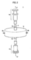
- FIG.2 is a schematic perspective view of the dielectric substance sealing apparatus 4
- FIG.3 is a schematic sectional view, taken along an X-X line, of the dielectric substance sealing apparatus 4 shown in FIG.2 .
- the dielectric substance sealing apparatus 4 includes a cavity resonator 10, a tube 12, a syringe 14a and a syringe 14b.
- a hole 16a and a hole 16b through which the tube 12 is passed are formed in center portions of upper and lower surfaces of the cavity resonator 10.
- a connector 20a and a connector 20b both are connected to the network analyzer 6 are formed on a side surface of the cavity resonator 10.
- a loop antenna 22a and a loop antenna 22b are formed on top end portions of the connector 20a and the connector 20b respectively.
- the tube 12 is used to seal a mixed substance 18 consisting of the powders and the liquid medium in the cavity resonator 10. In this case, it is preferable that the tube 12 should be formed of the material such as tetrafluoroethylene, or the like with a low dielectric constant and a small loss.
- the syringe 14a and the syringe 14b are used to inject the mixed substance 18 into the tube 12 and also fluidize the mixed substance 18 in the tube 12.
- the relative dielectric constant of the powders is measured as described in the following. First, a first measuring method out of the method of measuring the relative dielectric constant of powders will be explained hereunder.
- the relative dielectric constant of the liquid medium In the first measurement of the relative dielectric constant of powders, first either a liquid such as water, alcohol, or the like or a mixed substance in which water, alcohol, and the like are mixed is prepared as the liquid medium.
- the relative dielectric constant of this liquid medium can be changed if a ratio of the mixed liquid is changed.
- the relative dielectric constant of the liquid medium is measured by using the publicly-known liquid-medium relative-dielectric-constant measuring method such as the cavity resonator method, the S-parameter method, the capacitance method, or the like.
- the mixed substance 18 in which the powders as the measured object are mixed into the liquid medium is filled into the syringe 14a and the syringe 14b. Then, the syringe 14a is inserted into the tube 12, and then the mixed substance 18 is injected from the syringe 14a into the tube 12. Then, the syringe 14b is inserted into the tube 12 when the mixed substance 18 is filled in the tube 12.
- the dispersing agent should be mixed into the liquid medium to accelerate the dispersion of powders into the liquid medium.
- the mixed substance 18 injected into the tube 12 is fluidized in the tube 12 by moving pistons of the syringe 14a and the syringe 14b.
- the powders are diffused uniformly in the liquid medium by fluidizing the mixed substance 18 in the tube 12. As a result, improvement of a measuring precision of the relative dielectric constant of the powders can be achieved.
- the electromagnetic wave fed from the network analyzer 6 is input into the inside of the cavity resonator 10 from the loop antenna 22a.
- the electromagnetic wave fed from the cavity resonator 10 is output to the network analyzer 6 via the loop antenna 22b.
- a resonant frequency of the cavity resonator 10 is measured by using the electromagnetic wave that is output from the cavity resonator 10 to the network analyzer 6.
- the resonant frequency is output from the network analyzer 6 to the processing unit 8.
- the relative dielectric constant of the mixed substance 18 is calculated by the processing unit 8.
- the relative dielectric constant of the mixed substance 18 at a predetermined volume ratio of powders can be calculated by the processing unit 8.
- the relative dielectric constant of the mixed substance 18 with respect to the relative dielectric constant of each liquid medium is calculated by the processing unit 8.
- a graph showing a relationship between the relative dielectric constant of the liquid medium and the relative dielectric constant of the mixed substance 18 is made in the processing unit 8.
- the relative dielectric constant of the liquid medium is equal to the relative dielectric constant of the mixed substance 18 at an intersection point between a curve indicating the relative dielectric constant of the mixed substance 18 with respect to the relative dielectric constant of the liquid medium and the auxiliary line.
- the event that the relative dielectric constant of the liquid medium is equal to the relative dielectric constant of the mixed substance 18 is limited to the case that the relative dielectric constant of the liquid medium is equal to the relative dielectric constant of the powders.
- the relative dielectric constant of the liquid medium and the relative dielectric constant of the mixed substance 18, both having the same value, at the intersection point between the curve and the auxiliary line yield the relative dielectric constant of the powders.
- the relative dielectric constant of the powders is derived from the intersection point between the curve indicating the relative dielectric constant of the mixed substance 18 with respect to the relative dielectric constants of the liquid media that are estimated respectively based on the detected relative dielectric constant of the mixed substance 18, i.e., the relative dielectric constant of the mixed substance 18 that is derived by interpolating a plurality of measuring points of the mixed substance 18, and the auxiliary line.
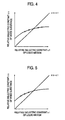
- FIG.5 is a graph showing another relationship between the relative dielectric constant of the liquid medium and the relative dielectric constant of the mixed substance 18.
- an abscissa denotes the relative dielectric constant of the liquid medium and an ordinate denotes the relative dielectric constant of the mixed substance 18.
- FIG.5 shows the method of deriving the relative dielectric constant of the powders when the relative dielectric constant of the powders cannot be detected from the intersection point between the curve indicating the detected relative dielectric constant of the mixed substance 18 and the relative dielectric constant of the mixed substance 18 obtained by the interpolation, i.e., the relative dielectric constant of the mixed substance 18 within the interpolation range, and the auxiliary line. More concretely, as shown in FIG.5 , the relative dielectric constant of the mixed substance 18 out of the interpolation range is estimated based on the relative dielectric constant of the mixed substance 18 within the interpolation range.
- the relative dielectric constant of the powders is detected from the intersection point between the curve of the relative dielectric constant of the mixed substance 18, which is derived by executing the extrapolation based on a plurality of measuring points of the mixed substance 18, and the auxiliary line.
- the relative dielectric constant of the powders can be detected by detecting the point at which the relative dielectric constant of the mixed substance 18 becomes equal to the relative dielectric constant of the liquid medium.
- the relative dielectric constant of powders can be detected with high precision.
- a second measuring method not being part of the present invention out of the method of measuring the relative dielectric constant of powders will be explained hereunder.
- a liquid medium such as an ion-exchange water, or the like is prepared.
- the mixed substance 18 in which the powders as the measured object are mixed into the liquid medium is filled in the syringe 14a and the syringe 14b.
- the syringe 14a is inserted into the tube 12, and then the mixed substance 18 is injected from the syringe 14a into the tube 12.
- the syringe 14b is inserted into the tube 12 when the mixed substance 18 is filled in the tube 12.
- the dispersing agent should be mixed into the liquid medium to accelerate the dispersion of the powders into the liquid medium.
- the mixed substance 18 injected into the tube 12 is fluidized in the tube 12 by moving the pistons of the syringe 14a and the syringe 14b.
- the powders are diffused uniformly in the liquid medium by fluidizing the mixed substance 18 in the tube 12. As a result, improvement of a measuring precision of the relative dielectric constant of the powders can be achieved.
- the electromagnetic wave fed from the network analyzer 6 is input into the inside of the cavity resonator 10 from the loop antenna 22a.
- the electromagnetic wave fed from the cavity resonator 10 is output to the network analyzer 6 via the loop antenna 22b.
- the resonant frequency of the cavity resonator 10 in a TM 010 mode is measured by using the electromagnetic wave that is output from the cavity resonator 10 to the network analyzer 6.
- the resonant frequency is output from the network analyzer 6 to the processing unit 8.
- the relative dielectric constant of the mixed substance 18 is calculated by the processing unit 8.
- the relative dielectric constant of the mixed substance 18 at a predetermined volume ratio of powders can be calculated by the processing unit 8.
- processing procedures executed up to now are similar to those in the above first measuring method.
- the relative dielectric constant of the mixed substance 18 is derived by the processing unit 8 while changing gradually the volume ratio of the powders occupied in the mixed substance 18 that is injected into the tube 12.
- the processing unit 8 applies the formula such as the logarithmic mixture rule, the Lichtenecker-Rother's Formula, or the like, which is used to calculate the relative dielectric constants of powders from the relative dielectric constant of the mixed substance 18, to the relative dielectric constant of the mixed substance 18 calculated in this manner to calculate the relative dielectric constants of powders.
- the formula such as the logarithmic mixture rule, the Lichtenecker-Rother's Formula, or the like, which is used to calculate the relative dielectric constants of powders from the relative dielectric constant of the mixed substance 18, to the relative dielectric constant of the mixed substance 18 calculated in this manner to calculate the relative dielectric constants of powders.
- a graph showing a relationship between the volume ratio of the powders and the relative dielectric constant of the mixed substance 18 is made in the processing unit 8.
- FIG.6 is a graph obtained by fitting the logarithmic mixture rule to a relationship between the volume ratio of the powders and the relative dielectric constant of the mixed substance 18 based on the method of least squares.
- an abscissa denotes the volume ratio of powders and an ordinate denotes the relative dielectric constant of the mixed substance 18.
- the fact that the volume ratio of the powders is 1.0 signifies that the liquid medium is not present in the mixed substance 18 and merely the powders are present. Therefore, a value of the relative dielectric constant obtained when the volume ratio of the powders is 1.0 corresponds to the relative dielectric constant of the powders. Thus, the relative dielectric constant of the powders is detected by reading the value of the relative dielectric constant obtained when the volume ratio of powders is 1.0 from the curve shown in FIG.6 .
- the curve shown in FIG.6 is plotted by detecting the relative dielectric constant of the mixed substance 18 with respect to the volume ratio of the powders by estimating the relative dielectric constant of the mixed substance 18 out of the measuring range based on the detected relative dielectric constant of the mixed substance 18, i.e., by detecting the relative dielectric constant of the mixed substance 18 by extrapolating a plurality of measuring points of the mixed substance 18.
- the fact that the volume ratio of the powders is 0. 0 signifies that no powder is present in the mixed substance 18 and merely the liquid medium is present. Therefore, a value of the relative dielectric constant obtained when the volume ratio of powders is 0.0 gives the relative dielectric constant of the liquid medium. For this reason, in case the relative dielectric constant of the liquid medium is extremely lower or higher than the relative dielectric constant of the powders, a change of a gradient of the curve become steep. Thus, it is possible that a measuring precision of the relative dielectric constant of the powders derived by the extrapolation is worsened.
- the liquid medium having a value of the relative dielectric constant close to a value of the detected relative dielectric constant of powders it is possible to prevent the deterioration of the measuring precision when the relative dielectric constant of powders is derived by the extrapolation.
- a value of the relative dielectric constant of the ceramic composition made of the measured powders is employed. If the liquid medium having the relative dielectric constant that is 0.5 times to 2.0 times the relative dielectric constant of the ceramic composition made of the powders is selected, a measuring precision of the relative dielectric constant of the powders can be improved.
- log ⁇ ⁇ r vo ⁇ 1 ⁇ log ⁇ ⁇ r ⁇ 1 + v ⁇ 2 ⁇ log ⁇ ⁇ r ⁇ 2
- ⁇ r k v ⁇ 1 ⁇ ⁇ r ⁇ 1 k + v ⁇ 2 ⁇ ⁇ r ⁇ 2 k
- the relative dielectric constant of powders can be detected by using the liquid medium a value of the relative dielectric constant of which is close to a value of the detected relative dielectric constant of powders.
- the relative dielectric constant of powders can be derived with high precision.
- the mixed substance 18 injected into the tube 12 is fluidized by using the syringe 14a and the syringe 14b.
- the mixed substance 18 may be fluidized by using a fluidizing apparatus 38A shown in FIG.7 .
- FIG.7 is a schematic view showing a fluidizing apparatus 38A using a pump.
- the fluidizing apparatus 38A shown in FIG. 7 fluidizes the mixed substance 18 by circulating this mixed substance 18 by using a pump 40.
- the powders in the mixed substance 18 can be diffused uniformly by using the fluidizing apparatus 38A shown in FIG. 7 . As a result, improvement of the measuring precision of the relative dielectric constant of the powders can be attained.
- FIG.8 is a sectional view of a measuring system for implementing the method of measuring the relative dielectric constant of powders according another example of the present invention.
- a measuring system 30 includes the network analyzer 6, the processing unit 8, a probe 32, a cable 34, and a vessel 36.
- the network analyzer 6 and the processing unit 8 are same as those constituting the measuring system 2.
- the probe 32 is a coaxial cable that inputs the electromagnetic wave fed from the network analyzer 6 into the mixed substance 18 contained in the vessel 36. This probe 32 is connected to the network analyzer 6 via the cable 34.
- the relative dielectric constant of the powders is measured as described in the following.
- the liquid such as water, alcohol, or the like or the mixed substance in which water, alcohol, and the like are mixed is prepared as the liquid medium.
- the relative dielectric constant of the liquid medium is measured by using the publicly-known liquid-medium relative-dielectric-constant measuring method such as the cavity resonator method, the S-parameter method, the capacitance method, or the like.
- the mixed substance 18 in which the powders as the measured object are mixed in the liquid medium is contained into the vessel 36.
- the electromagnetic wave fed from the network analyzer 6 is input into the mixed substance 18 from the probe 32 via the cable 34.
- such electromagnetic wave is output to the network analyzer 6 from the probe 32 via the cable 34.
- a reflection coefficient between an end surface of the probe 32 and the mixed substance 18 is measured based on the electromagnetic wave that is output from the probe 32 to the network analyzer 6.
- the reflection coefficient is output to the processing unit 8 from the network analyzer 6 as the measured result.
- the relative dielectric constant of the mixed substance 18 is calculated in the processing unit 8.
- the relative dielectric constant of powders can be derived by using the probe 32. Therefore, the relative dielectric constant of powders can be detected with high precision.
- the mixed substance 18 contained in the vessel 36 is circulated by using the ultrasonic wave, but such mixed substance 18 may be circulated by using a circulating apparatus 38B shown in FIG.9.
- FIG.9 is a schematic view showing the circulating apparatus 38B using stirring blades.
- the fluidizing apparatus 38B fluidizes the mixed substance 18 by causing stirring blades 44 connected to a motor 42 to rotate.
- the powders in the mixed substance 18 can be diffused uniformly by using the fluidizing apparatus 38B shown in FIG. 9 . As a result, improvement of a measuring precision of the relative dielectric constant of powders can be attained.
- Al 2 O 3 powders were prepared as the sample of the powder dielectric substance, and a mixed substance in which the ion-exchange water and the alcohol are mixed was prepared as the liquid medium. Also, the measuring system 2 shown in FIG.1 was employed as the measuring system.
- the mixed substance 18 in which the sample as the measured object is mixed in the liquid substance was prepared, and then filled in the syringe 14a and the syringe 14b.
- the volume ratio of the powders in the sample was set to 0.1 in the mixed substance 18.
- the relative dielectric constant of the liquid medium was measured by using the cavity resonator method.
- the syringe 14a was inserted into the tube 12 and then the mixed substance 18 was injected into the tube 12.
- the syringe 14b was inserted into the tube 12 when the mixed substance 18 was filled in the tube 12.
- the mixed substance 18 injected into the tube 12 was fluidized in the tube 12 by moving the pistons of the syringe 14a and the syringe 14b.
- a cavity resonator having a diameter of 80 mm and a height of 10 mm was used as the cavity resonator 10
- a tube made of tetrafluoroethylene to have an inner diameter of 1 mm and an outer diameter of 3 mm was used as the tube 12.
- the electromagnetic wave of 2.5 to 3.0 GHz fed from the network analyzer 6 was input into the cavity resonator 10 from the loop antenna 22a.
- such electromagnetic wave fed from the cavity resonator 10 was output to the network analyzer 6 via the loop antenna 22b.
- the resonant frequency of the cavity resonator 10 in a TM 010 mode was measured by the network analyzer 6 based on the electromagnetic wave that was output from the cavity resonator 10 to the network analyzer 6.
- the resonant frequency was 2.86 GHz.
- the resonant frequency was output from the network analyzer 6 to the processing unit 8 as the measured result, and then the relative dielectric constant of the mixed substance 18 was calculated by the processing unit 8.
- a graph showing a relationship between the relative dielectric constant of the liquid medium and the relative dielectric constant of the mixed substance 18 was made in the processing unit 8.
- FIG.10 is a graph showing the relationship between the relative dielectric constant of the liquid medium and the relative dielectric constant of the mixed substance 18.
- an abscissa denotes the relative dielectric constant of the liquid medium and an ordinate denotes the relative dielectric constant of the mixed substance 18.
- sample A Four types of powders consisting of sample A, sample B, sample C, and sample D respectively were prepared as the samples. All these powders were made of Ba (NdBi) 2 TiO 4 .
- the sample A was formed by breaking tentatively sintered powders
- the sample B was formed of spherical powders
- the sample C was formed of spherical powders
- the sample D was formed by breaking the sample C.
- the liquid medium of the sample the mixed substance in which the ion-exchange water, the alcohol, and the 0.3 wt% dispersing agent are mixed was prepared.
- a volume ratio of the sample A in the mixed substance 18 was set to 0.2
- a volume ratio of the sample B was set to 0.2
- a volume ratio of the sample C was set to 0.4
- a volume ratio of the sample D was set to 0.4.
- the mixed substances 18 in which the sample A, the sample B, the sample C, and the sample D as the measured object are mixed in the liquid medium respectively were prepared. Then, the relative dielectric constants of respective mixed substances 18 were calculated by using the measuring system 2 shown in FIG.1 as the measuring system. In Example 2, the relative dielectric constants of the mixed substances 18 containing the sample A, the sample B, the sample C, and the sample D respectively were calculated while changing the relative dielectric constant of the liquid medium in a range from 66 to 77.
- the relative dielectric constants of the sample A, the sample B, the sample C, and the sample D were calculated by reading the relative dielectric constant of the liquid medium and the relative dielectric constant of the mixed substance 18 at the intersection point between the curve and the auxiliary line, in the same way as in Example 1.
- the relative dielectric constant of the sample A was calculated as 82.22
- the relative dielectric constant of the sample B was calculated as 77.71
- the relative dielectric constant of the sample C was calculated as 77.34
- the relative dielectric constant of the sample D was calculated as 79.78.
- Example 3 the same samples as in Example 2, i.e., four types of powder dielectric substances consisting of the sample A, the sample B, the sample C, and the sample D respectively were prepared as the samples.
- the liquid medium in the sample the mixed substance in which BaTiO 3 powders and the dispersing agent are mixed in the ion-exchange water was prepared.
- a volume ratio of the sample A in the mixed substance 18 was set to 0.2
- a volume ratio of the sample B was set to 0.2
- a volume ratio of the sample C was set to 0.4
- a volume ratio of the sample D was set to 0.4.
- the mixed substances 18 in which the sample A, the sample B, the sample C, and the sample D as the measured object are mixed in the liquid medium respectively were prepared, like Example 2. Then, the relative dielectric constants of respective mixed substances 18 were calculated by using the measuring system 2 shown in FIG.1 as the measuring system. In Example 3, the relative dielectric constants of the mixed substances 18 containing the sample A, the sample B, the sample C, and the sample D respectively were calculated while changing the relative dielectric constant of the liquid medium in a range from 74 to 96.
- FIG.12 is a graph showing a relationship between the relative dielectric constant of the liquid medium and the relative dielectric constant of the mixed substance 18. Also, in FIG. 12 , an abscissa denotes the relative dielectric constant of the liquid medium and an ordinate denotes the relative dielectric constant of the mixed substance 18.
- the relative dielectric constants of the sample A, the sample B, the sample C, and the sample D were calculated by reading the relative dielectric constant of the liquid medium and the relative dielectric constant of the mixed substance 18 at the intersection point between the curve and the auxiliary line, in the same way as in Example 1.
- the relative dielectric constant of the sample A was calculated as 88.71
- the relative dielectric constant of the sample B was calculated as 77.80
- the relative dielectric constant of the sample C was calculated as 78.04
- the relative dielectric constant of the sample D was calculated as 80.32.
- Example 2 and Example 3 calculated results of the relative dielectric constants of the sample A, the sample B, the sample C, and the sample D are given in Table 1. TABLE 1 sample A sample B sample C sample D Example 2 82.22 77.71 77.34 79.78 Example 3 88.71 77.80 78.04 80.32
- sample A Three types of powders consisting of sample A, sample B, and sample C respectively were prepared as the samples. All these powders were made of Ba (NdBi) 2 TiO 4 .
- the sample A was formed by breaking the tentatively sintered powders, the sample B was formed of the spherical powders, and the sample C was formed by breaking the sample B.
- the mixed substance consisting of the 99.7 wt% ion-exchange water and the 0.3 wt% dispersing agent was prepared.
- the measuring system 2 shown in FIG.1 was employed as the measuring system.
- the relative dielectric constant of the ceramic composition in the sample was 93 and the relative dielectric constant of the liquid medium was 74.
- the relative dielectric constant of the liquid medium was 0.80 times the relative dielectric constant of the ceramic composition powders.
- the mixed substance 18 in which the sample A as the measured object is mixed in the liquid medium was prepared and then filled in the syringe 14a and the syringe 14b.
- the mixed substance 18 was prepared in such a manner that the volume ratio of the powders in the sample A became 0.4.
- the syringe 14a was inserted into the tube 12 and then the mixed substance 18 was injected into the tube 12.
- the syringe 14b was inserted into the tube 12 when the mixed substance 18 was filled in the tube 12.
- the mixed substance 18 injected into the tube 12 was fluidized in the tube 12 by moving the pistons of the syringe 14a and the syringe 14b.
- the cavity resonator having a diameter of 80 mm and a height of 10 mm was used as the cavity resonator 10
- the tube formed of tetrafluoroethylene to have an inner diameter of 1 mm and an outer diameter of 3 mm was used as the tube 12.
- the electromagnetic wave of 2.5 to 3.0 GHz fed from the network analyzer 6 was input into the cavity resonator 10 from the loop antenna 22a.
- such electromagnetic wave fed from the cavity resonator 10 was output to the network analyzer 6 via the loop antenna 22b.
- the resonant frequency of the cavity resonator 10 in a TM 010 mode was measured by the network analyzer 6 based on the electromagnetic wave that was output from the cavity resonator 10 to the network analyzer 6.
- the resonant frequency was 2.86 GHz.
- the resonant frequency was output from the network analyzer 6 to the processing unit 8 as the measured result, and then the relative dielectric constant of the mixed substance 18 was calculated by the processing unit 8.
- the relative dielectric constant of the mixed substance 18 was calculated in the same way as the case that the volume ratio of the sample A was 0.4.
- a graph showing a relationship between the volume ratio of the powders and the relative dielectric constant of the mixed substance 18 was made in the processing unit 8.
- FIG.13 is a graph obtained by fitting the logarithmic mixture rule to the relationship between the volume ratio of the powders and the relative dielectric constant of the mixed substance 18 based on the method of least squares. Also, in FIG.13 , an abscissa denotes the volume ratio of the powders and an ordinate denotes the relative dielectric constant of the mixed substance 18.
- FIG.14 is a graph obtained by fitting the Lichtenecker-Rother' s Formula to the relationship between the volume ratio of the powders and the relative dielectric constant of the mixed substance 18 based on the method of least squares. Also, in FIG.14 , an abscissa denotes the volume ratio of the powders and an ordinate denotes the relative dielectric constant of the mixed substance 18.
- the relative dielectric constant of the sample A was detected by reading a value of the relative dielectric constant when the volume ratio of the powders is 1.0. Also, in FIG.14 , the relative dielectric constant of the sample A was detected by reading a value of the relative dielectric constant when the volume ratio of the powders is 1.0.
- the spherical powders made of Ba (NdBi) 2 TiO 4 were prepared.
- the liquid medium the mixed substance in which the 15.65 wt% BaTiO 3 powders and the 0.3 wt% dispersing agent are mixed in the 84.10 wt% ion-exchange water was prepared.
- the mixed substance 18 in which the sample as the measured object is mixed in the liquid medium, in which the ion-exchange water, the BaTiO 3 powders and the dispersing agent are mixed was prepared.
- the relative dielectric constant of the mixed substance 18 was calculated by using the measuring system 2 shown in FIG.1 as the measuring system.
- the relative dielectric constant of the ceramic composition in the sample was 93 and the relative dielectric constant of the liquid medium was 80.1.
- the relative dielectric constant of the liquid medium was 0.86 times the relative dielectric constant of the ceramic composition powders.
- Example 5 the relative dielectric constant of the mixed substance 18 was detected while changing gradually the volume ratio of the sample occupied in the mixed substance 18 in a range from 0 to 0.4.
- a graph showing a relationship between the volume ratio of the powders and the relative dielectric constant of the mixed substance 18 was made in the processing unit 8.
- FIG.15 is a graph obtained by fitting the logarithmic mixture rule to the relationship between the volume ratio of the powders and the relative dielectric constant of the mixed substance 18 based on the method of least squares.
- an abscissa denotes the volume ratio of the powders and an ordinate denotes the relative dielectric constant of the mixed substance 18.
- FIG.16 is a graph obtained by fitting the Lichtenecker-Rother' s Formula to the relationship between the volume ratio of the powders and the relative dielectric constant of the mixed substance 18 based on the method of least squares.
- an abscissa denotes the volume ratio of the powders and an ordinate denotes the relative dielectric constant of the mixed substance 18.
- the relative dielectric constant of the sample was detected by reading a value of the relative dielectric constant when the volume ratio of the powders is 1.0. Also, in FIG.16 , the relative dielectric constant of the sample was detected by reading a value of the relative dielectric constant when the volume ratio of the powders is 1.0.
- the Al 2 O 3 powders were prepared.
- the liquid medium the mixed substance in which the ion-exchange water and methanol are mixed was prepared.
- Five types of liquid media consisting of the liquid medium A (relative dielectric constant 10.23), the liquid medium B (same 14.08), the liquid medium C (same 18.26), the liquid medium D (same 22.88), and the liquid medium E (same 41.69) were prepared while changing an amount of methanol that is mixed into the ion-exchange water.
- the relative dielectric constant of the mixed substance 18 was calculated by employing the measuring system 2 shown in FIG.1 as the measuring system. Now, the relative dielectric constant of the ceramic composition of the sample was 11. Thus, the relative dielectric constants of five type liquid media were 0.93 times (liquid mediumA) , 1.28 times (liquid medium B) , 1.66 times (liquid medium C), 2.08 times (liquid medium D), and 3.79 times (liquid medium E) the ceramic composition of the sample respectively.
- Example 6 the relative dielectric constant of the mixed substance 18 was detected while changing gradually the volume ratio of the sample occupied in the mixed substance 18 to the liquid medium A in a range from 0 to 0.2.
- a graph showing a relationship between the volume ratio of the powders and the relative dielectric constant of the mixed substance 18 was made in the processing unit 8.
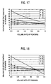
- FIG.17 is a graph obtained by fitting the logarithmic mixture rule to the relationship between the volume ratio of the powders and the relative dielectric constant of the mixed substance 18 based on the method of least squares.
- an abscissa denotes the volume ratio of the powders and an ordinate denotes the relative dielectric constant of the mixed substance 18.
- FIG.18 is a graph obtained by fitting the Lichtenecker-Rother' s Formula to the relationship between the volume ratio of the powders and the relative dielectric constant of the mixed substance 18 based on the method of least squares.
- an abscissa denotes the volume ratio of the powders and an ordinate denotes the relative dielectric constant of the mixed substance 18.
- the relative dielectric constant of the sample was detected by reading a value of the relative dielectric constant when the volume ratio of the powders is 1.0. Also, in FIG.18 , the relative dielectric constant of the sample was detected by reading a value of the relative dielectric constant when the volume ratio of the powders is 1.0.
- the relative dielectric constants of the samples detected with respect to the liquid media A, B, C by using the logarithmic mixture rule and the Lichtenecker-Rother's Formula became almost equal mutually.
- the relative dielectric constants of the liquid media were 0.93 times (liquid medium A), 1.28 times (liquid medium B), and 1.66 times (liquid medium C) the relative dielectric constant of the ceramic composition of the sample respectively.
- the relative dielectric constant of powders can be obtained with high precision when the relative dielectric constant of the mixed substance with respect to the ceramic composition of the sample ranges over 0.93 times to 1.66 times.
- the TM 010 mode is used as the resonant mode when the resonant frequency is measured.
- the cavity resonator is formed cylindrically.
- the cavity resonator may be formed as square, rectangle, triangle, or the like.
- the ion-exchange water is used as the liquid medium.
- the liquid except the ion-exchange water or the mixed substance containing the liquid and the powder dielectric substance may be used as the liquid medium.
- the mixed substance 18 injected into the tube 12 is fluidized by using the syringe 14a and the syringe 14b. But the mixed substance 18 maybe fluidized by using the fluidizing apparatus 38A shown in FIG.7 .
- the mixed substance 18 injected into the tube 12 is fluidized by using the syringe 14a and the syringe 14b.
- the mixed substance 18 may be fluidized by using the fluidizing apparatus 38A shown in FIG. 7 .
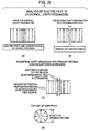
- FIG.20(a) shows the distribution of the electric field in the TM 010 mode in the ideal cylindrical cavity resonator, and the electric fields each indicated with an arrow are concentrated at a center portion of the cylinder. Then, the dielectric substance as the measured object is placed at the maximum electric field point of the resonator.
- the TM 010 mode cylindrical cavity resonator used in measurement of the relative dielectric constant of powders in the present invention should be formed as a closed cylinder.
- FIG. 19(b) it is made possible by a structure in which an opening portion is provided to one of center portions of the resonator, to take out the dielectric substance as the measured object.
- the electromagnetic wave leaks out from the inside of the resonator to the outside via the opening portion in the structure in which the opening portion is formed in the resonator, as shown in FIG.19(b) .
- measurement of the resonant frequency or the unloaded Q value becomes unstable due to the leakage of the electromagnetic wave, which has an influence upon measurement of the dielectric constant and the dielectric loss tangent.
- FIG.19 (c) (d) it is effective to provide a supporter on the outside of the opening portion.
- FIG.19(c) shows an example in which the supporter is provided on the outside of the opening portion when the opening portion is provided to one of the center portions of the resonator.
- FIG.19(d) shows an example in which the supporter is provided on the outside of both opening portions when the opening portion is provided to both of the center portions of the resonator.
- FIG. 19 (c) (d) when the opening portion of the supporter portion is constructed sufficiently smaller than a diameter of the resonator, such supporter portion can act as a cut-off region.
- a cut-off frequency of the supporter portion (TM 010 mode) is shown in FIG.21 . It is appreciated from FIG.21 that the cut-off frequency becomes higher when a length of the opening portion becomes shorter. If a difference between the resonant frequency of the resonator and the cut-off frequency of the supporter portion is increased larger, the cut-off characteristic is excellent and therefore the leakage of the electromagnetic wave from the resonator can be suppressed.
- a distribution of the electric field when the supporters are provided as shown in FIG.19(d) is shown in FIG.20(c) .
- a diameter is set to a length of the opening portion, as shown in FIG. 20 (d) , when the opening portion is circular.
- the longest portion of the opening portion is set to the length of the opening portion when the opening portion has a shape other than the circle.
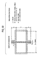
- FIG.22 is a view showing conditions required for a resonator shape to execute the simulation to detect the optimum value of the supporter of the cylindrical cavity resonator.
- the resonant frequency is simulated by setting shapes of respective portions of the resonator and the dielectric constant of the dielectric substance, as shown in FIG.22 .
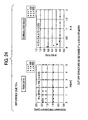
- FIG.24(b) is a graph showing normalized data of the same. It is seen from FIG.24 (b) that the cut-off structure can be obtained if h/d is in excess of 0.5.
- FIG. 25 (b) is a graph showing normalized data of the same. It is seen from FIG. 25 (b) that the cut-off structure can be obtained if h/d is in excess of 0.5.
- FIG.26(b) is a graph showing normalized data of the same. It is seen from FIG.26 (b) that the cut-off structure can be obtained if h/d is in excess of 0.5. In this case, the above simulation is applied to the resonator in FIG.22 .
- results of the above simulation can be substantially applied to the case that the shape of the resonator and the shape of the opening portion are varied.
- the cavity resonator of the present invention is not limited to the application of the powders, and may be applied to any measured sample if such measured sample is formed of the dielectric substance.
- the relative dielectric constant of the mixed substance 18 is detected by inputting the electromagnetic wave into the cavity resonator and then measuring the resonant frequency based on the replied electromagnetic wave.
- the relative dielectric constant of the mixed substance may be detected by applying a voltage into a vessel in which a pair of electrodes are arranged and the mixed substance is filled.
- the relative dielectric constant of the mixed substance may be detected by inputting the electromagnetic wave into a rectangular waveguide and then measuring a transmission coefficient and a reflection coefficient of the replied electromagnetic wave.
- the TM 010 mode is used as the resonance mode applied when the resonant frequency is measured.
- the relative dielectric constant of the liquid substance may be measured by using the measuring system 2.
- the cavity resonator is formed cylindrically. But the cavity resonator may be shaped into the square, the rectangle, the triangle, or the like.
- the relative dielectric constant of the mixed substance is measured by changing the relative dielectric constant of the liquid substance in the situation that the volume ratio of the powders is kept constant.
- the relative dielectric constant of the mixed substance 18 can be measured by using either the logarithmic mixture rule or Lichtenecker-Rother's Formula.
- the liquid such as water, alcohol, or the like or the mixed substance in which water, alcohol, and the like are mixed is employed as the liquidmedium.
- the liquid except the water or the alcohol, their mixed substance, or the mixed substance consisting of the liquid and the powder dielectric substance may be employed as the liquid medium.
- the mixed substance 18 injected into the tube 12 is fluidized by using the syringe 14a and the syringe 14b. But the mixed substance 18 maybe fluidized by using the fluidizing apparatus 38A shown in FIG.7 .
- the TM 010 mode in the cavity resonator can be applied to a following system by utilizing the characteristics that the mode is the lowest mode (which has the lowest resonant frequency out of an infinite number of resonance peaks) and the electric filed are concentrated at a center axis of the cavity resonator.
- the dielectric substance measuring system for inserting the rod-like-shaped dielectric substance into the electric-field concentrated portion on the center axis of the cavity resonator to which the supporter is provided, then measuring the resonant frequency and the unloaded Q value of the cavity resonator, and then measuring the relative dielectric constant and the dielectric loss tangent of the inserted rod-like dielectric substance based on the measured results can be implemented.
- the TM 010 mode in the cavity resonator to which the supporter is provided is the lowest mode, the resonator or the filter that is excellent in the spurious characteristics can be implemented.
- the rod-like-shaped dielectric substance is inserted into the electric-field concentrated portion on the center axis of the cavity resonator to which the supporter is provided, the intended resonance characteristic can be attained.
Landscapes
- Physics & Mathematics (AREA)
- General Physics & Mathematics (AREA)
- Electromagnetism (AREA)
- Health & Medical Sciences (AREA)
- Life Sciences & Earth Sciences (AREA)
- Chemical & Material Sciences (AREA)
- Analytical Chemistry (AREA)
- Biochemistry (AREA)
- General Health & Medical Sciences (AREA)
- Immunology (AREA)
- Pathology (AREA)
- Measurement Of Resistance Or Impedance (AREA)
- Investigating Or Analyzing Materials By The Use Of Electric Means (AREA)
Claims (6)
- Verfahren zum Messen einer relativen Dielektrizitätskonstante eines Pulvers, gekennzeichnet durch die folgenden Schritte:Bereitstellen einer gemischten Substanz (18), die das Pulver und ein flüssiges Medium in einem vorgegebenen Volumenverhältnis von Flüssigkeit und Pulver umfasst, wobei das flüssige Medium ein Gemisch aus einer ersten Flüssigkeit und einer zweiten Flüssigkeit umfasst,Messen einer relativen Dielektrizitätskonstante der gemischten Substanz (18),allmähliches Ändern der relativen Dielektrizitätskonstante des flüssigen Mediums bei dem gleichen Volumenverhältnis von Flüssigkeit und Pulver und Berechnen der relativen Dielektrizitätskonstante der gemischten Substanz (18) in Bezug auf die relative Dielektrizitätskonstante des flüssigen Mediums, wobei die relative Dielektrizitätskonstante des flüssigen Mediums geändert wird, indem das Mischungsverhältnis der ersten und der zweiten Flüssigkeit geändert wird, undBestimmen der relativen Dielektrizitätskonstante der gemischten Substanz (18) oder einer relativen Dielektrizitätskonstante des flüssigen Mediums als die relative Dielektrizitätskonstante des Pulvers, wenn die relative Dielektrizitätskonstante der gemischten Substanz (18) der relativen Dielektrizitätskonstante des flüssigen Mediums gleich ist.
- Verfahren zum Messen einer relativen Dielektrizitätskonstante eines Pulvers nach Anspruch 1, das des Weiteren umfasst:Einschließen der gemischten Substanz (18) in einem Resonator (10);Einleiten einer elektromagnetischen Welle in den Resonator (10) und dann Berechnen der relativen Dielektrizitätskonstante der gemischten Substanz (18) auf Basis von Verhalten der elektromagnetischen Welle.
- Verfahren zum Messen einer relativen Dielektrizitätskonstante eines Pulvers nach Anspruch 1, das des Weiteren umfasst:Einleiten einer elektromagnetischen Welle in einen Behälter (36), in den die gemischte Substanz (18) gefüllt ist, undBerechnen einer relativen Dielektrizitätskonstante der gemischten Substanz (18) auf Basis eines Verhaltens der elektromagnetischen Welle.
- Verfahren zum Messen einer relativen Dielektrizitätskonstante eines Pulvers nach einem der Ansprüche 1 bis 3, wobei
die gemischte Substanz (18) die erste und die zweite Flüssigkeit, eine pulverförmige dielektrische Substanz und ein Dispergiermittel enthält. - Verfahren zum Messen einer relativen Dielektrizitätskonstante eines Pulvers nach einem der Ansprüche 1 bis 4, wobei
die relative Dielektrizitätskonstante des flüssigen Mediums das 0,5-fache oder mehr der relativen Dielektrizitätskonstante des Pulvers beträgt. - Verfahren zum Messen einer relativen Dielektrizitätskonstante eines Pulvers nach einem der Ansprüche 1 bis 5, wobei
die relative Dielektrizitätskonstante des flüssigen Mediums das 0,5-fache bis 2,0-fache der relativen Dielektrizitätskonstante des Pulvers beträgt.
Applications Claiming Priority (6)
| Application Number | Priority Date | Filing Date | Title |
|---|---|---|---|
| JP2003372581 | 2003-10-31 | ||
| JP2003372581 | 2003-10-31 | ||
| JP2003375478 | 2003-11-05 | ||
| JP2003375478 | 2003-11-05 | ||
| JP2004078519 | 2004-03-18 | ||
| JP2004078519A JP4729856B2 (ja) | 2003-10-31 | 2004-03-18 | 粉体の誘電体の比誘電率の測定方法 |
Publications (2)
| Publication Number | Publication Date |
|---|---|
| EP1528618A1 EP1528618A1 (de) | 2005-05-04 |
| EP1528618B1 true EP1528618B1 (de) | 2010-12-15 |
Family
ID=34426701
Family Applications (1)
| Application Number | Title | Priority Date | Filing Date |
|---|---|---|---|
| EP04023517A Expired - Lifetime EP1528618B1 (de) | 2003-10-31 | 2004-10-01 | Verfahren zur Messung der relativen Dielektrizitätskonstante einer dielektrischen Pulversubstanz, dazu verwendeter Hohlraumresonator und Anwendungsvorrichtung |
Country Status (7)
| Country | Link |
|---|---|
| US (2) | US7199591B2 (de) |
| EP (1) | EP1528618B1 (de) |
| JP (1) | JP4729856B2 (de) |
| KR (1) | KR100703241B1 (de) |
| CN (1) | CN1641370B (de) |
| DE (1) | DE602004030529D1 (de) |
| TW (1) | TWI244552B (de) |
Families Citing this family (31)
| Publication number | Priority date | Publication date | Assignee | Title |
|---|---|---|---|---|
| ES2255388B1 (es) * | 2004-05-14 | 2008-02-01 | Universidad Politecnica De Valencia | Sensor de microondas y metodo para medir la degradacion de los componentes fluidos de suelas de calzado. |
| JP2007047072A (ja) * | 2005-08-11 | 2007-02-22 | Murata Mfg Co Ltd | 誘電率測定装置及び誘電率測定方法 |
| JP2007263625A (ja) * | 2006-03-27 | 2007-10-11 | Hokkaido Univ | 複素誘電率測定装置および複素誘電率測定方法 |
| JP5132145B2 (ja) * | 2006-12-26 | 2013-01-30 | 京セラ株式会社 | 粉体の誘電率測定方法 |
| US7821269B2 (en) * | 2007-06-08 | 2010-10-26 | Vladimir Petrovsky | Method for determining the dielectric constant of particles |
| JP2009222673A (ja) * | 2008-03-18 | 2009-10-01 | Panasonic Corp | 粉体物性測定方法および粉体物性測定装置 |
| CN101957404B (zh) * | 2009-07-20 | 2013-08-14 | 中国科学院遥感应用研究所 | 一种粮堆介电常数的微波测量方法 |
| GB2492144B (en) | 2011-06-23 | 2013-10-30 | Schlumberger Holdings | Matrix permittivity determination |
| RU2474830C1 (ru) * | 2011-08-12 | 2013-02-10 | Федеральное государственное бюджетное образовательное учреждение высшего профессионального образования "Омский государственный педагогический университет" (ОмГПУ) | Способ измерения комплексной диэлектрической проницаемости жидких и сыпучих веществ в широком диапазоне частот |
| RU2509315C2 (ru) * | 2012-05-11 | 2014-03-10 | Федеральное государственное бюджетное образовательное учреждение высшего профессионального образования "Омский государственный педагогический университет" ОмГПУ | Способ измерения комплексной диэлектрической проницаемости жидких и сыпучих веществ |
| CN102818937A (zh) * | 2012-09-08 | 2012-12-12 | 苏州大学 | 一种测量固体物质介电常数的方法 |
| CN103323678B (zh) * | 2013-06-07 | 2015-08-12 | 中国水电顾问集团贵阳勘测设计研究院 | 一种现场测试岩土体相对介电常数的方法 |
| US9234925B2 (en) * | 2013-06-10 | 2016-01-12 | Korea Advanced Institute Of Science And Technology | Apparatus and method for measuring dielectric constant |
| CN112362973A (zh) | 2014-06-06 | 2021-02-12 | 滤波器感知技术有限公司 | 射频状态变量测量系统和方法 |
| WO2016003445A1 (en) * | 2014-07-01 | 2016-01-07 | Hewlett-Packard Development Company, L.P. | Estimating circuit board characteristics |
| KR101461227B1 (ko) * | 2014-07-11 | 2014-11-18 | 김광연 | 파이프 내면에 퇴적된 파우더의 두께를 측정하는 장치 및 방법 |
| CN104950184B (zh) * | 2015-06-04 | 2017-08-11 | 电子科技大学 | 固体及粉末材料的宽频带变温介电常数测试系统 |
| CN108139346B (zh) | 2015-10-15 | 2020-06-23 | 白石工业株式会社 | 计算颗粒分散复合材料的介电常数的方法和分散性评价方法 |
| CN105629078A (zh) * | 2015-12-24 | 2016-06-01 | 河南师范大学 | 一种微量液体介电常数测试传感器 |
| CN105929240B (zh) * | 2016-05-04 | 2018-11-23 | 南京大学 | 测量高温超导薄膜表面本征阻抗的谐振器装置及测量方法 |
| EP3492911B1 (de) * | 2017-11-29 | 2025-04-16 | Heraeus Quarzglas GmbH & Co. KG | Verfahren zur bestimmung der konzentration einer zusatzkomponente in einem körper aus keramischem oder glasigem werkstoff |
| US10542906B2 (en) | 2018-04-25 | 2020-01-28 | Spectrohm, Inc. | Tomographic systems and methods for determining characteristics of inhomogenous specimens using guided electromagnetic fields |
| US12228535B2 (en) | 2018-04-25 | 2025-02-18 | Spectrohm, Inc. | Methods for determining regional impedance characteristics of inhomogenous specimens using guided electromagnetic fields |
| KR102164927B1 (ko) | 2019-06-17 | 2020-10-13 | 동의대학교 산학협력단 | 손실결합 공동공진기의 q 측정방법 |
| JP7471587B2 (ja) * | 2020-05-20 | 2024-04-22 | Emラボ株式会社 | 分割型直方体共振器およびそれを用いた誘電率の測定方法 |
| JP7612394B2 (ja) * | 2020-11-17 | 2025-01-14 | 旭化成株式会社 | 検査装置 |
| CN112526218B (zh) * | 2020-11-19 | 2021-10-15 | 华中科技大学 | 一种液体相对介电常数的测量方法及系统 |
| CN112444681B (zh) * | 2020-11-30 | 2022-07-15 | 山东国瓷功能材料股份有限公司 | 介电材料测试系统、方法、装置及平台 |
| CN113655287A (zh) * | 2021-08-05 | 2021-11-16 | 华南理工大学 | 平面介质介电常数宽频带测试结构及其测试方法 |
| TWI783719B (zh) * | 2021-10-07 | 2022-11-11 | 南亞塑膠工業股份有限公司 | 計算高分子材料的介電常數及介電損耗的方法 |
| US20250070443A1 (en) * | 2021-12-28 | 2025-02-27 | The Curators Of The University Of Missouri | Transverse magnetic mode split post dielectric resonator |
Family Cites Families (28)
| Publication number | Priority date | Publication date | Assignee | Title |
|---|---|---|---|---|
| US3688188A (en) * | 1970-12-21 | 1972-08-29 | Bendix Corp | Means for measuring the density of fluid in a conduit |
| JPS5285864A (en) | 1976-01-09 | 1977-07-16 | Minolta Camera Co Ltd | Specific dielectric constant measuring method for powdery materials |
| JPH01163645A (ja) * | 1987-12-21 | 1989-06-27 | Kanzaki Paper Mfg Co Ltd | シート状材料の高周波特性測定装置 |
| US4891573A (en) * | 1988-04-01 | 1990-01-02 | Dielectric Labs, Inc. | Evanescent mode tester for ceramic dielectric substrates |
| JPH0370369A (ja) * | 1989-08-10 | 1991-03-26 | Sony Corp | サイン波偏向回路 |
| US5420100A (en) * | 1991-04-05 | 1995-05-30 | Northeastern University | Planar squid magnetometer with inductively coupled microstrip resonator |
| US5260665A (en) * | 1991-04-30 | 1993-11-09 | Ivac Corporation | In-line fluid monitor system and method |
| US5455516A (en) * | 1992-04-21 | 1995-10-03 | Thermedics Inc. | Meter and method for in situ measurement of the electromagnetic properties of various process materials using cutoff frequency characterization and analysis |
| JP3127623B2 (ja) * | 1992-10-28 | 2001-01-29 | 株式会社村田製作所 | 粉体の比誘電率の測定方法 |
| JPH08122375A (ja) * | 1994-10-26 | 1996-05-17 | Mitsubishi Heavy Ind Ltd | 液体の誘電特性測定装置 |
| KR100209616B1 (ko) | 1994-11-15 | 1999-07-15 | 구자홍 | 유전체 재료의 유전율 측정장치 |
| US5764538A (en) * | 1995-12-04 | 1998-06-09 | Man-Gill Chemical Company | System interface for microwave conductivity sensor |
| US6163158A (en) * | 1996-02-20 | 2000-12-19 | Hauni Maschinenbau Ag | Method of and apparatus for ascertaining at least one characteristic of a substance |
| JP3204366B2 (ja) | 1996-05-23 | 2001-09-04 | ティーディーケイ株式会社 | 導波装置及び誘電特性測定装置 |
| CA2267897C (en) * | 1996-10-09 | 2005-12-06 | Symyx Technologies | Infrared spectroscopy and imaging of libraries |
| US5861757A (en) * | 1996-11-25 | 1999-01-19 | International Business Machine Corporation | Dynamic solvent permittivity instrument |
| DE19650112C1 (de) * | 1996-12-03 | 1998-05-20 | Wagner Int | Einrichtung und Verfahren zum Messen eines Pulver-Massestromes |
| WO1998043924A1 (fr) * | 1997-04-02 | 1998-10-08 | Kyocera Corporation | Composition ceramique dielectrique et resonateur dielectrique conçu a partir de cette composition |
| US6204670B1 (en) * | 1997-06-09 | 2001-03-20 | National Research Development Corp. | Process and instrument for moisture measurement |
| JPH1197286A (ja) * | 1997-09-24 | 1999-04-09 | Oki Electric Ind Co Ltd | 誘電体作製方法およびコンデンサ作製方法 |
| JPH11166951A (ja) | 1997-12-04 | 1999-06-22 | Kanto Denshi Oyo Kaihatsu:Kk | 誘電率の測定方法とその装置 |
| JP3876064B2 (ja) * | 1997-12-25 | 2007-01-31 | 三菱重工業株式会社 | 分散状態測定装置 |
| US6147503A (en) * | 1998-05-08 | 2000-11-14 | The United States Of America As Represented By The Secretary Of Agriculture | Method for the simultaneous and independent determination of moisture content and density of particulate materials from radio-frequency permittivity measurements |
| US6586946B2 (en) * | 2000-11-13 | 2003-07-01 | Signature Bioscience, Inc. | System and method for detecting and identifying molecular events in a test sample using a resonant test structure |
| JP2002370364A (ja) * | 2001-06-15 | 2002-12-24 | Matsushita Electric Ind Co Ltd | 液体噴出方法および液体噴出装置 |
| DE10164109C2 (de) * | 2001-12-24 | 2003-10-30 | Baumgarten Heinrich Kg | Verfahren zur Herstellung von Dichtleisten oder Dichtringen aus profilierten Bändern |
| JP4517679B2 (ja) * | 2003-03-31 | 2010-08-04 | Tdk株式会社 | 誘電体の複素誘電率の測定装置 |
| US7075392B2 (en) * | 2003-10-06 | 2006-07-11 | Com Dev Ltd. | Microwave resonator and filter assembly |
-
2004
- 2004-03-18 JP JP2004078519A patent/JP4729856B2/ja not_active Expired - Fee Related
- 2004-09-17 US US10/942,900 patent/US7199591B2/en not_active Expired - Fee Related
- 2004-09-29 TW TW093129355A patent/TWI244552B/zh not_active IP Right Cessation
- 2004-10-01 EP EP04023517A patent/EP1528618B1/de not_active Expired - Lifetime
- 2004-10-01 DE DE602004030529T patent/DE602004030529D1/de not_active Expired - Lifetime
- 2004-10-29 KR KR1020040087368A patent/KR100703241B1/ko not_active Expired - Fee Related
- 2004-10-29 CN CN2004100877679A patent/CN1641370B/zh not_active Expired - Fee Related
-
2006
- 2006-12-15 US US11/611,209 patent/US20070085552A1/en not_active Abandoned
Also Published As
| Publication number | Publication date |
|---|---|
| JP4729856B2 (ja) | 2011-07-20 |
| JP2005156523A (ja) | 2005-06-16 |
| EP1528618A1 (de) | 2005-05-04 |
| US20050093555A1 (en) | 2005-05-05 |
| DE602004030529D1 (de) | 2011-01-27 |
| US7199591B2 (en) | 2007-04-03 |
| CN1641370B (zh) | 2010-12-08 |
| TW200516262A (en) | 2005-05-16 |
| KR100703241B1 (ko) | 2007-04-03 |
| TWI244552B (en) | 2005-12-01 |
| US20070085552A1 (en) | 2007-04-19 |
| KR20050041978A (ko) | 2005-05-04 |
| CN1641370A (zh) | 2005-07-20 |
Similar Documents
| Publication | Publication Date | Title |
|---|---|---|
| US7199591B2 (en) | Method of measuring relative dielectric constant of dielectric substance of powders, cavity resonator used in the same, and application apparatus | |
| KR100631223B1 (ko) | 유전체의 복소 유전율을 측정하기 위한 방법 및 장치 | |
| Catala-Civera et al. | Accurate determination of the complex permittivity of materials with transmission reflection measurements in partially filled rectangular waveguides | |
| Gajda et al. | Numerical analysis of open-ended coaxial lines | |
| Junker et al. | Input impedance of dielectric resonator antennas excited by a coaxial probe | |
| US11650168B2 (en) | Resonant waveguide cavity system for complex permittivity measurements | |
| EP1082606B1 (de) | Mikrowellen-flüssigkeitssensor und verfahren zu seiner verwendung | |
| Courtney et al. | One-port time-domain measurement of the approximate permittivity and permeability of materials | |
| Kanpan et al. | TM 010 mode cylindrical cavity for complex permittivity measurement of liquid using field analysis technique | |
| Yasin et al. | Top loaded TM01δ mode cylindrical dielectric resonator for complex permittivity characterization of liquids | |
| Parkhomenko et al. | Usage and experimental tests of the modified waveguide method for measurement of the complex permittivity and permeability of materials | |
| Karatay et al. | Mixture-based dielectric permittivity measurements through gallium-excited cavities | |
| Ramahi et al. | Finite-element analysis of dielectric scatterers using the absorbing boundary condition | |
| Xi et al. | Field analysis of new coaxial dielectrometer | |
| Bartley | Permittivity measurement of low-loss materials using embedded resonance | |
| Cutnell et al. | Dielectric Permittivity Measurements at Centimeter Wavelengths | |
| Anderson | Determining the complex permittivity of materials with the Waveguide-Cutoff method. | |
| Mohammed et al. | Millimeter-Wave Re-entrant Cavity Resonator Sensor for Liquid Dielectric Metrology | |
| Xu et al. | Analysis of different coaxial discontinuities for microwave permittivity measurements | |
| Kalisiak et al. | Multistate meniscus-removal algorithms for broadband microwave dielectric-permittivity measurement of liquids | |
| Arnaut | Correcting for Imperfections in the Experimental Characterization of Dielectric Media for High-Precision Metrology | |
| Weil | The electromagnetic properties of materials program at nist | |
| 柴田幸司 et al. | Dielectric Measurement of Liquids Based on the Open-Ended Coaxial Line Reflection Method | |
| Laurin et al. | Waveguide permittivity measurement using variable-length samples and an uncalibrated reflectometer | |
| Mohammed | Microwave sensing techniques for materials characterisation |
Legal Events
| Date | Code | Title | Description |
|---|---|---|---|
| PUAI | Public reference made under article 153(3) epc to a published international application that has entered the european phase |
Free format text: ORIGINAL CODE: 0009012 |
|
| AK | Designated contracting states |
Kind code of ref document: A1 Designated state(s): AT BE BG CH CY CZ DE DK EE ES FI FR GB GR HU IE IT LI LU MC NL PL PT RO SE SI SK TR |
|
| AX | Request for extension of the european patent |
Extension state: AL HR LT LV MK |
|
| 17P | Request for examination filed |
Effective date: 20050623 |
|
| AKX | Designation fees paid |
Designated state(s): DE FR GB |
|
| 17Q | First examination report despatched |
Effective date: 20071123 |
|
| GRAP | Despatch of communication of intention to grant a patent |
Free format text: ORIGINAL CODE: EPIDOSNIGR1 |
|
| GRAS | Grant fee paid |
Free format text: ORIGINAL CODE: EPIDOSNIGR3 |
|
| GRAA | (expected) grant |
Free format text: ORIGINAL CODE: 0009210 |
|
| AK | Designated contracting states |
Kind code of ref document: B1 Designated state(s): DE FR GB |
|
| REG | Reference to a national code |
Ref country code: GB Ref legal event code: FG4D |
|
| REF | Corresponds to: |
Ref document number: 602004030529 Country of ref document: DE Date of ref document: 20110127 Kind code of ref document: P |
|
| PLBE | No opposition filed within time limit |
Free format text: ORIGINAL CODE: 0009261 |
|
| STAA | Information on the status of an ep patent application or granted ep patent |
Free format text: STATUS: NO OPPOSITION FILED WITHIN TIME LIMIT |
|
| 26N | No opposition filed |
Effective date: 20110916 |
|
| REG | Reference to a national code |
Ref country code: DE Ref legal event code: R097 Ref document number: 602004030529 Country of ref document: DE Effective date: 20110916 |
|
| GBPC | Gb: european patent ceased through non-payment of renewal fee |
Effective date: 20111001 |
|
| REG | Reference to a national code |
Ref country code: FR Ref legal event code: ST Effective date: 20120629 |
|
| PG25 | Lapsed in a contracting state [announced via postgrant information from national office to epo] |
Ref country code: GB Free format text: LAPSE BECAUSE OF NON-PAYMENT OF DUE FEES Effective date: 20111001 Ref country code: FR Free format text: LAPSE BECAUSE OF NON-PAYMENT OF DUE FEES Effective date: 20111102 |
|
| PGFP | Annual fee paid to national office [announced via postgrant information from national office to epo] |
Ref country code: DE Payment date: 20120927 Year of fee payment: 9 |
|
| REG | Reference to a national code |
Ref country code: DE Ref legal event code: R119 Ref document number: 602004030529 Country of ref document: DE Effective date: 20140501 |
|
| PG25 | Lapsed in a contracting state [announced via postgrant information from national office to epo] |
Ref country code: DE Free format text: LAPSE BECAUSE OF NON-PAYMENT OF DUE FEES Effective date: 20140501 |