EP1528328A1 - Baueinheit für eine Kompaktheizungsanlage - Google Patents
Baueinheit für eine Kompaktheizungsanlage Download PDFInfo
- Publication number
- EP1528328A1 EP1528328A1 EP03025081A EP03025081A EP1528328A1 EP 1528328 A1 EP1528328 A1 EP 1528328A1 EP 03025081 A EP03025081 A EP 03025081A EP 03025081 A EP03025081 A EP 03025081A EP 1528328 A1 EP1528328 A1 EP 1528328A1
- Authority
- EP
- European Patent Office
- Prior art keywords
- water
- connections
- heating
- primary circuit
- heat exchanger
- Prior art date
- Legal status (The legal status is an assumption and is not a legal conclusion. Google has not performed a legal analysis and makes no representation as to the accuracy of the status listed.)
- Granted
Links
Images



Classifications
-
- F—MECHANICAL ENGINEERING; LIGHTING; HEATING; WEAPONS; BLASTING
- F24—HEATING; RANGES; VENTILATING
- F24H—FLUID HEATERS, e.g. WATER OR AIR HEATERS, HAVING HEAT-GENERATING MEANS, e.g. HEAT PUMPS, IN GENERAL
- F24H1/00—Water heaters, e.g. boilers, continuous-flow heaters or water-storage heaters
- F24H1/48—Water heaters for central heating incorporating heaters for domestic water
- F24H1/52—Water heaters for central heating incorporating heaters for domestic water incorporating heat exchangers for domestic water
-
- F—MECHANICAL ENGINEERING; LIGHTING; HEATING; WEAPONS; BLASTING
- F24—HEATING; RANGES; VENTILATING
- F24H—FLUID HEATERS, e.g. WATER OR AIR HEATERS, HAVING HEAT-GENERATING MEANS, e.g. HEAT PUMPS, IN GENERAL
- F24H9/00—Details
- F24H9/14—Arrangements for connecting different sections, e.g. in water heaters
-
- F—MECHANICAL ENGINEERING; LIGHTING; HEATING; WEAPONS; BLASTING
- F24—HEATING; RANGES; VENTILATING
- F24H—FLUID HEATERS, e.g. WATER OR AIR HEATERS, HAVING HEAT-GENERATING MEANS, e.g. HEAT PUMPS, IN GENERAL
- F24H9/00—Details
- F24H9/14—Arrangements for connecting different sections, e.g. in water heaters
- F24H9/142—Connecting hydraulic components
-
- Y—GENERAL TAGGING OF NEW TECHNOLOGICAL DEVELOPMENTS; GENERAL TAGGING OF CROSS-SECTIONAL TECHNOLOGIES SPANNING OVER SEVERAL SECTIONS OF THE IPC; TECHNICAL SUBJECTS COVERED BY FORMER USPC CROSS-REFERENCE ART COLLECTIONS [XRACs] AND DIGESTS
- Y02—TECHNOLOGIES OR APPLICATIONS FOR MITIGATION OR ADAPTATION AGAINST CLIMATE CHANGE
- Y02B—CLIMATE CHANGE MITIGATION TECHNOLOGIES RELATED TO BUILDINGS, e.g. HOUSING, HOUSE APPLIANCES OR RELATED END-USER APPLICATIONS
- Y02B30/00—Energy efficient heating, ventilation or air conditioning [HVAC]
Definitions
- the invention relates to a structural unit for a compact heating system, especially for a gas boiler, with two heating circuits, one for the Space heating and one for domestic water heating.
- Such compact heating systems serve for heating heating water for space heating and at the same time for heating domestic water.
- gas heating serve for heating heating water for space heating and at the same time for heating domestic water.
- Such a unit forms an integrated Water cycle, which in particular the connections for the Space heating circuit and the domestic water supply and removal, required Includes valves and a circulation pump.
- the assembly according to the invention is intended for a compact heating system, in particular a gas boiler, which two heating circuits namely, one for space heating and one for domestic water heating.
- a gas boiler which two heating circuits namely, one for space heating and one for domestic water heating.
- the assembly is at least one line section a primary circuit through which the water for space heating flows, provided.
- the fluid or water in the primary circuit is through a heated in the boiler primary heat exchanger heated.
- In the unit is a pump for circulating the primary circuit or space heating circuit arranged.
- the process water is in heated a secondary heat exchanger through which the heated Water of the primary circuit is passed.
- the Assembly in a known manner other connections, fittings and components be summarized to an integrated water cycle.
- the assembly has at least one Line section of the primary circuit Connections for a water tank for storing heated heating water.
- the order Such a water reservoir in the primary circuit has the advantage that there always heated heating water can be kept there, which when requesting heated service water to the secondary heat exchanger is supplied to heat the service water there, before passing through the primary heat exchanger when starting the boiler the water of the primary circuit is heated. So can a fast Heating the service water can be ensured without already heated To store domestic water. So the danger of the Germinating the process water, especially with regard to the dangerous Legionnaire's disease eliminated. Because of the connections for the water storage are integrated into the unit, the structure and the installation of the entire compact heating system significantly simplified. So can all the essential connections, fittings and Components are integrated in the unit, which then as Whole in the compact heating system can be installed and There, essentially only with the primary heat exchanger in the boiler must be connected.
- connections or branches in piping are provided, as these connections in addition to others Connections, for example, for the domestic water supply and removal, the Space heating circuit, etc., are integrated in the unit.
- the piping is inside the compact heating system considerably simplified, as they largely integrate through integration into the unit becomes unnecessary.
- This is how it is being heated by the primary heat exchanger Water with the highest possible temperature in the water reservoir saved.
- the water storage be integrated elsewhere in the primary cycle, here possibly low heat losses accepted can be. Due to the small amounts of fluid in the primary circuit Such heat losses are usually low.
- connections for the water reservoir in the Primary circuit upstream of a secondary heat exchanger arranged for heating the service water are further preferred.
- This arrangement has the advantage that when requesting heated service water, when the circulation pump is started in the primary circuit, from the Water storage hot heating water directly into the secondary heat exchanger is directed to heat the service water there. On this way it will ensure that the heating process of the Hot water in the secondary heat exchanger as directly as possible Request for domestic hot water, started.
- the water storage is preferably so integrated into the primary circuit that the water of the primary circuit through the reservoir fliest, so this when heating the primary circuit through the primary heat exchanger constantly filled with heated heating water.
- the circulation pump is put into operation as directly as possible and by circulation of the primary circuit in the water reservoir stored heating water to the secondary heat exchanger fed. In this way, the time to reach bypasses the required boiler temperature after starting the burner be provided and heated as soon as possible become.
- the terminals designed lockable or closed.
- This embodiment has the advantage that the same unit for both compact heating systems with water storage as well as for compact heating systems can be used without water storage.
- the part variety that is required is configured differently To be able to produce compact heating systems reduced. So can be simple heating models, for example, without water storage comfort containers and more elaborate models be equipped with water storage. Furthermore, there is use same unit the possibility of such a water storage easy to retrofit later.
- the connections can be closed for example by caps or plugs. About that There is also the possibility that as a plastic injection molded part manufactured unit the trained connections or connecting pieces by using other z. B. shorter cores be formed closed during injection molding.
- the openings then need not be closed in another operation, but can preferably be opened if necessary. Can do this Predetermined breaking points are formed to the closures of the openings to be able to break or pierce.
- the training of Building units with opened and closed connections for one Injection-molded water storage by means of modified cores has the Advantage that, by the way, the tool for the assembly is identical, so you do not have to make two different tools, to a unit with connections for a water reservoir and a Building unit without making connections for a water storage.
- connections for the water reservoir are preferably in a for Recording a dirt trap trained line section arranged. This allows a compact construction of the unit, because the necessary connections are combined in a small space can be.
- a locking element for closing or interrupting the flow path can be used in the line section or used. If the water storage by means of two connections connected to a line section, it is necessary the flow path in the conduit section between the ports to close or interrupt, to ensure that the primary circuit is passed through the water reservoir. That too required blocking element may be integral with the line section in the assembly are preferably made by injection molding. alternative can the blocking element as a separate component in the line section be usable. This is particularly advantageous if one and the same unit with both water storage and without water storage can be used. If no water storage provided is, then the connections for the water storage are closed or not open and no blocking element in the line section used.
- a blocking element Inside the line section also has the advantage that only an internal seal is formed, to which lower Requirements are made with regard to the tightness. So can in Area of the blocking element small leaks are tolerated, as these the overall function of the primary circuit and the water reservoir do not affect, as long as the main part of the primary circuit is guided through the water or heat storage. It does not have to One hundred percent tightness as with an outward acting Seal to be ensured.
- the line section has an opening for insertion of the dirt separator and the blocking element for closing the line section is through this opening in the line section can be used or used.
- the blocking element can easily in used the line section with the connections for the water storage Be without an additional opening or recess must be provided in the line section.
- the opening for inserting and removing the dirt separator usually such a size that easy assembly of the Locking element is possible.
- the blocking element is preferably as a partition, preferably made of metal formed, which is pressed into the line section.
- a partition preferably made of metal formed, which is pressed into the line section.
- Such Metal partition is inexpensive to manufacture and easy without to install additional sealing elements in the line section.
- the metal partition is to provide sufficient strength which is required for the pressing, to ensure.
- the partition can also be made of plastic.
- connections for the water reservoir are preferably next to each other lying in the line section arranged. This allows a easy installation of the water reservoir, since its connections thus side by side lying, preferably parallel to each other to the unit can be performed without additional elbows or longer pipelines are required. Thus, a compact structure the entire heating system are created. Furthermore, the Line section, in which the connections are provided, very short and it can easily be the required partition for interrupting the line section be arranged between the terminals.
- connections for the water reservoir in the primary circuit arranged on the suction side of the pump.
- This is special in the arrangement of the terminals in a line section, in which a dirt separator is used, appropriate, since the dirt separator is provided on the suction side of the pump to eventual Particles are deposited in the return flow of the heating water and thus the Protect the pump from damage.
- Figure 1 shows a schematic representation of the construction of a compact heating system with the structural unit 2 according to the invention, the Components are delimited in Figure 1 by dashed lines. All in Inside the dashed boundary arranged components are in the unit integrated. The unit essentially has nine Connections for connection to external pipelines or components on. These are the CHF and CHR connections for the space heating circuit, the connection DCW for the supply of cold process water and the connection DHW for the heated service water. Furthermore the unit has connections 4 and 6 for connection of the primary heat exchanger 8 in the boiler on. In the primary heat exchanger 8 is a burner 10, preferably a gas burner, the water heated in the primary circuit. Further, on the assembly 2, a connection 12 for a surge tank and two ports 14 and 16 to Connection of a water reservoir 18 for storing heated Water provided in the primary circuit.
- a connection 12 for a surge tank and two ports 14 and 16 to Connection of a water reservoir 18 for storing heated Water provided in the primary circuit.
- a pump 20 In the unit 2 are in a known manner as essential components a pump 20, a 2/3-way valve 22 and a secondary heat exchanger 24 arranged.
- the fluid or water flows, which is funded by the pump 20, by the pump 20 through port 6 to the primary heat exchanger and via the port 4 back to the unit 2.
- the 2/3-way valve which the primary circuit between the secondary heat exchanger 24th and switch the connection CHF for the room heating. If the 2/3-way valve 22 is switched to space heating, the water flows about the connection CHF through the radiators in the to be heated Back to the connection CHR to the unit 2 and in this again to the suction side of the pump 20.
- the water flows in the primary circuit from the 2/3-way valve through the preferably as a plate heat exchanger trained secondary heat exchanger 24 and of there via the port 16 through the water tank 18 and over the Connection 14 back into the unit and in this to the suction side of the Pump 20.
- the water reservoir 18 which is designed as an insulated tank, is a certain amount of the heated fluid or water of the Canned primary circuit to a faster domestic water heating to enable. This is when operating the compact heating system at intervals the 2/3-way valve on domestic water heating switched, even if no hot water taken we. In this way, heated by the primary heat exchanger 8 Water supplied to the water tank 18 and stored there. This Operation may, for example, via a provided in the water tank 18 Temperature sensor can be started. If now dhw is removed, this is detected by a flow sensor 26.
- connections 14 and 16 for the water reservoir 18 between the output side of the secondary heat exchanger 24th and the suction side of the pump 20 provided in the primary circuit are not mandatory, but the connections 14 and 16 also arranged elsewhere in the primary circuit be, for example, between the pressure side of the pump 20 and the primary heat exchanger 8, that is between the pump 20 and the connection 6.
- an arrangement between the connection 4 and the 2/3-way valve 22 or between the 2/3-way valve and the secondary heat exchanger 24 possible.
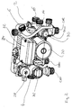
- FIG. 2 shows a Overall perspective view of the assembly according to the invention.
- the pump 20 Centrally located is the pump 20.
- the 2/3-way valve 22 On one side of the pump 20, in Figure 2 left, the 2/3-way valve 22 is arranged, which has a Actuator 28 is actuated.
- a line section with a recording 30 formed for a dirt separator On the opposite side of the pump 20, that is, in Figure 2 right, is a line section with a recording 30 formed for a dirt separator.
- On the bottom of the unit 2 are the connections CHF, CHR, DHW and DCW to the connection of the heating circuit or the water pipes to the Compact heating system designed.
- a terminal box 32 Centrally above the pump 20 is a terminal box 32 for connection of the pump and for receiving arranged by electronic components.
- the structural unit includes all line sections or components of the fluid circuits between the externally connected primary heat exchanger 8 and the connections CHF, CHR, DHW and DCW for the space heating circuit and the service water supply.
- the connections 14 and 16 for a water reservoir for storing heated water of the primary circuit arranged in the receiving housing 30 for the dirt separator.
- the connections 14 and 16 are threaded connections formed integrally with the connection housing 30.
- the entire unit 2 is integrally formed as an injection molded part.
- the assembly of individual housing components be composed.
- the housing part with the receiving housing 30, the housing part for receiving the pump 20 and the housing part for receiving the 2/3-way valve as separate components be manufactured by injection molding and then to the assembly 2 are assembled.
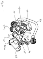
- FIG. 3 shows a perspective view of the part of the assembly 2, in FIG which the receiving housing 30 is formed for the dirt separator is.
- the connection CHR forms the Return of the space heating circuit, through which the water of the Primary circuit, which is heated by the radiator in the Spaces is flowed, arranged in the housing 30 Dirt separator is supplied.
- the DCW connection is used for the supply line to be heated hot water to the secondary heat exchanger 24.
- the secondary heat exchanger 24 is at the openings 34th and 36, wherein the opening 34 via a line section directly connected to the DCW connection to be heated To supply service water to the secondary heat exchanger 24.
- the opening 36 is connected to the primary circuit of the secondary heat exchanger 24th connected and forms the reflux for that from the secondary heat exchanger escaping water of the primary circuit.
- a connecting piece 38 is formed, which with the Suction side of the pump 20 is connected.
- a filling line 40 is provided which via valves the service water pipe between the opening 34 and the DCW connection with connects to the primary heating circuit near the CHR connector.
- the ports 14 and 16 for the water reservoir 18 are adjacent lying in the receiving housing 30, which a line section of the primary circuit forms arranged.
- the terminals 14 and 16 are as a threaded connection piece integral with the housing 30 formed. If no water tank is to be connected, can terminals 14 and 16 via plugs or screw caps be closed.
- the housing 30 in the injection molding so be formed, that in the openings 14 and 16 shorter cores be inserted so that in the connecting piece in the area of the openings 14 and 16 housing walls are formed and the Openings 14 and 16 are closed. So one and the same work train be used to construct a unit 2 for use with a Water storage 18 and also a unit for use without To create water storage 18. If necessary, in the walls be provided in the openings 14 and 16 predetermined breaking points, to be able to open these easily to connect a water tank 18.
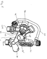
- FIG. 4 is a partially cutaway perspective view of FIG Figure 3 shown receiving housing 30.
- the receiving housing 30th is formed by a formed at the front opening 42 of the Dirt separator 43 used.
- the opening 42 is at the front closed by a closure 44 such that the opening 42 for Removal and replacement of the Schmutzabscheiders 43 open can be.
- the dirt separator 43 is behind in the primary circuit the CHR connector so that the input to the CHR connector Water through the dirt separator 43 to the spigot 38 and on to the suction side of the pump 20 is passed. Further is through the opening 42 in the interior of the receiving housing 32nd a partition 46 used.
- the partition 46 is angled Partition plate, preferably formed of metal.
- the cross to the Circumferential walls of the receiving housing 30 extending portion 48 of the partition member 46 has on its outer periphery a Outer contour corresponding to the inner contour of the receiving housing 30, so that it is close to the inner wall of the receiving housing 30 is present. Also, the extending transversely to the portion 48 area of the separating element 46 lies with its peripheral edges on the Inner walls of the receiving housing 30 sealingly. To this The separating element 46 separates a section at the rear upper End of the receiving housing 30 from the remaining volume of the receiving housing 30, so that inside the receiving housing 30 a second flow channel between the opening 36 and the terminal 16 is formed, which of the remaining area of the receiving housing 30 is disconnected.
- FIG. 5 shows a further sectional view of the receiving housing 30 according to FIGS. 3 and 4.
- FIG. 5 shows how the separating element 46 the interior of the receiving housing 30 in two flow paths divides by abutting the inner circumference of the receiving housing 30.
- the flow path between CHR port and spigot 38 extends in the lower region of the receiving housing 30 below of the separating element 46.
- the separating element 46 is through the opening 42nd inserted from the front into the receiving housing 30 or pressed so that it is kept sealed against the inner wall. there no 100% tightness must be guaranteed, as the Separator 46 only two parts of the primary circuit inside the Unit 2 separates each other and minor leaks the function do not interfere.
- FIG. 6 shows a longitudinal section through the receiving housing 30 according to FIG Figures 3 to 5.
- the separator 46 is used, so that an upper flow channel 50 in this example between the opening 36 and the terminal 16 (not shown here), as well as a lower one Flow channel 52 between the connection CHR and the connecting piece 38 is formed.
- the opening 36 is via an opening 54 in the wall of the receiving housing 30 with the flow channel 50th or the interior of the receiving housing 30 connected.
- the Closure 44 for closing the opening 42 of the receiving housing 30 is also the pressure relief valve of the heating system in the example shown integrated.
Landscapes
- Engineering & Computer Science (AREA)
- Physics & Mathematics (AREA)
- Thermal Sciences (AREA)
- Chemical & Material Sciences (AREA)
- Combustion & Propulsion (AREA)
- Mechanical Engineering (AREA)
- General Engineering & Computer Science (AREA)
- Steam Or Hot-Water Central Heating Systems (AREA)
- Heat-Pump Type And Storage Water Heaters (AREA)
Abstract
Description
- Fig. 1
- schematisch den Aufbau einer Kompaktheizungsanlage mit der erfindungsgemäßen Baueinheit,
- Fig. 2
- eine perspektivische Gesamteinsicht einer bevorzugten Ausführungsform der erfindungsgemäßen Baueinheit,
- Fig. 3
- eine perspektivische Ansicht eines Bauteils der erfindungsgemäßen Baueinheit gemäß Fig. 2 mit den Anschlüssen für den Wärmespeicher,
- Fig. 4
- eine teilweise geschnittenen Ansicht des Bauteils gemäß Fig. 3,
- Fig. 5
- eine teilweise geschnittene Ansicht des Bauteils gemäß Fig. 3 und 4, und
- Fig. 6
- einen Längsschnitt des Bauteils gemäß Fig. 3 bis 5.
- 2
- Baueinheit
- 4
- Anschluss
- 6
- Anschluss
- 8
- Primärwärmetauscher
- 10
- Brenner
- 12
- Anschluss für Ausgleichsgefäß
- 14
- Anschluss für Wasserspeicher
- 16
- Anschluss für Wasserspeicher
- 18
- Wasserspeicher
- 20
- Pumpe
- 22
- 2/3-Wege-Ventil
- 24
- Sekundärwärmetauscher
- 26
- Strömungssensor
- 28
- Stellmotor
- 30
- Aufnahmegehäuse
- 32
- Klemmenkasten
- 34
- Öffnung
- 36
- Öffnung
- 38
- Anschlussstutzen
- 40
- Füllleitung
- 42
- Öffnung
- 43
- Schmutzabscheider
- 44
- Verschluss
- 46
- Trennelement
- 48
- Abschnitt des Trennelementes
- 50
- Strömungskanal
- 52
- Strömungskanal
- 54
- Durchbruch
Claims (10)
- Baueinheit (2) für eine Kompaktheizungsanlage, insbesondere für eine Gastherme, mit zwei Heizkreisen, einem für die Raumheizung und einem für die Brauchwassererwärmung, wobei in der Baueinheit (2) zumindest ein Leitungsabschnitt (30) eines Primärkreislaufes und zumindest eine Pumpe (20) zur Umwälzung des Primärkreislaufes vorhanden sind,
dadurch gekennzeichnet, dass an der Baueinheit (2) in dem zumindest einen Leitungsabschnitt (30) des Primärkreislaufes Anschlüsse (14, 16) für einen Wasserspeicher (18) zum Speichern erwärmten Heizungswassers vorgesehen sind. - Baueinheit nach Anspruch 1, dadurch gekennzeichnet, dass die Anschlüsse (14, 16)für den Wasserspeicher (18) in dem Primärkreislauf in Strömungsrichtung hinter einem Primärwärmetauscher (8) angeordnet sind.
- Baueinheit nach Anspruch 1 oder 2, dadurch gekennzeichnet, dass die Anschlüsse (14, 16) für den Wasserspeicher (18) in dem Primärkreislauf in Strömungsrichtung vor einem Sekundärwärmetauscher (24) zur Erwärmung des Brauchwassers angeordnet ist.
- Baueinheit nach einem der vorangehenden Ansprüche, dadurch gekennzeichnet, dass die Anschlüsse (14, 16) für den Wasserspeicher (18) verschließbar oder geschlossen ausgebildet sind.
- Baueinheit nach einem der vorangehenden Ansprüche, dadurch gekennzeichnet, dass die Anschlüsse (14, 16) für den Wasserspeicher (18) in einem zur Aufnahme eines Schmutzabscheiders (43) ausgebildeten Leitungsabschnitt (30) angeordnet sind.
- Baueinheit nach einem der vorangehenden Ansprüche, dadurch gekennzeichnet, dass im Inneren des Leitungsabschnittes (30) zwischen den Anschlüssen (14, 16) für den Wasserspeicher (18) ein Sperrelement zum Verschließen des Leitungsabschnittes (30) einsetzbar oder eingesetzt ist.
- Baueinheit nach Ansprüchen 5 und 6, dadurch gekennzeichnet, dass der Leitungsabschnitt (30) eine Öffnung (42) zum Einsetzen des Schmutzabscheiders (43) aufweist und das Sperrelement (46) zum Verschließen des Leitungsabschnittes (30) durch diese Öffnung in den Leitungsabschnitt (30) einsetzbar oder eingesetzt ist.
- Baueinheit nach Anspruch 6 oder 7, dadurch gekennzeichnet, dass Sperrelement (46) als Trennwand, vorzugsweise aus Metall, ausgebildet ist, welche in den Leitungsabschnitt (30) eingepresst ist.
- Baueinheit nach einem der vorangehenden Ansprüche, dadurch gekennzeichnet, dass die Anschlüsse (14, 16) für den Wasserspeicher (18) nebeneinander liegend in dem Leitungsabschnitt (30) angeordnet sind.
- Baueinheit nach einem der vorangehenden Ansprüche, dadurch gekennzeichnet, dass die Anschlüsse (14, 16) für den Wasserspeicher (18) im Primärkreislauf an der Saugseite der Pumpe (20) angeordnet sind.
Priority Applications (3)
| Application Number | Priority Date | Filing Date | Title |
|---|---|---|---|
| EP07023409A EP1909041A1 (de) | 2003-11-03 | 2003-11-03 | Baueinheit für eine Kompaktheizungsanlage |
| AT03025081T ATE555349T1 (de) | 2003-11-03 | 2003-11-03 | Baueinheit für eine kompaktheizungsanlage |
| EP03025081A EP1528328B1 (de) | 2003-11-03 | 2003-11-03 | Baueinheit für eine Kompaktheizungsanlage |
Applications Claiming Priority (1)
| Application Number | Priority Date | Filing Date | Title |
|---|---|---|---|
| EP03025081A EP1528328B1 (de) | 2003-11-03 | 2003-11-03 | Baueinheit für eine Kompaktheizungsanlage |
Related Child Applications (2)
| Application Number | Title | Priority Date | Filing Date |
|---|---|---|---|
| EP07023409A Division EP1909041A1 (de) | 2003-11-03 | 2003-11-03 | Baueinheit für eine Kompaktheizungsanlage |
| EP07023409.1 Division-Into | 2007-12-04 |
Publications (2)
| Publication Number | Publication Date |
|---|---|
| EP1528328A1 true EP1528328A1 (de) | 2005-05-04 |
| EP1528328B1 EP1528328B1 (de) | 2012-04-25 |
Family
ID=34400509
Family Applications (2)
| Application Number | Title | Priority Date | Filing Date |
|---|---|---|---|
| EP07023409A Withdrawn EP1909041A1 (de) | 2003-11-03 | 2003-11-03 | Baueinheit für eine Kompaktheizungsanlage |
| EP03025081A Expired - Lifetime EP1528328B1 (de) | 2003-11-03 | 2003-11-03 | Baueinheit für eine Kompaktheizungsanlage |
Family Applications Before (1)
| Application Number | Title | Priority Date | Filing Date |
|---|---|---|---|
| EP07023409A Withdrawn EP1909041A1 (de) | 2003-11-03 | 2003-11-03 | Baueinheit für eine Kompaktheizungsanlage |
Country Status (2)
| Country | Link |
|---|---|
| EP (2) | EP1909041A1 (de) |
| AT (1) | ATE555349T1 (de) |
Cited By (2)
| Publication number | Priority date | Publication date | Assignee | Title |
|---|---|---|---|---|
| FR2894015A1 (fr) * | 2005-11-30 | 2007-06-01 | Muller Et Cie Sa | Embase de chaudiere |
| ITBO20090757A1 (it) * | 2009-11-20 | 2011-05-21 | O T M A S N C Di Spaggiari & C | Gruppo collettore monoblocco multifunzionale per caldaie murali |
Citations (3)
| Publication number | Priority date | Publication date | Assignee | Title |
|---|---|---|---|---|
| GB2262593A (en) * | 1991-12-17 | 1993-06-23 | Inter Albion Ltd | An apparatus for and method of providing hot sanitary water |
| EP0635682A1 (de) * | 1993-07-20 | 1995-01-25 | INTEGRA S.r.l. | Kombi-Kessel mit Wärmespeicherung |
| EP0784191A2 (de) * | 1996-01-15 | 1997-07-16 | Robert Bosch Gmbh | Einrichtung zum Erhitzen von umlaufendem Heizungswasser und Brauchwasser |
Family Cites Families (3)
| Publication number | Priority date | Publication date | Assignee | Title |
|---|---|---|---|---|
| DE19751515C2 (de) * | 1997-11-21 | 1999-12-02 | Grundfos A S Bjerringbro | Baueinheit für eine Kompaktheizungsanlage |
| DE10007873C1 (de) * | 2000-02-21 | 2001-06-28 | Grundfos As | Baueinheit für eine Kompaktheizungsanlage |
| EP1418387B1 (de) * | 2002-11-08 | 2016-01-13 | Grundfos A/S | Kompaktheizungsanlage mit zwei Heizkreisen |
-
2003
- 2003-11-03 EP EP07023409A patent/EP1909041A1/de not_active Withdrawn
- 2003-11-03 AT AT03025081T patent/ATE555349T1/de active
- 2003-11-03 EP EP03025081A patent/EP1528328B1/de not_active Expired - Lifetime
Patent Citations (3)
| Publication number | Priority date | Publication date | Assignee | Title |
|---|---|---|---|---|
| GB2262593A (en) * | 1991-12-17 | 1993-06-23 | Inter Albion Ltd | An apparatus for and method of providing hot sanitary water |
| EP0635682A1 (de) * | 1993-07-20 | 1995-01-25 | INTEGRA S.r.l. | Kombi-Kessel mit Wärmespeicherung |
| EP0784191A2 (de) * | 1996-01-15 | 1997-07-16 | Robert Bosch Gmbh | Einrichtung zum Erhitzen von umlaufendem Heizungswasser und Brauchwasser |
Cited By (3)
| Publication number | Priority date | Publication date | Assignee | Title |
|---|---|---|---|---|
| FR2894015A1 (fr) * | 2005-11-30 | 2007-06-01 | Muller Et Cie Sa | Embase de chaudiere |
| WO2007063252A1 (fr) * | 2005-11-30 | 2007-06-07 | Société Muller & Cie | Embase de chaudière |
| ITBO20090757A1 (it) * | 2009-11-20 | 2011-05-21 | O T M A S N C Di Spaggiari & C | Gruppo collettore monoblocco multifunzionale per caldaie murali |
Also Published As
| Publication number | Publication date |
|---|---|
| EP1909041A1 (de) | 2008-04-09 |
| ATE555349T1 (de) | 2012-05-15 |
| EP1528328B1 (de) | 2012-04-25 |
Similar Documents
| Publication | Publication Date | Title |
|---|---|---|
| EP2312224B1 (de) | Wärmepumpe mit einem Hydraulikmodul | |
| EP2397777B1 (de) | Gehäuseeinheit für eine Heizungsanlage | |
| EP1528330A1 (de) | Baueinheit für eine Kompaktheizungsanlage | |
| EP1130342B2 (de) | Baueinheit für eine Kompaktheizungsanlage | |
| EP0920596A1 (de) | Monolithischer wärmespeicherschrank | |
| EP1528329B1 (de) | Baueinheit für eine Kompaktheizungsanlage | |
| EP1418387B1 (de) | Kompaktheizungsanlage mit zwei Heizkreisen | |
| EP2863131B1 (de) | Warmwasserverteilersystem und Verteilerventil | |
| EP1884720B1 (de) | Baueinheit für eine Kompaktheizungsanlage | |
| EP4382814A1 (de) | Strömungseinrichtung zum nachrüsten einer heizungsanlage und eine heizungsanlage | |
| DE2641601B2 (de) | Wasserspeichererhitzer | |
| EP1528328B1 (de) | Baueinheit für eine Kompaktheizungsanlage | |
| EP3914872B1 (de) | Wärmetauschermodul, wärmetauschersystem und verfahren zum herstellen des wärmetauschersystems | |
| EP2295888B1 (de) | Wassererwärmer | |
| EP1884717B1 (de) | Heizungsanlage | |
| EP4242531B1 (de) | Frostschutzvorrichtung für wasserversorgungsvorrichtung in freizeitfahrzeugen | |
| EP1884723B1 (de) | Baueinheit | |
| EP1528371A1 (de) | Baueinheit für eine Kompaktheizungsanlage | |
| EP2479510A2 (de) | Ventilgarnitur sowie Heizkörper mit einer solchen | |
| DE10102022A1 (de) | Wasserheizanlage | |
| EP2589893A2 (de) | Fluidverteiler | |
| AT413149B (de) | Verteilermodul | |
| DE102008031424B4 (de) | Wärmetauscher | |
| WO2025003335A1 (de) | Heizkreis-hydraulikmodul für ein zentralheizungssystem, abzweigs-strömungskreis-hydraulikmodul für ein zentralheizungssystem, universal-gehäuse für in zentralheizungssysteme einsetzbare hydraulikmodule und zugehöriges zentralheizungssystem | |
| DE19910829B4 (de) | Mehrkreiswärmetauscher |
Legal Events
| Date | Code | Title | Description |
|---|---|---|---|
| PUAI | Public reference made under article 153(3) epc to a published international application that has entered the european phase |
Free format text: ORIGINAL CODE: 0009012 |
|
| 17P | Request for examination filed |
Effective date: 20040827 |
|
| AK | Designated contracting states |
Kind code of ref document: A1 Designated state(s): AT BE BG CH CY CZ DE DK EE ES FI FR GB GR HU IE IT LI LU MC NL PT RO SE SI SK TR |
|
| AX | Request for extension of the european patent |
Extension state: AL LT LV MK |
|
| AKX | Designation fees paid |
Designated state(s): AT BE BG CH CY CZ DE DK EE ES FI FR GB GR HU IE IT LI LU MC NL PT RO SE SI SK TR |
|
| GRAP | Despatch of communication of intention to grant a patent |
Free format text: ORIGINAL CODE: EPIDOSNIGR1 |
|
| GRAJ | Information related to disapproval of communication of intention to grant by the applicant or resumption of examination proceedings by the epo deleted |
Free format text: ORIGINAL CODE: EPIDOSDIGR1 |
|
| GRAP | Despatch of communication of intention to grant a patent |
Free format text: ORIGINAL CODE: EPIDOSNIGR1 |
|
| GRAS | Grant fee paid |
Free format text: ORIGINAL CODE: EPIDOSNIGR3 |
|
| GRAA | (expected) grant |
Free format text: ORIGINAL CODE: 0009210 |
|
| AK | Designated contracting states |
Kind code of ref document: B1 Designated state(s): AT BE BG CH CY CZ DE DK EE ES FI FR GB GR HU IE IT LI LU MC NL PT RO SE SI SK TR |
|
| REG | Reference to a national code |
Ref country code: GB Ref legal event code: FG4D Free format text: NOT ENGLISH |
|
| REG | Reference to a national code |
Ref country code: CH Ref legal event code: EP |
|
| REG | Reference to a national code |
Ref country code: AT Ref legal event code: REF Ref document number: 555349 Country of ref document: AT Kind code of ref document: T Effective date: 20120515 |
|
| REG | Reference to a national code |
Ref country code: IE Ref legal event code: FG4D Free format text: LANGUAGE OF EP DOCUMENT: GERMAN |
|
| REG | Reference to a national code |
Ref country code: DE Ref legal event code: R096 Ref document number: 50314314 Country of ref document: DE Effective date: 20120621 |
|
| REG | Reference to a national code |
Ref country code: NL Ref legal event code: VDEP Effective date: 20120425 |
|
| PG25 | Lapsed in a contracting state [announced via postgrant information from national office to epo] |
Ref country code: FI Free format text: LAPSE BECAUSE OF FAILURE TO SUBMIT A TRANSLATION OF THE DESCRIPTION OR TO PAY THE FEE WITHIN THE PRESCRIBED TIME-LIMIT Effective date: 20120425 Ref country code: SE Free format text: LAPSE BECAUSE OF FAILURE TO SUBMIT A TRANSLATION OF THE DESCRIPTION OR TO PAY THE FEE WITHIN THE PRESCRIBED TIME-LIMIT Effective date: 20120425 Ref country code: CY Free format text: LAPSE BECAUSE OF FAILURE TO SUBMIT A TRANSLATION OF THE DESCRIPTION OR TO PAY THE FEE WITHIN THE PRESCRIBED TIME-LIMIT Effective date: 20120425 |
|
| PG25 | Lapsed in a contracting state [announced via postgrant information from national office to epo] |
Ref country code: SI Free format text: LAPSE BECAUSE OF FAILURE TO SUBMIT A TRANSLATION OF THE DESCRIPTION OR TO PAY THE FEE WITHIN THE PRESCRIBED TIME-LIMIT Effective date: 20120425 Ref country code: GR Free format text: LAPSE BECAUSE OF FAILURE TO SUBMIT A TRANSLATION OF THE DESCRIPTION OR TO PAY THE FEE WITHIN THE PRESCRIBED TIME-LIMIT Effective date: 20120726 Ref country code: PT Free format text: LAPSE BECAUSE OF FAILURE TO SUBMIT A TRANSLATION OF THE DESCRIPTION OR TO PAY THE FEE WITHIN THE PRESCRIBED TIME-LIMIT Effective date: 20120827 |
|
| PG25 | Lapsed in a contracting state [announced via postgrant information from national office to epo] |
Ref country code: RO Free format text: LAPSE BECAUSE OF FAILURE TO SUBMIT A TRANSLATION OF THE DESCRIPTION OR TO PAY THE FEE WITHIN THE PRESCRIBED TIME-LIMIT Effective date: 20120425 Ref country code: EE Free format text: LAPSE BECAUSE OF FAILURE TO SUBMIT A TRANSLATION OF THE DESCRIPTION OR TO PAY THE FEE WITHIN THE PRESCRIBED TIME-LIMIT Effective date: 20120425 Ref country code: NL Free format text: LAPSE BECAUSE OF FAILURE TO SUBMIT A TRANSLATION OF THE DESCRIPTION OR TO PAY THE FEE WITHIN THE PRESCRIBED TIME-LIMIT Effective date: 20120425 Ref country code: DK Free format text: LAPSE BECAUSE OF FAILURE TO SUBMIT A TRANSLATION OF THE DESCRIPTION OR TO PAY THE FEE WITHIN THE PRESCRIBED TIME-LIMIT Effective date: 20120425 Ref country code: CZ Free format text: LAPSE BECAUSE OF FAILURE TO SUBMIT A TRANSLATION OF THE DESCRIPTION OR TO PAY THE FEE WITHIN THE PRESCRIBED TIME-LIMIT Effective date: 20120425 Ref country code: SK Free format text: LAPSE BECAUSE OF FAILURE TO SUBMIT A TRANSLATION OF THE DESCRIPTION OR TO PAY THE FEE WITHIN THE PRESCRIBED TIME-LIMIT Effective date: 20120425 |
|
| PLBE | No opposition filed within time limit |
Free format text: ORIGINAL CODE: 0009261 |
|
| STAA | Information on the status of an ep patent application or granted ep patent |
Free format text: STATUS: NO OPPOSITION FILED WITHIN TIME LIMIT |
|
| 26N | No opposition filed |
Effective date: 20130128 |
|
| REG | Reference to a national code |
Ref country code: DE Ref legal event code: R097 Ref document number: 50314314 Country of ref document: DE Effective date: 20130128 |
|
| BERE | Be: lapsed |
Owner name: GRUNDFOS A/S Effective date: 20121130 |
|
| REG | Reference to a national code |
Ref country code: CH Ref legal event code: PL |
|
| PG25 | Lapsed in a contracting state [announced via postgrant information from national office to epo] |
Ref country code: CH Free format text: LAPSE BECAUSE OF NON-PAYMENT OF DUE FEES Effective date: 20121130 Ref country code: BG Free format text: LAPSE BECAUSE OF FAILURE TO SUBMIT A TRANSLATION OF THE DESCRIPTION OR TO PAY THE FEE WITHIN THE PRESCRIBED TIME-LIMIT Effective date: 20120725 Ref country code: LI Free format text: LAPSE BECAUSE OF NON-PAYMENT OF DUE FEES Effective date: 20121130 |
|
| REG | Reference to a national code |
Ref country code: IE Ref legal event code: MM4A |
|
| PG25 | Lapsed in a contracting state [announced via postgrant information from national office to epo] |
Ref country code: BE Free format text: LAPSE BECAUSE OF NON-PAYMENT OF DUE FEES Effective date: 20121130 |
|
| PG25 | Lapsed in a contracting state [announced via postgrant information from national office to epo] |
Ref country code: IE Free format text: LAPSE BECAUSE OF NON-PAYMENT OF DUE FEES Effective date: 20121103 Ref country code: ES Free format text: LAPSE BECAUSE OF FAILURE TO SUBMIT A TRANSLATION OF THE DESCRIPTION OR TO PAY THE FEE WITHIN THE PRESCRIBED TIME-LIMIT Effective date: 20120805 |
|
| REG | Reference to a national code |
Ref country code: AT Ref legal event code: MM01 Ref document number: 555349 Country of ref document: AT Kind code of ref document: T Effective date: 20121130 |
|
| PG25 | Lapsed in a contracting state [announced via postgrant information from national office to epo] |
Ref country code: AT Free format text: LAPSE BECAUSE OF NON-PAYMENT OF DUE FEES Effective date: 20121130 |
|
| PG25 | Lapsed in a contracting state [announced via postgrant information from national office to epo] |
Ref country code: MC Free format text: LAPSE BECAUSE OF NON-PAYMENT OF DUE FEES Effective date: 20121130 Ref country code: TR Free format text: LAPSE BECAUSE OF FAILURE TO SUBMIT A TRANSLATION OF THE DESCRIPTION OR TO PAY THE FEE WITHIN THE PRESCRIBED TIME-LIMIT Effective date: 20120425 |
|
| PG25 | Lapsed in a contracting state [announced via postgrant information from national office to epo] |
Ref country code: LU Free format text: LAPSE BECAUSE OF NON-PAYMENT OF DUE FEES Effective date: 20121103 |
|
| PG25 | Lapsed in a contracting state [announced via postgrant information from national office to epo] |
Ref country code: HU Free format text: LAPSE BECAUSE OF FAILURE TO SUBMIT A TRANSLATION OF THE DESCRIPTION OR TO PAY THE FEE WITHIN THE PRESCRIBED TIME-LIMIT Effective date: 20031103 |
|
| REG | Reference to a national code |
Ref country code: FR Ref legal event code: PLFP Year of fee payment: 14 |
|
| REG | Reference to a national code |
Ref country code: FR Ref legal event code: PLFP Year of fee payment: 15 |
|
| PGFP | Annual fee paid to national office [announced via postgrant information from national office to epo] |
Ref country code: FR Payment date: 20211119 Year of fee payment: 19 Ref country code: GB Payment date: 20211123 Year of fee payment: 19 Ref country code: DE Payment date: 20211123 Year of fee payment: 19 |
|
| PGFP | Annual fee paid to national office [announced via postgrant information from national office to epo] |
Ref country code: IT Payment date: 20211130 Year of fee payment: 19 |
|
| REG | Reference to a national code |
Ref country code: DE Ref legal event code: R119 Ref document number: 50314314 Country of ref document: DE |
|
| GBPC | Gb: european patent ceased through non-payment of renewal fee |
Effective date: 20221103 |
|
| PG25 | Lapsed in a contracting state [announced via postgrant information from national office to epo] |
Ref country code: IT Free format text: LAPSE BECAUSE OF NON-PAYMENT OF DUE FEES Effective date: 20221103 Ref country code: GB Free format text: LAPSE BECAUSE OF NON-PAYMENT OF DUE FEES Effective date: 20221103 Ref country code: DE Free format text: LAPSE BECAUSE OF NON-PAYMENT OF DUE FEES Effective date: 20230601 |
|
| PG25 | Lapsed in a contracting state [announced via postgrant information from national office to epo] |
Ref country code: FR Free format text: LAPSE BECAUSE OF NON-PAYMENT OF DUE FEES Effective date: 20221130 |