EP1528316B1 - Dispositif de commande de combustion pour bruleur tubulaire et procede de commande de la combustion - Google Patents
Dispositif de commande de combustion pour bruleur tubulaire et procede de commande de la combustion Download PDFInfo
- Publication number
- EP1528316B1 EP1528316B1 EP03795212.4A EP03795212A EP1528316B1 EP 1528316 B1 EP1528316 B1 EP 1528316B1 EP 03795212 A EP03795212 A EP 03795212A EP 1528316 B1 EP1528316 B1 EP 1528316B1
- Authority
- EP
- European Patent Office
- Prior art keywords
- gas
- nozzles
- combustion
- oxygen
- spraying
- Prior art date
- Legal status (The legal status is an assumption and is not a legal conclusion. Google has not performed a legal analysis and makes no representation as to the accuracy of the status listed.)
- Expired - Lifetime
Links
Images


Classifications
-
- F—MECHANICAL ENGINEERING; LIGHTING; HEATING; WEAPONS; BLASTING
- F23—COMBUSTION APPARATUS; COMBUSTION PROCESSES
- F23D—BURNERS
- F23D14/00—Burners for combustion of a gas, e.g. of a gas stored under pressure as a liquid
- F23D14/20—Non-premix gas burners, i.e. in which gaseous fuel is mixed with combustion air on arrival at the combustion zone
- F23D14/22—Non-premix gas burners, i.e. in which gaseous fuel is mixed with combustion air on arrival at the combustion zone with separate air and gas feed ducts, e.g. with ducts running parallel or crossing each other
- F23D14/24—Non-premix gas burners, i.e. in which gaseous fuel is mixed with combustion air on arrival at the combustion zone with separate air and gas feed ducts, e.g. with ducts running parallel or crossing each other at least one of the fluids being submitted to a swirling motion
-
- F—MECHANICAL ENGINEERING; LIGHTING; HEATING; WEAPONS; BLASTING
- F23—COMBUSTION APPARATUS; COMBUSTION PROCESSES
- F23C—METHODS OR APPARATUS FOR COMBUSTION USING FLUID FUEL OR SOLID FUEL SUSPENDED IN A CARRIER GAS OR AIR
- F23C5/00—Disposition of burners with respect to the combustion chamber or to one another; Mounting of burners in combustion apparatus
- F23C5/08—Disposition of burners
- F23C5/32—Disposition of burners to obtain rotating flames, i.e. flames moving helically or spirally
-
- F—MECHANICAL ENGINEERING; LIGHTING; HEATING; WEAPONS; BLASTING
- F23—COMBUSTION APPARATUS; COMBUSTION PROCESSES
- F23C—METHODS OR APPARATUS FOR COMBUSTION USING FLUID FUEL OR SOLID FUEL SUSPENDED IN A CARRIER GAS OR AIR
- F23C3/00—Combustion apparatus characterised by the shape of the combustion chamber
- F23C3/002—Combustion apparatus characterised by the shape of the combustion chamber the chamber having an elongated tubular form, e.g. for a radiant tube
-
- F—MECHANICAL ENGINEERING; LIGHTING; HEATING; WEAPONS; BLASTING
- F23—COMBUSTION APPARATUS; COMBUSTION PROCESSES
- F23C—METHODS OR APPARATUS FOR COMBUSTION USING FLUID FUEL OR SOLID FUEL SUSPENDED IN A CARRIER GAS OR AIR
- F23C3/00—Combustion apparatus characterised by the shape of the combustion chamber
- F23C3/006—Combustion apparatus characterised by the shape of the combustion chamber the chamber being arranged for cyclonic combustion
-
- F—MECHANICAL ENGINEERING; LIGHTING; HEATING; WEAPONS; BLASTING
- F23—COMBUSTION APPARATUS; COMBUSTION PROCESSES
- F23D—BURNERS
- F23D14/00—Burners for combustion of a gas, e.g. of a gas stored under pressure as a liquid
- F23D14/02—Premix gas burners, i.e. in which gaseous fuel is mixed with combustion air upstream of the combustion zone
-
- F—MECHANICAL ENGINEERING; LIGHTING; HEATING; WEAPONS; BLASTING
- F23—COMBUSTION APPARATUS; COMBUSTION PROCESSES
- F23N—REGULATING OR CONTROLLING COMBUSTION
- F23N1/00—Regulating fuel supply
- F23N1/02—Regulating fuel supply conjointly with air supply
- F23N1/022—Regulating fuel supply conjointly with air supply using electronic means
Definitions
- the present invention relates to a combustion controller for a burner included in a furnace or a combustion chamber.
- the present invention also relates to a method for controlling combustion by a tubular flame burner.
- an industrial-use gas burner such as a configuration whose flame is formed in front of the tip of a burner.
- fuel supplied through a fuel-passage and combustion air supplied through an air-passage are sprayed in front of the burner from the nozzle, resulting in forming the turbulence by the sprayed air and fuel.
- nozzle is designed to exhibit the optimal nozzle-flow-velocity so that stable combustion is obtained, which corresponds to the particular heating value and combustion speed of the employed fuel from the thermal perspective and the perspective of fluid dynamics.
- combustion reaction is always performed within a flame that has a certain volume, so the reaction is required to continue for a long period.
- NOx or soot is apt to generate by the reason of the long combustion time.
- the flame has a partial high-temperature region and a low-temperature region, wherein NOx is easy to generate in the high-temperature region, and soot is easy to generate in the low-temperature region.
- a tubular flame burner is disclosed in Japanese Unexamined Patent Application Publication No. 11-281015 .
- This publication includes a tubular combustion chamber of which one-end opens and a nozzle for spraying a fuel gas and a nozzle for spraying an oxygen-containing-gas in the neighborhood of the closed end thereof.
- the nozzle is located, facing in the tangential direction of the inner circumferential wall of the aforementioned combustion chamber.
- the tubular flame burner With the aforementioned tubular flame burner, stable flame is formed in a high-speed swirl within the burner, accordingly combustion is performed with small irregularities in the temperature of a combustion flame. Therefore, no partial high-temperature regions are easy to be formed. Furthermore, stable combustion is achieved even with a low oxygen ratio or air excess ratio. Consequently, the tubular flame burner has the advantage to reduce harmful substances such as NOx or the like, unburned portions of hydrocarbon or the like, and environmental pollutants such as soot and the like, as well as to reduce of the size thereof.
- FIG.8 is explanatory diagrams which show an conventional tubular flame burner, wherein FIG.8A is a configuration diagram which shows the tubular flame burner, and FIG.8B is a cross-sectional view taken along line B-B in FIG.8A .
- the tubular flame burner includes a tubular combustion chamber 121, whose one end opens for serving as an exhaust vent for an exhaust gas. Furthermore, the tubular flame burner includes long slits on the other end along the tube axis, each of which are connected to one of nozzles 122 for separately supplying a fuel gas and a nozzle for supplying an oxygen-containing-gas.
- the nozzles 122 are disposed in a tangential direction of the inner wall of the combustion chamber 121 for spraying the fuel gas and the oxygen-containing-gas so as to form a swirl thereof within the combustion chamber 121. Furthermore, the tip of each nozzle 122 is formed flat with a reduced orifice for spraying the fuel gas and the oxygen-containing-gas at high speed. Note that reference numeral 123 denotes a spark plug.
- the gas within the combustion chamber 121 is stratified into concentric gas layers with different densities, due to difference in the density of the gas and the centrifugal force. That is to say, a high-temperature and low-density exhaust gas exists close to the axis of the combustion chamber 121, and a high-density unburned gas exists close to the inner wall of the combustion chamber 121 (away from the axis thereof). This state exhibits remarkable stability from the viewpoint of fluid dynamics.
- a tube-shaped flame is formed, and the gas flow is stratified into stable layers, thereby forming a film-shaped stable flame.
- the position of the flame is determined, being influenced by the position, wherein two factors (one is the exhaust gas speed toward the center of the combustion chamber 121 and the other is the flame propagation speed) balance each other in natural process.
- reference numeral 124 denotes a tube-shaped flame.
- an unburned low-temperature gas forms a boundary layer near the inner wall of the combustion chamber. Accordingly, the wall of the combustion chamber 121 is not heated by the direct heat transfer to a degree of a high temperature, resulting in avoiding the thermal loss, which means, preventing the heat from releasing to the outside of the wall. That is to say, the aforementioned burner has the effective advantage on great thermal insulation, thereby maintaining thermal stability of combustion.
- the gas within the combustion chamber 121 flows downstream while swirling, and at the same time, the mixture gas around the inner wall continuously burns so as to form a tubular flame. And, a generated exhaust gas flows toward the axis of the combustion chamber 121 so as to be discharged from the open-end.
- the aforementioned tubular flame burner has the same difficult problem on igniting by the electronic spark due to the limited range of the air excess ratio of the fuel gas and the oxygen-containing-gas suitable for the ignition. Accordingly, it may be a case, the aforementioned tubular flame burner requires a pilot burner.
- the conventional tubular flame burner has such problems as the following description.
- the conventional tubular flame burner has a configuration, wherein, in order to form a tubular flame, the respective supply nozzles that are flat along the tube axis are connected to the slits extending along the tube axis. (The slits are located in the tubular combustion chamber.)
- the conventional tubular flame burner is used while spraying the fuel gas and the oxygen-containing-gas into the combustion chamber, simultaneously with forming high-speed swirl of the sprayed fuel gas and the oxygen-containing-gas. Accordingly, the conventional tubular flame burner causes such a problem that relatively high pressure loss happens at the slits. That is to say, in general, the fuel gas and the oxygen-containing-gas are supplied with a constant pressure.
- the problem is as follows.
- the flow speed of the fuel gas and the oxygen-containing-gas is out of the range of the suitable flow speed.
- the suitable flow speed is determined between the flame formation minimal flow speed required for formation of a tube-shaped flame and the permissive maximal flow speed dependent upon the pressure loss, inviting difficulty in stable combustion in a wide range of the combustion load, and resulting in a narrow range of the combustion load suitable for the conventional tubular flame burner.
- the present invention has been conceived in order to solve the aforementioned problems of the conventional tubular flame burner. And the present invention has been conceived and studied in order to provide a combustion controller for a tubular flame burner having a new flame formation mechanism and a corresponding control method, wherein various kinds of fuel may be used, wherein combustion is performed in a wide combustion range, and wherein stable combustion is maintained even with a wide range of the change in combustion load. And in the present invention, stable combustion can be performed, and discharge of an environmental pollution substance created due to combustion is prevented.
- JP H11 21015 A discloses that one end of a tubular combustion room is opened and becomes the exhaust port of a combustion exhaust gas. And, a long slit along the direction of a pipe shaft is formed at the other end part.
- a nozzle for blowing a premixed air consisting of a combustion gas and a gas containing oxygen is provided while being connected to the slit.
- the nozzle is arranged toward the tangential direction of the inner wall surface of the combustion room, and a turning flow is formed in the combustion room due to the blowing of the premixed air.
- the nozzle has a flat tip part and a reduced opening area, so that the premixed air can be blown speedily. Since stable flame is formed in a high-speed turning flow, high-load combustion is enabled and also the adjustment range of the amount of combustion is wide, thus miniaturizing a combustion facility.
- US 3,969,069 A discloses burners of an oven which are operated to satisfy heat loads changeable between a high load and substantially smaller loads. At least under the smaller loads the burners are cyclically controlled in a cycle of time periods T-1 and T-2. During the periods T-1 he burners area steadily regulated to maintain a uniform temperature in the oven. For periods T-2 the burners are periodically controlled to admit one of two selected magnitudes of fuel flow to the oven. At least under the smallest loads the latter magnitudes are periodically controlled to be zero or close to zero.
- US 3,098,883 discloses a process for the pyrolysis of aliphatic. hydrocarbons by continuously forming a stream of hot combustion gas in a combustion zone, wherein said combustion gas is contacted for a short time with, an atomized aliphatic hydrocarbon for pyrolysis thereof to yield C2- to C4-unsaturated hydrocarbons having less hydrogen in the molecule, than the starting material, and, chilling the effluent mixture -of pyrolyzed hydrocarbon and combustion gas, the improvement which comprises introducing into the combustion zone an excess of atomized fuel and an oxidizing gas therefor separately and with an oppositely directed angular momentum at a different distance from the axis of said combustion zone to form rotating coaxially arranged hollow atmospheres of different diameter which contrarotate in one another.
- a combustion controller according to the present invention is alternatively defined by the combination of features of claim 1 or of claim 2.
- a method for controlling combustion of a tubular flame burner according to the present invention is alternatively defined by the combination of features of claim 4 or of claim 5.
- Dependent claims relate to referred embodiments.
- tubular flame burner which may be used together with the controller and/or the method are described.
- a tubular flame burner may comprise:
- a tubular flame burner may comprise:
- a tubular flame burner may comprise:
- a tubular flame burner may comprise:
- a combustion controller for a tubular flame burner may comprise :
- a combustion controller for a tubular flame burner may comprise:
- a combustion controller for a tubular flame burner may comprise:
- a combustion controller for a tubular flame burner may comprise:
- a combustion control method for a tubular flame burner may comprise:
- a method for controlling a combustion by a tubular flame burner may comprise:
- a method for controlling combustion by a tubular flame burner may comprise:
- a method for controlling combustion by a tubular flame burner may comprise:
- a method for controlling combustion by a tubular flame burner may comprise:
- a method for controlling combustion by a tubular flame burner may comprise:
- FIG.1 through FIG.3 show a first embodiment.
- FIG.1 is a side view of a tubular flame burner according to the present embodiment
- FIG.2 is a cross-sectional view taken along line A-A in FIG.1 .
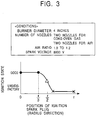
- FIG.3 is an explanatory diagram for describing ignition of the tubular burner according to the present embodiment.
- reference numeral 10 denotes a tubular combustion chamber, wherein the front-end 10a opens so as to serve as an exhaust vent for an exhaust gas. Furthermore, the tubular combustion chamber 10 includes nozzles near the rear-end 10b thereof for spraying fuel gas and oxygen- containing-gas into the tubular combustion chamber 10. Furthermore, the tubular combustion chamber 10 includes an ignition spark plug 21 on the rear-end 10b thereof for generating a spark within the combustion chamber 10 using an igniter 22 and a power supply 23.
- slits 12 are formed along the tube axis on the circumferential of the tubular combustion chamber 10, serving as nozzles for the combustion chamber 10, wherein the slits 12 are connected to nozzles 11a, 11b, 11c, and 11d, formed flat and long and narrow along the tube axis, respectively.
- These nozzles 11a, 11b, 11c, and 11d are disposed so that each spray direction is in a tangential direction of the inner circumferential wall of the combustion chamber 10 so as to form a swirl in a predetermined direction.
- the nozzles 11a and 11c serve as fuel-gas spraying nozzles
- the nozzles 11b and 11d serve as oxygen-containing-gas spraying nozzles.
- the fuel-gas spraying nozzles 11a and 11c spray the fuel gas toward the tangential direction of the inner circumferential wall of the combustion chamber 10 at a high speed
- the oxygen-containing-gas spraying nozzles 11b and 11d spray the oxygen-containing-gas toward the tangential direction of the inner circumferential wall of the combustion chamber 10 at a high speed, so as to form a swirl while efficiently mixing the fuel gas and the oxygen-containing-gas at a region near the inner circumferential wall of the combustion chamber 10.
- the mixture gas forming such a swirl is suitably ignited by the ignition spark plug 21 so as to form a tube-shaped flame within the combustion chamber 10.
- a combustion gas is discharged from the front-end 10a of the combustion chamber 10a.
- oxygen-containing-gas represents a gas for carrying oxygen used for combustion such as air, oxygen, oxygen-enriched air, exhaust mixture gas, or the like.
- the ignition spark plug 21 is disposed at a position between the tube axis of the combustion chamber 10 and a position away therefrom by r/2 (note that r denotes the radius of the combustion chamber).
- FIG.3 shows the relation between the mounting position of the ignition spark plug 21 along the radius direction of the combustion chamber 10 and the ignition state using the ignition spark plug 21. This illustrates that the combustion chamber 10 including the ignition spark plug 21 at a position between the tube axis and the position away therefrom by r/2 exhibits excellent ignition.
- tubular flame burner according to the present embodiment does not require any pilot burner for ignition, thereby reducing the size and costs thereof.
- the tubular flame burner has a configuration, that is, a reduced distance L between each of the nozzles 11a through lid and the rear-end 10b of the combustion chamber 10, in order to further reduce the size thereof, the distance L is insufficient for mixing the fuel gas and the oxygen-containing-gas. Because, it leads to a problem that the region where gas fuel and oxygen-containing fuel are mixed in a suitable range of the air excess ratio may be reduced in the radius direction near the rear-end 10b of the combustion chamber 10. Accordingly, the ignition spark plug 21 is preferably disposed at a position between the tube axis and the position away therefrom by r/3. Thus, even in case of the tubular flame burner having such a configuration wherein the nozzles 11a through lid are disposed close to the ignition spark plug 21 (L ⁇ 0), excellent ignition can be done in a definite way to be stable.
- the ignition spark plug is disposed at a suitable position near the tube axis of the combustion chamber, thereby performing ignition of a mixture gas of the fuel gas and the oxygen-containing-gas within the combustion camber in a definite way to be stable.
- the tubular flame burner according to the present embodiment requires no ignition pilot burner, thereby reducing the size and costs thereof.
- tubular flame burner according to the present embodiment may be also formed with a polygonal cross-sectional shape rather than round.
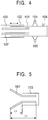
- FIG. 4 is a longitudinal cross-sectional diagram, which shows a tubular flame burner according to the present embodiment.
- the tubular flame burner comprises a combustion chamber 103 formed of an inner tube 101 of which one end opens, and an outer tube 102 wherein both ends opens, and which can be slid along the outer circumferential wall of the inner tube 101, a fuel-spraying nozzle 104 and an oxygen-containing-gas-spraying nozzle 105, wherein a nozzle orifice of each is formed on the inner face of the inner tube 101 of the aforementioned combustion chamber 103.
- the fuel-spraying nozzle 104 and the oxygen-containing-gas-spraying nozzle 105 are connected so that each spraying direction generally matches the tangential direction of the inner circumferential wall of the combustion chamber 103 as viewed in the diameter direction of the combustion chamber 103.
- the oxygen-containing-gas represents a gas for carrying oxygen used for combustion such as air, oxygen, oxygen-enriched air, exhaust mixture gas, or the like.
- the fuel is sprayed from the fuel-spraying nozzle 104 into the combustion chamber 103 as well as spraying the oxygen-containing-gas from the oxygen-containing-gas-spraying nozzle 105, and ignition is made by the ignition plug 106, whereby a tube-shaped flame is formed along the inner circumferential wall of the inner tube 101 of the combustion chamber 103.
- the flame thus formed is referred to as a tube-shaped flame 107.
- a tubular flame burner is designed so that combustion of the tube-shaped flame 107 is made within the combustion chamber 103, with this tubular flame burner, a part of the tube- shaped flame 107 can be formed on the outside of the inner tube 101, wherein in the event that the outer tube 102 is slid so as to extend the combustion chamber 103, the entire tube-shaped flame 107 is formed within the combustion chamber 103. And on the other hand, in the event that the outer tube 102 is slid so as to collapse the combustion chamber 103, a part of the tube-shaped flame 107 is formed on the outside of the combustion camber 103.
- the lengths of the inner tube 101 and the outer tube 102 may be experimentally determined as well as being theoretically determined. With the entire length of the tube-shaped flame 107 thus formed as L 1 , and with the length of the tube-shaped flame 107 formed on the outside of the combustion chamber 103 as L 2 , as shown in FIG.5 , the greater the value L 2 /L 1 is, the greater the heat transfer amount and the amount of created soot are, as shown in the chart in FIG.6 . The reason why is that the increased L 2 causes an increase of the ratio of a luminous flame, and accordingly, the ratio of stable combustion is reduced within the combustion chamber 103 as well as promoting heat transfer to the heated object. This results in such a state that soot is readily generated.
- the reason why is that increased ratio of combustion on the outside of the combustion chamber 103 within the furnace space leads to dilution-combustion while swirling an exhaust gas within a space on the outside of the combustion chamber 103. Accordingly, the concentration of oxygen is reduced within the combustion space as well as preventing generation of partial high-temperature region, thereby suppressing reaction of creation of thermal NOx, and thereby suppressing the amount of created NOx.
- the tubular flame burner controls the heat transfer amount, the amount of created soot, and the amount of the created NOx.
- tubular flame burner according to the present embodiment may be also formed with a polygonal cross-sectional shape rather than round.
- Combustion testing was performed using the described tubular flame burner.
- FIG.9 is a chart that shows the in-furnace temperature (curve A) and the temperature of steel (curve B) over time, which have been measured in the combustion test.
- the in-furnace temperature is raised at a constant temperature increase rate to 1000°C, and upon reaching 1000°C, the temperature is maintained at 1000°C for a total heating time of 15 hours.
- FIG.10 shows concentration of NOx and soot over time obtained in the aforementioned combustion test.
- an index representation of the concentration thereof is expressed with the permissive value as 100.
- the measured temperature of the steel after heating for 15 hours was 950°C, which was considerably lower than the determined temperature of 1000°C.
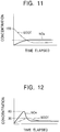
- FIG.11 shows the concentration of NOx and soot over time obtained in the aforementioned combustion test.
- an index representation of the concentration is made with the permissive values as 100.
- the amount of the generated soot became small after the in-furnace temperature reached 1000°C, which brings up a little bit problem.
- the amount of the generated NOx was suppressed to a low level over all the heating steps. That is to say, the combustion in such a case causes no problems to generate NOx, while leading to a small problem of a somewhat great amount of the soot generated in the temperature-rising step.
- the measured temperature of the steel after heating for 15 hours was 980°C, which was closer to the determined temperature of 1000°C, compared with the first combustion test. It has been revealed that the second combustion method exhibits more efficient heating of steel than with the first combustion method, except for generating the soot at a low temperature.
- FIG.12 shows concentration of NOx and soot over time obtained in the aforementioned combustion test.
- an index representation of the concentration thereof is made with the permissive values as 100 in the same way.
- both the amount of the generated soot and that of the generated NOx exists in a stable condition, resulting in suppressing the concentration values to low levels.
- the amount of the generated soot is suppressed to an extent of the concentration value, 30 or less.
- the amount of the generated NOx is suppressed to an extent of the concentration value, 80 or less over all the heating steps, whereby excellent heating is achieved.
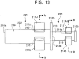
- FIG.13 through FIG. 16 show a multi-stage tubular flame burner.
- FIG.13 is a side view of the multi-stage tubular flame burner according to the present embodiment.
- FIG.14A is a cross-sectional view taken line A-A in FIG.13 .
- FIG.14B is a cross-sectional view taken line B-B in FIG. 13 .
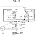
- FIG.15 and FIG.16 are explanatory diagrams, which describes a method for controlling combustion by the multi-stage tubular flame burner according to the present embodiment.
- reference numeral 201 denotes the multi-stage tubular flame burner according to the present embodiment.
- FIG.13 has such a configuration that a small-diameter flame burner 213 with a small inner diameter is connected to the rear-end of a large-diameter flame burner 202 with a large inner diameter in series, so as to form a single tubular flame burner.
- the large-diameter tubular flame burner 202 includes a tubular combustion chamber 210, whose one end 210a opens for serving as an exhaust vent for a combustion gas, and nozzles 211a, 211b, 211c, and 211d, for separately spraying a fuel gas and an oxygen-containing-gas into the combustion chamber 210.
- Long and narrow slits 212 are formed at the four parts.
- the four parts are located on the same single circumference of the combustion chamber 210, and these slits are located at the neighborhood of the rear-end 210b of the combustion chamber 210, in order to serve them as nozzle orifices for the combustion chamber 210.
- these slits 212 are connected to nozzles 211a, 211b, 211c, and 211d, as being formed flat, being long and narrow along the tube axis, respectively.
- the nozzles 211a, 211b, 211c, and 211d are disposed so that the spraying direction of each is in a tangential direction of the inner circumferential wall of the combustion chamber 210, so as to cause a swirl in a single rotational direction.
- two nozzles of the nozzles 211a and 211c serve as fuel-gas-spraying nozzles
- the rested two nozzles of these four nozzles, 211b and 211d serve as oxygen-containing-gas-spraying nozzles.
- the fuel-gas-spraying nozzles 211a and 211c spray a fuel gas in the tangential direction of the inner circumferential wall of the combustion chamber 210 at a high speed, as well as the oxygen-containing-gas-spraying nozzles 211b and 211d spraying an oxygen-containing-gas in the tangential direction of the inner circumferential wall of the combustion chamber 210 at a high speed, so as to form a swirl while efficiently mixing the fuel gas and the oxygen-containing-gas at a region near the inner circumferential wall of the combustion chamber 210.
- an ignition device such as an ignition plug, pilot burner, or the like
- a tube-shaped flame is formed within the combustion chamber 210.
- a combustion gas is discharged from the front-end 210a of the combustion chamber 210.
- the small-diameter tubular flame burner 203 includes a tubular combustion chamber 213 having a configuration.
- the front-end 213a is connected to the rear-end 210b of the large-diameter tubular flame burner 202, so as to serve as an exhaust vent for a combustion gas, and nozzles 214a, 214b, 214c, and 214d, for separately spraying a fuel gas and an oxygen-containing-gas into the combustion chamber 213.
- Long and narrow slits 215 are formed at the respective four parts, on the same single circumference of the combustion chamber 213.
- these slits 215 are connected to nozzles 214a, 214b, 214c, and 214d, as being flat, long and narrow along the tube axis, respectively.
- the respective nozzles 214a, 214b, 214c, and 214d, are disposed so that the spraying direction of each is in a tangential direction of the inner circumferential wall of the combustion chamber 213, so as to cause a swirl in a single rotational direction.
- two nozzles, 214a and 214c serve as fuel-gas-spraying nozzles
- the rested two nozzles of these nozzles, 214b and 214d serve as oxygen-containing-gas-spraying nozzles.
- the slits 212 of the large-diameter tubular flame burner 202 are formed with the area of each orifice larger than the slits 215 of the small-diameter tubular flame burner 203 corresponding to a larger inner diameter of the combustion chamber 210 of the large-diameter tubular flame burner 202.
- the fuel-gas-spraying nozzles 214a and 214c spray a fuel gas in the tangential direction of the inner circumferential wall of the combustion chamber 213 at a high speed, as well as the oxygen-containing-gas-spraying nozzles 214b and 214d spraying an oxygen-containing-gas in the tangential direction of the inner circumferential wall of the combustion chamber 213 at a high speed, so as to form a swirl while efficiently mixing the fuel gas and the oxygen-containing-gas at a region near the inner circumferential wall of the combustion chamber 213.
- an ignition device such as an ignition plug, pilot burner, or the like
- a tube-shaped flame is formed within the combustion chamber 213.
- a combustion gas is discharged from the front-end 210a through the front-end 213a of the combustion chamber 213 and the combustion chamber 210 of the large-diameter tubular flame burner 202.
- oxygen-containing-gas represents a gas for carrying oxygen used for combustion such as air, oxygen, oxygen-enriched air, exhaust mixture gas, or the like.
- an switching valve 216a for switching supply of the fuel gas to the nozzles 211a and 211c is disposed at a portion on a line for supplying the fuel gas to the fuel-gas-spraying nozzles 211a and 211c of the large-diameter tubular flame burner 202
- an switching valve 216b for switching supply of the oxygen-containing-gas to the nozzles 211b and 211d is disposed at a portion on a line for supplying the oxygen-containing-gas to the fuel-gas-spraying nozzles 211b and 211d of the large-diameter tubular flame burner 202.
- an switching valve 217a for switching supply of the fuel gas to the nozzles 214a and 214c is disposed at a portion on a line for supplying the fuel gas to the fuel-gas-spraying nozzles 214a and 214c of the small-diameter tubular flame burner 203
- an switching valve 217b for switching supply of the oxygen-containing-gas to the nozzles 214b and 214d is disposed at a portion on a line for supplying the oxygen-containing-gas to the fuel-gas-spraying nozzles 214b and 214d of the large-diameter tubular flame burner 203.
- a supply controller 220 is provided for controlling on/off of the switching valves 216a, 216b, 217a, and 217b, whereby the tubular flame burner to be used is selected for use by the on/off control thereof.
- a fuel-gas-flow regulator 218 for adjusting the total flow of the fuel gas to be supplied to the fuel-gas-spraying nozzles 211a, 211c, 214a, and 214c, is disposed on a line for supplying the fuel gas
- an oxygen-containing-gas-flow regulator 219 for adjusting the total flow of the oxygen-containing-gas to be supplied to the oxygen-containing-gas-spraying nozzles 211b, 211d, 214b, and 214d, is disposed on a line for supplying the oxygen-containing-gas.
- the supply controller 220 controls the fuel-gas-flow regulator 218 and the oxygen-containing-gas-flow regulator 219 so as to control the total flow of supplied fuel gas and oxygen-containing-gas.
- the total supply flow of the fuel gas and the oxygen-containing-gas is measured by a flow-meter 221 for the fuel gas and a flow-meter 222 for the oxygen-containing-gas, and the measurement value is sent to the supply controller 220 so as to be used for adjusting the apertures of the fuel-gas-flow regulator 218 and the oxygen-containing-gas-flow regulator 219.
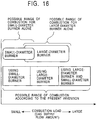
- a desired tubular flame burner is selected for combustion from the large-diameter tubular flame burner 202 and the small-diameter tubular flame burner 203 corresponding to the combustion load.
- each of the large-diameter tubular flame burner 202 and the small-diameter tubular flame burner 203 has a particular possible range of combustion. That is, a particular range of the combustion load, corresponding to the range of supply flow between the minimal flame-formation flow speed required for forming a tubular flame and the maximal permissive flow speed dependent upon the pressure loss.
- the small-diameter tubular flame burner 203 is formed with a small inner diameter of the combustion chamber and a small aperture area of the slits.
- the large-diameter tubular flame burner 202 is formed with a large inner diameter of the combustion chamber and a large aperture area of the slits, and accordingly has a possible range of combustion corresponding to a range of a relatively large combustion load.
- the small-diameter tubular flame burner 203 is used. And in the event that the combustion load becomes greater, the large-diameter tubular flame burner 202 is used. And in the event that the combustion load becomes much greater, both the large-diameter tubular flame burner 202 and the small-diameter tubular flame burner 203 are used.
- the multi-stage tubular flame burner according to the present embodiment enables stable combustion to be in a wide range of the combustion load, which is difficult for a single-diameter tubular flame burner.
- tubular flame burner according to the present embodiment may also be formed with a polygonal cross-sectional shape, rather than round.
- the multi-stage tubular flame burner has a configuration for adjusting the total flow of the fuel gas and the total flow of the oxygen-containing-gas to be supplied to the tubular flame burner that has a large diameter, and/or the tubular flame burner that has a small-diameter.
- An arrangement according to the present embodiment has a configuration for further adjusting the total flow of the fuel gas and the total flow of the oxygen-containing-gas to be supplied for each of the large-diameter tubular flame burner 210 and the small-diameter tubular flame burner 213.
- a fuel-gas-flow regulator 218a for adjusting the flow of the fuel gas to be supplied to the fuel-gas-spraying nozzles 211a and 211c is provided on a line for supplying the fuel gas to the tubular flame burner 210 that has a large-diameter
- an oxygen-containing-gas-flow regulator 219a for adjusting the flow of the oxygen-containing-gas to be supplied to the oxygen-containing-gas-spraying nozzles 211b and 211d is provided on a line for supplying the oxygen-containing-gas to the tubular flame burner that has a large-diameter 210.
- the supply controller 220a adjusts the fuel-gas-flow regulator 218a and the oxygen-gas-flow regulator 219a, so as to control each of the fuel-gas flow and the oxygen-containing-gas flow to be supplied to the large-diameter tubular flame burner.
- the supply flow of the fuel gas and the supply flow of the oxygen-containing-gas are measured by a fuel-gas flow-meter 221a and an oxygen-containing-gas flow-meter 222a, respectively. And the measurement values are sent to the supply controller 220a, so as to be used for aperture adjustment of the fuel-gas-flow regulator 218a and the oxygen-containing-gas-flow regulator 219a.
- a fuel-gas-flow regulator 218b for adjusting the flow of the fuel gas to be supplied to the fuel-gas-spraying nozzles 214a and 214c is provided on a line for supplying the fuel gas to the small-diameter tubular flame burner 213.
- an oxygen-containing-gas-flow regulator 219b for adjusting the flow of the oxygen-containing-gas to be supplied to the oxygen-containing-gas-spraying nozzles 214b and 214d is provided on a line for supplying the oxygen-containing-gas to the small-diameter tubular flame burner 213.
- the supply controller 220b adjusts the fuel-gas-flow regulator 218b and the oxygen-gas-flow regulator 219b, so as to control each of the fuel-gas flow and the oxygen-containing-gas flow to be supplied to the small-diameter tubular flame burner 213.
- the supply flow of the fuel gas and the supply flow of the oxygen-containing-gas are measured by a fuel-gas flow-meter 221b and an oxygen-containing-gas flow-meter 222b, respectively. And the measurement values are sent to the supply controller 220b so as to be used for aperture adjustment of the fuel-gas-flow regulator 218b and the oxygen-containing-gas-flow regulator 219b.
- the supply controller 220a for the large-diameter tubular flame burner 210 and the supply controller b for the small-diameter tubular flame burner 213 are interconnected each other for adjusting the total supply flow of the fuel gas and the oxygen-containing-gas.
- each of the apertures are adjusted corresponding to the combustion state.
- each of the apertures exists between the fuel-gas-flow regulator 218b and the oxygen-containing-gas-flow regulator 219b of the tubular flame burner 213 that has the small diameter.
- each of the apertures is determined and adjusted to be zero, wherein the respective apertures exist between the fuel-gas-flow regulator 218a and the oxygen-containing-gas-flow regulator 219a of the tubular flame burner 210 that has a large-diameter.
- each of the apertures of the fuel-gas-flow regulator 218a and the oxygen-containing-gas-flow regulator 219a of the large-diameter tubular flame burner 210 are adjusted corresponding to the combustion state.
- each of the apertures of the fuel-gas-flow regulator 218b is set to be zero, wherein each of the apertures exist between the oxygen-containing-gas-flow regulator 219b of the small-diameter tubular flame burner 213.
- the fuel-gas-flow regulator 219b of the large-diameter tubular flame burner 210 opens corresponding to the combustion load. And concerning the apertures of the fuel-gas-flow regulator 218a and the oxygen-containing-gas-flow regulator 219a of the large-diameter tubular flame burner 210 and the apertures of the fuel-gas-flow regulator 218b and the oxygen-containing-gas-flow regulator 219b of the small-diameter tubular flame burner 213, they are as follows. That is, both of the apertures are adjusted respectively, corresponding to the combustion load.
- the multi-stage tubular flame burner according to the present embodiment enables stable combustion to exist within a wide range of the combustion load, which is hard to be applied to a single-diameter tubular flame burner.
- each slit serving as the nozzles for the combustion chamber are disposed along the tube axis, and wherein each slit is connected to the corresponding flat fuel-gas spraying nozzle or oxygen-containing spraying nozzle.
- an arrangement is applied to that multiple small-sized openings, which serve as a nozzle orifice for the combustion chamber, are formed along the tube axis.
- each nozzle is connected to the corresponding array formed of the small-sized openings for spraying the fuel gas or the oxygen-containing-gas.
- a suitable tubular flame burner is used selectively for combustion corresponding to the variable increasing/decreasing combustion load, resulting in making it possible to keep a stable combustion in_accordance with a wide range of the combustion load.
- the tubular flame burner according to the present embodiment may also be formed with a polygonal cross-sectional shape, rather than round.
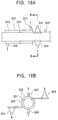
- FIG.18A is a configuration diagram of the tubular flame burner
- FIG. 18B is a view taken along line B-B in FIG. 18A .
- the tubular flame burner includes a tubular combustion chamber 301 whose one-end opens and nozzles 304 for spraying a fuel gas and an oxygen-containing-gas.
- each nozzle orifice of the nozzles is formed on the inner face of the aforementioned combustion chamber 301. It is disposed so that each spraying direction is in a neighborhood of a tangential direction of the inner circumferential wall of such a configuration that the combustion chamber 301 is combustion chamber 301.
- the tubular flame burner has covered with an outer tube 302, which has a greater outer diameter than that of the combustion chamber 301. This is as a role to form a space between the outer face of the combustion chamber 301 and the inner face of the outer tube 302.
- the space between the outer face and the inner face serves as a flow path 303 for a fuel gas or an oxygen-containing-gas.
- the path is provided before being supplied to the aforementioned spraying nozzle, as well as forming the combustion chamber 301 with a greater length than that of a tube-shaped flame formed therein.
- One end of the combustion chamber 301 opens for serving as an exhaust vent for a combustion exhaust gas. Furthermore, long slits are formed on the other end of the combustion chamber 301 along the tube axis, and are connected to nozzles 304 for separately spraying the fuel gas and the oxygen-containing-gas.
- the nozzles 304 are disposed in a neighborhood of a tangential direction of the inner circumferential wall of the combustion chamber 301, so as to form a swirl within the combustion chamber 301 due to spraying of the fuel gas and the oxygen-containing-gas. Note that the tip of each nozzle 304 is formed flat with a reduced orifice area so as to spray the fuel gas and the oxygen-containing-gas at a high speed.
- Reference numeral 305 denotes an ignition plug.
- the outer tube 302 has closed front-end and rear-one. And the outer tube has a configuration, wherein a pipe 306 is connected to a portion on the front-end side of the outer tube 302 for supplying a combustion gas or an oxygen-containing-gas to a space 303 formed between the combustion camber 301 and the outer tube 302.
- a pipe 307 connected to one of the aforementioned nozzle 304, is connected to a portion on the rear-end side of the outer tube 302, so as to introduce the preheated fuel gas or oxygen-containing-gas to the nozzle 304.
- the preheated fuel gas is supplied, the oxygen-containing-gas before having been preheated is supplied to the other nozzle 304 that is disposed thereon.
- the preheated oxygen-containing-gas is supplied, the fuel gas before having been preheated is supplied to the other nozzle 304 that is disposed thereon.
- the tubular flame burner has the same configuration as the conventional tubular flame burners, except for the above-described configuration, wherein the fuel gas or the oxygen-containing-gas is preheated, so as to be supplied to the combustion chamber 301.
- the tubular flame burner has the same combustion mechanism as the conventional tubular flame burners. Accordingly, detailed description thereof is omitted.
- the tubular flame burner according to the present embodiment is formed so that the combustion chamber is longer than a tube-shaped flame formed therewithin. Accordingly, while the front-end of the combustion chamber becomes high temperature due to the combustion gas, the fuel gas or oxygen-containing-gas that has a room temperature cools the combustion chamber. Accordingly, the burner is not damaged due to heat, thereby improving the life span of the burner. Furthermore, with the tubular flame burner according to the present embodiment, the fuel gas or oxygen-containing-gas is preheated, thereby improving combustion performance, and thereby extending a range of kinds of fuel, which can be employed for combustion.
- tubular flame burner according to the present embodiment may also be formed with a polygonal cross-sectional shape rather than round.
- combustion test was performed, using fuel that has a low calorific heating value. Note that combustion test was also performed using a conventional single-tube tubular flame burner as a comparative example (without preheating of the combustion air or fuel).
- a mixture gas formed of only a blast furnace gas or formed by mixing the blast furnace gas (BFG) with N 2 gas or a coke-oven gas (COG) is employed as the aforementioned fuel gas that has a lower calorific heating value than that of the blast furnace gas. Table 1 shows the obtained results.
- examples of the fuel gases with low heat output used in the present examples 2 and 3 include an exhaust gas from a reducing atmosphere furnace or a non-oxidizing atmosphere furnace. Such an untreated exhaust gas cannot be discharged prohibited. Therefore, the exhaust gas is burned with a dedicated combustion furnace so as to be discharged into the air. From such a viewpoint, the present embodiment has such an advantage that double-tube tubular flame furnace enables combustion to be made using such an exhaust gas as a fuel gas without requiring a special dedicated combustion furnace.
- FIG.19 through FIG.22 show an embodiment 5-1 according to the present invention.
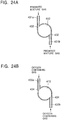
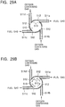
- FIG.19 is a side view of a tubular flame burner according to the present embodiment
- FIG.20A is a cross-sectional view taken along line A-A in FIG.19
- FIG.20B is a cross-sectional view taken along line B-B in FIG. 19 .
- FIG.21 is an overall configuration diagram of a combustion controller for the tubular flame burner according to the present embodiment
- FIG.22 is an explanatory diagram for describing a combustion control method for the tubular flame burner according to the present embodiment.
- reference numeral 410 denotes a tube-shaped combustion chamber, wherein the front-end 410a opens so as to serve as an exhaust vent for a combustion exhaust gas. Furthermore, the combustion chamber 410 includes two nozzle-mounting portions A and B on the side of the rear-end 410b along the tube axis for mounting nozzles for spraying a fuel gas to the combustion chamber 410, and nozzles for spraying an oxygen-containing-gas thereto.
- nozzle-mounting portion A four long and narrow slits 412 extending along the tube axis are formed along the circumferential wall of the combustion chamber 410 so as to serve as nozzles for the combustion chamber 410. And these slits are connected to nozzles 411a, 411b, 411c, and 411d, formed flat, and long and narrow along the tube axis, respectively, as shown in FIG. 19 and FIG. 20A .
- the nozzles 411a, 411b, 411c, and 411d are disposed so that each spraying direction is in a tangential direction of the inner circumferential wall of the combustion chamber 410 so as to cause a swirl to be in a predetermined rotational direction.
- the nozzle 411a and the nozzle 411c serve as fuel-gas-spraying nozzles
- the nozzle 411b and the nozzle 411d serve as oxygen-containing-gas spraying nozzles.
- the fuel gas is sprayed from the fuel-gas spraying nozzles 411a and 411c in the tangential direction of the inner circumferential wall of the combustion chamber 410 at a high speed.
- Such a procedure is as well as spraying the oxygen-containing-gas from the oxygen-containing-gas spraying nozzles 411b and 411d in the tangential direction of the inner circumferential wall of the combustion chamber 410 at a high speed.
- an ignition device such as an ignition plug, pilot burner, or the like, a tube-shaped flame is formed within the combustion chamber 410.
- nozzle-mounting portion B four long and narrow slits 414 extending along the tube axis are formed along the circumferential wall of the combustion chamber 410 so as to serve as nozzles for the combustion chamber 410.
- These nozzles are connected to nozzles 413a, 413b, 413c, and 413d, formed flat, and long and narrow along the tube axis, respectively, as shown in FIG.19 and FIG.20B .
- the nozzles 413a, 413b, 413c, and 413d are disposed so that each spraying direction is in a tangential direction of the inner circumferential wall of the combustion chamber 410 so as to cause a swirl to be in a predetermined rotational direction.
- the nozzle 413a and the nozzle 413c serve as fuel-gas-spraying nozzles
- the nozzle 413b and the nozzle 413d serve as oxygen-containing-gas spraying nozzles.
- the fuel gas is sprayed from the fuel-gas spraying nozzles 413a and 413c in the tangential direction of the inner circumferential wall of the combustion chamber 410 at a high speed.
- This procedure is done as well as spraying the oxygen-containing-gas from the oxygen-containing-gas spraying nozzles 413b and 413d in the tangential direction of the inner circumferential wall of the combustion chamber 410 at a high speed, so as to form a swirl while efficiently mixing the fuel gas and the oxygen-containing-gas at a region near the inner circumferential wall of the combustion chamber 410.
- an ignition device such as an ignition plug, pilot burner, or the like, a tube-shaped flame is formed within the combustion chamber 410.
- the tubular flame burner according to the present embodiment includes two nozzle sets along the tube axis. Each of these ones are formed of two fuel-gas-spraying nozzles and two oxygen-containing-gas spraying nozzles along the circumference of the tube, i.e., the tubular flame burner according to the present embodiment includes four fuel-gas-spraying nozzles and four oxygen-containing-gas spraying nozzles.
- oxygen-containing-gas represents a gas for carrying oxygen used for combustion such as air, oxygen, oxygen-enriched air, exhaust mixture gas, or the like.
- switching valves 415a, 415c, 416a, and 416c for controlling on/off of the fuel gas to the nozzles 411a, 411c, 413a, and 413c, respectively, are disposed on lines for supplying the fuel gas to the fuel-gas spraying nozzles 411a, 411c, 413a, and 413c, respectively.
- And switching valves 415b, 415d, 416b, and 416d, for controlling on/off of the oxygen-containing-gas to the nozzles 411b, 411d, 413b, and 413d, respectively, are disposed on lines for supplying the oxygen-containing-gas to the oxygen-containing-gas spraying nozzles 411b, 411d, 413b, and 413d, respectively.
- a supply controller 420 is provided for controlling on/off of the switching valves 415a, 415b, 415c, 415d, 416a, 416b, 416c, and 416d, so as to select desired nozzles for spraying the fuel gas and the oxygen-containing-gas to the combustion chamber 410.
- the line for supplying the fuel gas includes a fuel-gas-flow regulator 417 for adjusting the total supply flow of the fuel gas to be supplied to the fuel-gas-spraying nozzles 411a, 411c, 413a, and 413c
- the line for supplying the oxygen-containing-gas includes an oxygen-containing-gas-flow regulator 418 for adjusting the total supply flow of the oxygen-containing-gas to be supplied to the oxygen-containing-gas-spraying nozzles 411b, 411d, 413b, and 413d.
- the supply controller 420 adjusts the fuel-gas-flow regulator 417 and the oxygen-containing-gas-flow regulator 418 so as to control each entire flow of the fuel gas and the oxygen-containing-gas to be supplied according to the combustion load. That is to say, in case of small combustion load, the apertures of the fuel-gas-flow regulator 417 and the oxygen-containing-gas-flow regulator 418 are reduced so as to reduce the total supply flow thereof. And on the other hand, in case of a great combustion load, the apertures of the fuel-gas-flow regulator 417 and the oxygen-containing-gas-flow regulator 418 are increased so as to increase the total supply flow thereof.
- a fuel-gas flow-meter 421 and an oxygen-containing-gas flow-meter 422 measure each of total supply flow of the fuel gas and the oxygen-containing-gas. And the measured values are sent to the supply controller 420 so as to be used for adjusting the apertures of the fuel-gas-flow regulator 417 and the oxygen-containing-gas-flow regulator 418.
- the number of nozzles used for spraying the fuel gas and the oxygen-containing-gas to the combustion chamber 410 is determined according to the combustion load so that the fuel gas and the oxygen-containing-gas are sprayed at an initial flow speed in a range between the maximal permissive flow speed Vp dependent upon the pressure loss and the minimal flow speed Vq required for forming a tube-shaped flame.
- the supplied fuel gas flow is divided into two halves so as to be sprayed from the two fuel-gas spraying nozzles 411a and 411c, respectively, and the supplied oxygen-containing-gas flow is divided into two halves so as to be sprayed from the two oxygen-containing-gas spraying nozzles 411b and 411d, respectively.
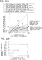
- the initial flow speed from the spraying nozzles relatively gently increase over the increased total supply flow, i.e., increased combustion load, as shown by the line L 2 in FIG.22A .
- the flow speed increases over the combustion load with a half ratio as compared with a case of using a single nozzle 411a for spraying the fuel gas and a single nozzle 411b for spraying the oxygen-containing-gas.
- the flow speed relatively slowly reaches the minimal flow speed Vq required for forming a tube-shaped flame, the flow speed relatively slowly exceeds the maximal permissive flow speed Vp dependent upon the pressure loss.
- the supplied fuel gas flow is divided into four quarters so as to be sprayed from the four fuel-gas spraying nozzles 411a, 411c, 413a, and 413c, respectively, and the supplied oxygen-containing-gas flow is divided into four quarters so as to be sprayed from the four oxygen-containing-gas spraying nozzles 411b, 411d, 413b, and 413d, respectively.
- the initial flow speed from the spraying nozzles extremely gently increases over the increased total supply flow, i.e., the increased combustion load as shown by the line L 3 in FIG.17A .
- the flow speed increases over the combustion load with a quarter ratio as compared with a case of using a single nozzle 411a for spraying the fuel gas and a single nozzle 411b for spraying the oxygen-containing-gas.
- the flow speed considerably slowly reaches the minimal flow speed Vq required for forming a tube-shaped flame, the flow speed considerably slowly exceeds the maximal permissive flow speed Vp dependent upon the pressure loss.
- the present combustion control method determines that the number of the nozzles to be used for spraying the fuel gas and the oxygen-containing-gas is adjusted by the supply controller 420, which controls on/off of the switching valves 415a, 415b, 415c, 415d, 416a, 416b, 416c, and 416d.
- the supply controller 420 controls on/off of the switching valves 415a, 415b, 415c, 415d, 416a, 416b, 416c, and 416d.
- Such a determination is done, in order for the fuel gas and the oxygen-containing-gas to be sprayed into the combustion chamber 410, at an initial flow speed within a range of the maximal permissive flow speed Vp and the minimal flow speed Vq.
- Vp is dependent upon the pressure loss
- Vq is required for forming a tube-shaped flame. Specifically, as shown in FIG.
- a single nozzle for spraying the fuel gas and a single nozzle for spraying the oxygen-containing-gas are used.
- a combustion load is fallen within a range from a approximately 1/4 of the predetermined maximum combustion load to approximately 1/2 of the predetermined maximum combustion load
- two nozzles for spraying the fuel gas and two nozzles for spraying the oxygen-containing-gas are used.
- four nozzles for spraying the fuel gas and four nozzles for spraying the oxygen-containing-gas are used.
- the initial flow speed from the spraying nozzles is obtained within a range between the maximal permissive flow speed Vp (Vp is dependent on the pressure loss), and the minimal flow speed Vq (Vp is required for forming a tube-shaped flame).
- Vp maximal permissive flow speed
- Vq minimal flow speed
- the tubular flame burner according to the present embodiment includes two nozzles that set along the tube axis.
- Each of these nozzles is formed of two fuel-gas-spraying nozzles and two oxygen-containing-gas-spraying nozzles along a single circumference of the tubular combustion chamber 410.
- These nozzles have such a configuration that the nozzles to be used for combustion are selected from the multiple fuel-gas spraying nozzles and the oxygen-containing-gas spraying nozzles.
- These nozzles are used by appropriately controlling on/off of the switching values, so as to exhibit a predetermined flow speed, even in case of change in the total supply flow of the fuel gas and the oxygen-containing-gas, corresponding to change in the combustion load. This results in suppressing the pressure loss at the time of an increase of the supply flow, as well as maintaining formation of a swirl at the time of reduction of the supply flow.
- the tubular flame burner including two nozzle sets along the tube axis, each of which are formed of two fuel-gas spraying nozzles and two oxygen-containing-gas spraying nozzles along a single circumference thereof
- the tubular flame burner may include a suitable number of nozzle sets along the tube axis, each of which are formed of a suitable number of fuel-gas spraying nozzles and two oxygen-containing-gas spraying nozzles along a single circumference thereof, as appropriate.
- the slits serving as the nozzles for the combustion chamber are disposed along the tube axis. And each slit is connected to the corresponding flat fuel-gas spraying nozzle or oxygen-containing spraying nozzle.
- An arrangement may be made, wherein multiple small-sized openings serving as a nozzle orifice for the combustion chamber are formed along the tube axis. And each nozzle is connected to the corresponding array formed of the small-sized openings for spraying the fuel gas or the oxygen-containing-gas.
- tubular flame burner according to the present embodiment may also be formed with a polygonal cross-sectional shape rather than round.
- FIG. 26 is an overall configuration diagram, which shows a combustion controller for a tubular flame burner according to the present embodiment.
- the combustion controller has such a configuration as the total flow of the fuel gas and the total flow of the oxygen-containing-gas. Here, they are supplied to the nozzles at the mounting portion A and/or the nozzles at the mounting portion B are adjusted, as shown in FIG.21 .
- the combustion controller according to the present embodiment has a configuration wherein the fuel-gas flow and the oxygen-containing-gas flow to be supplied to the nozzles mounted on the mounting portion A are independently adjusted.
- the line for supplying the fuel gas to the nozzles at the mounting portion A includes a fuel-gas-flow regulator 417a for controlling the fuel-gas flow to be supplied to the fuel-gas spraying nozzles 411a and 411c.
- the line for supplying the oxygen-containing-gas to the nozzles at the mounting portion A includes an oxygen-containing-gas-flow regulator 418a for controlling the oxygen-containing-gas flow to be supplied to the oxygen-containing-gas spraying nozzles 411b and 411d.
- the fuel-gas-flow regulator 417a and the oxygen-containing-gas-flow regulator 418a are controlled by the supply controller, thereby enabling the fuel gas flow and the oxygen-containing-gas flow to be adjusted in order to be supplied to the nozzles at the mounting portion A.
- the flow-meter 421a for the fuel gas and the flow-meter 422a for the oxygen-containing-gas measure the supply amounts of the fuel gas and the oxygen-containing-gas, respectively. And the measured values are sent to the supply controller 420a so as to be used for adjusting the apertures of the fuel-gas-flow regulator 417a and the oxygen-containing-gas-flow regulator 418a.
- the line for supplying the fuel gas to the nozzles at the mounting portion B includes a fuel-gas-flow regulator 417b for controlling the fuel-gas flow to be supplied to the fuel-gas spraying nozzles 413a and 413c.
- the line for supplying the oxygen-containing-gas to the nozzles at the mounting portion B includes an oxygen-containing-gas-flow regulator 418b for controlling the oxygen-containing-gas flow to be supplied to the oxygen-containing-gas spraying nozzles 413b and 413d.
- the supply controller 420b controls the fuel-gas-flow regulator 417b and the oxygen-containing-gas-flow regulator 418b.
- the supply amounts of the fuel gas and the oxygen-containing-gas to be supplied to the nozzles at the mounting portion B are measured by the flow-meter 421b for the fuel gas, and the flow-meter 422b for the oxygen-containing-gas, respectively.
- the measured values are sent to the supply controller 42.0b so as to be used for adjusting the apertures of the fuel-gas-flow regulator 417b and the oxygen-containing-gas-flow regulator 418b.
- the supply controller 420a for the nozzles at the mounting portion A and the supply controller 420b for the nozzles at the mounting portion B, are interconnected each other for adjusting the total supply flow of the fuel gas and the oxygen-containing-gas.
- switching valves 415a and 415c are provided for controlling on/off of the supply of the fuel gas to the fuel-gas spraying nozzles 411a and 411c at the mounting portion A.
- the line for supplying the oxygen-containing-gas to the oxygen-containing-gas spraying nozzles 411b and 411d at the mounting portion A includes switching valves 415b and 415d for controlling on/off of supply of the oxygen-containing-gas to the nozzles 411b and 411d, respectively.
- each of the switching valves 415a, 415b, 415c, and 415d are controlled by the supply controller 420a.
- the aforementioned line for supplying the fuel gas to the fuel-gas spraying nozzles 413a and 413c at the mounting portion B includes switching valves 416a and 416c for controlling on/off of the supply of the fuel gas to the fuel-gas-spraying nozzles 413a and 413c.
- the line for supplying the oxygen-containing-gas to the oxygen-containing-gas spraying nozzles 413b and 413d at the mounting portion B includes switching valves 416b and 416d for controlling on/off of supply of the oxygen-containing-gas to the nozzles 413b and 413d.
- each of the switching valves 416a, 416b, 416c, and 416d are controlled by the supply controller420b.
- the supply controllers 420a and 420b control on/off of the nozzles, thereby selecting the nozzles to be used for spraying the fuel gas and the oxygen-containing-gas to the combustion chamber 410.
- the number of the nozzles to be used for combustion is suitably selected from the multiple combustion-gas spraying nozzles and oxygen-containing-gas spraying nozzles.
- Controlling on/off of the switching valves does such a way, and this way is as well as adjusting the flow supplied to each nozzle by controlling the corresponding regulator, so as to obtain a predetermined spraying speed. It ends up in suppressing the pressure loss when the supply flow increases, as well as maintaining formation of a swirl when the supply flow reduces. Even in the event of change in the total supply flow of the fuel gas and the oxygen-containing-gas corresponding to change in the combustion load, the above-mentioned procedure is done.
- tubular flame burner according to the present embodiment may also be formed with a polygonal cross-sectional shape rather than round.
- FIG.23 through FIG.25 show an embodiment 5-3 according to the present invention.
- FIG.23 is a side view of a tubular flame burner according to the present embodiment
- FIG.24A is a cross-sectional view taken along line A-A in FIG.23
- FIG.24B is a cross-sectional view taken along line B-B in FIG.23 .
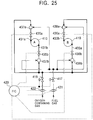
- FIG.25 is an overall configuration diagram, which shows a combustion controller for the tubular flame burner according to the present embodiment.
- reference numeral 410 is a tubular combustion chamber, wherein the one end 410a opens so as to serve as an exhaust vent for combustion exhaust gas. Furthermore, the tubular combustion chamber 410 includes two nozzle-mounting portions A and B along the tube axis on the side of the rear-end 410b thereof for spraying a fuel gas and an oxygen-containing-gas to the combustion chamber 410.
- two long and narrow slits 432 extending along the tube axis are formed along the circumferential wall of the combustion chamber 410, so as to serve as nozzles for the combustion chamber 410. And such slits are connected to nozzles 431a and 431b, formed flat, and long and narrow along the tube axis, respectively, as shown in FIG. 23 and FIG. 24A .
- These nozzles 431a and 431b are disposed so that each spraying direction thereof is in a tangential direction of the inner circumferential wall of the combustion chamber 410 so as to form a swirl in a predetermined direction. Note that a premixed gas wherein the fuel gas and the oxygen-containing-gas have been mixed beforehand is supplied to the nozzles 431a and the nozzles 431b.
- the premixed gas is sprayed in the tangential direction of the circumferential wall of the combustion chamber 410 at a high speed from the premixed-gas spraying nozzles 431a and 431b to which the premixed gas is supplied. This is done so as to form a swirl at a region near the inner circumferential wall of the combustion chamber 410.
- an ignition device such as an ignition plug, pilot burner, or the like, are ignited, a tube-shaped flame is formed within the combustion chamber 410.
- two long and narrow slits 434 extending along the tube axis are formed along the circumferential wall of the combustion chamber 410, so as to serve as nozzles for the combustion chamber 410.
- slits are connected to nozzles 433a and 433b, formed flat, and long and narrow along the tube axis, respectively, as shown in FIG.23 and FIG.24B .
- These nozzles 433a and 433b are disposed so that each spraying direction thereof is in a tangential direction of the inner circumferential wall of the combustion chamber 410 so as to form a swirl in a predetermined direction.
- a premixed gas wherein the fuel gas and the oxygen-containing-gas have been mixed beforehand is supplied to the nozzles 433a and the nozzles 433b.
- the premixed gas is sprayed in the tangential direction of the circumferential wall of the combustion chamber 410 at a high speed from the premixed-gas spraying nozzles 433a and 433b to which the premixed gas is supplied. This is done, so as to form a swirl at a region near the inner circumferential wall of the combustion chamber 410.
- an ignition device such as an ignition plug, pilot burner, or the like
- a tube-shaped flame is formed within the combustion chamber 410.
- the tubular flame burner according to the present embodiment includes two nozzles that set along the tube axis. Each of these nozzles are formed of two premixed-gas spraying nozzles along a single circumference of the combustion chamber, i.e., the tubular flame burner according to the present embodiment includes four premixed-gas spraying nozzles.
- the lines for supplying the premixed gas to the premixed-gas spraying nozzles 431a, 431b, 433a, and 433b include switching valves 435a, 435b, 436a, and 436b, for controlling on/off of the supply of the premixed gas to the nozzles 431a, 431b, 433a, and 433b, respectively.
- the lines further include gas mixers 437a, 437b, 438a, and 438b, for premixing the fuel gas and the oxygen-containing-gas beforehand, respectively.
- the supply controller 420 thereby enabling the nozzles to be selectively used for spraying the premixed gas to the combustion chamber 410, performs on/off control of the switching valves 435a, 435b, 436a, and 436b.
- the line for supplying the fuel gas to the gas mixers 437a, 437b, 438a, and 438b includes a fuel-gas-flow regulator 417 for adjusting the total flow of the fuel gas to be supplied.
- the line for supplying the oxygen-containing-gas to the gas mixers 437a, 437b, 438a, and 438b includes an oxygen-containing-gas-flow regulator 418 for adjusting the total flow of the oxygen-containing-gas to be supplied.
- the fuel-gas-flow regulator 417 and the oxygen-containing-gas-flow regulator 418 are controlled by the supply controller 420 so as to adjust the total flow of the fuel gas and the total flow of the oxygen-containing-gas, which are to be supplied, corresponding to the combustion load.
- the apertures of the fuel-gas-flow regulator 417 and the oxygen-containing-gas-flow regulator 418 reduces, so as to reduce the total supply flow.
- the apertures of the fuel-gas-flow regulator 417 and the oxygen-containing-gas-flow regulator 418 increases so as to increase the total supply flow.
- the flow-meter 421 for the fuel gas and the flow-meter 422 for the oxygen-containing-gas measure each of the total supply flow of the fuel gas and the oxygen-containing-gas. And the measurement results are sent to the supply controller 420, so as to be used for adjusting the apertures of the fuel-gas-flow regulator 417 and the oxygen-containing-gas-flow regulator 418.
- Combustion control with the combustion controller for a tubular flame burner having such a configuration is performed in the same way as with the above-described embodiment.
- the number of the nozzles to be used for spraying the premixed gas is adjusted by the supply controller 420 controlling on/off of the switching valves 435a, 435b, 436a, and 436b, corresponding to the combustion load, so that the initial flow speed of the premixed gas sprayed to the combustion chamber is maintained in a range between the maximal permissive flow speed Vp dependent upon the pressure loss and the minimal flow speed Vq required for forming a tube-shaped flame.
- a single nozzle for spraying the premixed gas is used.
- two nozzles for spraying the premixed gas are used.
- four nozzles for spraying the premixed gas are used.
- the initial flow speed from the spraying nozzles is obtained within a range between the maximal permissive flow speed Vp (dependent upon the pressure loss) and the minimal flow speed Vq(required for forming a tube-shaped flame), thereby suppressing excessive pressure loss while maintaining the high speed of the flow required for forming a tube-shaped flame.
- the tubular flame burner according to the present embodiment includes two nozzles that set along the tube axis. Each of these nozzles is formed of two nozzles for spraying the premixed gas, along a single circumference of the tubular combustion chamber 410.
- the tubular flame burner wherein the number of the nozzles to be used for combustion, is suitably selected from the multiple nozzles for spraying the premixed gas, by controlling on/off of the switching valves so as to exhibit a predetermined flow speed, even in a case of change in the total supply flow of the premixed gas corresponding to change in the combustion load, thereby suppressing the pressure loss at the time of an increase of the supply flow, as well as maintaining formation of a swirl at the time of reduction of the supply flow.
- tubular flame burner including two nozzles that sets along the tube axis. Each of these nozzles is formed of two nozzles for spraying the premixed gas along a single circumference thereof.
- the tubular flame burner may include a suitable number of nozzle sets along the tube axis, each of which are formed of a suitable number of nozzles for spraying the premixed gas along a single circumference thereof, as appropriate.
- the slits serving as the nozzles for the combustion chamber are disposed along the tube axis, and each slit is connected to the corresponding flat nozzle for spraying the premixed gas.
- An arrangement may be made wherein multiple small-sized openings are formed along the tube axis, and each nozzle is connected to the corresponding array formed of the small-sized openings for spraying the premixed gas.
- a gas formed by preheating liquid fuel may be employed as a fuel gas.
- liquid fuel which readily evaporate under relatively low temperature, such as kerosene, gas oil, alcohol, A-type heave oil, or the like, is suitably employed as the liquid fuel.
- tubular flame burner according to the present embodiment may also be formed with a polygonal cross-sectional shape rather than round.
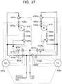
- FIG. 27 is an overall configuration diagram, which shows a combustion controller for a tubular flame burner according to the present embodiment.
- the combustion controller according to the above-described embodiment 5-3 has a configuration.
- the total flow of the fuel gas and the total flow of the oxygen-containing-gas, which are to be supplied to the premixed-gas spraying nozzles at the mounting portion A and/or to the fuel-gas spraying nozzles at the mounting portion B, are adjusted as shown in FIG.25 .
- the combustion controller according to the present embodiment has a configuration wherein the fuel-gas flow and the oxygen-containing-gas flow, which are to be supplied to the premixed-gas spraying nozzles at the mounting portion A, are independently adjusted.
- the line for supplying the fuel gas to the premixed spraying nozzles 431a and 431b at the mounting portion A includes the fuel-gas flow regulator 417a for adjusting the flow of the fuel-gas, which is to be supplied.
- the line for supplying the oxygen-containing-gas to the premixed spraying nozzles 431a and 431b at the mounting portion A includes the oxygen-containing-gas-flow regulator 418a for adjusting the flow of the oxygen-containing-gas, which is to be supplied.
- the fuel-gas-flow regulator 417a and the oxygen-containing-gas-flow regulator 418a are controlled by the supply controller 420a, thereby enabling the fuel-gas flow and the oxygen-containing-gas flow to be adjusted, which are to be supplied to the premixed-gas spraying nozzles 431a and 431b at the mounting portion A.
- the supply flow of the fuel gas and the supply flow of the oxygen-containing-gas are measured by the flow-meter 421a for the fuel gas and the flow-meter 422a for the oxygen-containing-gas, respectively. And the measured results are sent to the supply controller 420a, so as to be used for adjusting the apertures of the fuel-gas-flow regulator 417a and the oxygen-containing-gas-flow regulator 418a.
- the line for supplying the fuel gas to the premixed spraying nozzles 433a and 433b at the mounting portion B includes the fuel-gas-flow regulator 417b for adjusting the flow of the fuel gas which is to be supplied.
- the line for supplying the oxygen-containing-gas to the premixed spraying nozzles 433a and 433b at the mounting portion B includes the oxygen-containing-gas-flow regulator 418b for adjusting the flow of the oxygen-containing-gas, which is to be supplied.
- the supply controller 420b controls the fuel-gas-flow regulator 417b and the oxygen-containing-gas-flow regulator418b.
- Such a controlling method makes it possible to adjust the fuel-gas flow and the oxygen-containing-gas flow, which are to be supplied to the premixed-gas spraying nozzles 433a and 433b at the mounting portion B, and the flow-meter for the oxygen-containing-gas.
- the supply flow of the fuel gas and the supply flow of the oxygen-containing-gas are measured by the flow-meter 421b for the fuel gas and the flow-meter 422b for the oxygen-containing-gas, respectively. And the measured results are sent to the supply controller 420b so as to be used for adjusting the apertures of the fuel-gas-flow regulator 417b and the oxygen-containing-gas-flow regulator 418b.
- the supplv controller 420a for the premixed-gas spraying nozzles431a and 431b at the mounting portion A, and the supply controller 420b for the premixed-gas spraying nozzles 433a and 433b at the mounting portion B, are interconnected each other for adjusting the total supply flow of the fuel gas and the oxygen-containing-gas.
- the line for supplying the premixed gas to the premixed-gas spraying nozzle 431a at the mounting portion A from the gas mixer 437a includes the switching valve 435a for controlling on/off of supply of the premixed gas to the premixed-gas spraying nozzle 431a.
- the line for supplying the premixed gas to the premixed-gas spraying nozzle 431b at the mounting portion A from the gas mixer 437b includes the switching valve 433b for controlling on/off of supply of the premixed gas to the premixed-gas spraying nozzle 431b.
- the line for supplying the premixed gas to the premixed-gas spraying nozzle 433a at the mounting portion B from the gas mixer 438a includes the switching valve 436a for controlling on/off of supply of the premixed gas to the premixed-gas spraying nozzle 433a.
- the line for supplying the premixed gas to the premixed-gas spraying nozzle 433b at the mounting portion B from the gas mixer 438b includes the switching valve 436b for controlling on/off of supply of the premixed gas to the premixed-gas spraying nozzle 433b.
- On/off control of the switching valves 435a and 435b is performed by the supply controller 420a. And on/off control of the switching valves 436a and 436b is performed by the supply controller 420b.
- the nozzles to be used for spraying the premixed gas to the combustion chamber 410 are selected by the aforementioned on/off control.
- the number of the nozzles to be used for combustion is suitably selected from the multiple nozzles for spraying the premixed gas, by controlling on/off of the switching valves. And the flow supplied to each nozzle is adjusted by controlling the corresponding flow regulator, so as to exhibit a predetermined flow speed. This is done, even in a case of change in the total supply flow of the premixed gas corresponding to change in the combustion load. This makes it possible to suppress the pressure loss when an increase of the supply flow increases, as well as maintaining formation of a swirl at the time of reduction of the supply flow.
- the number of the nozzles to be used for spraying the fuel gas and the oxygen-containing-gas to the combustion chamber, or the number of the nozzles to be used for spraying the premixed gas formed of the fuel gas and the oxygen-containing-gas to the combustion chamber is suitably selected so as to exhibit a predetermined spraying speed. This is done, even in case of change in the total supply flow of the fuel and oxygen-containing-gas corresponding to change in the combustion load, thereby achieving stable combustion in a wider range of the combustion load.
- tubular flame burner according to the present embodiment may also be formed with a polygonal cross-sectional shape rather than round.
- FIG. 28 through FIG. 31 show an embodiment 6.
- FIG. 28 is a side view of a tubular flame burner according to the present embodiment
- FIG. 29A is a cross-sectional view taken along line A-A in FIG. 28 .
- FIG. 30 is an overall configuration diagram which shows a combustion controller for the tubular flame burner according to the present embodiment
- FIG. 31 is an explanatory diagram for describing a combustion control method for the tubular flame burner according to the present embodiment.
- reference numeral 510 denotes a tubular combustion chamber, wherein the front-end 510a opens so as to serve as an exhaust vent for a combustion exhaust gas. Furthermore, the combustion chamber 510 includes nozzles for spraying a fuel gas to the combustion chamber 510, and nozzles for spraying an oxygen-containing-gas thereto, near the rear-end 510 thereof.
- the combustion chamber 510 includes four long and narrow slits 512 arrayed along a single tube circumference. Each of these slits are formed long along the tube axis thereof, so as to serve as nozzles for the combustion camber 510, which are connected to nozzles 511a, 511b, 511c, and 511d, formed flat, long and narrow along the tube axis thereof, respectively. These nozzles 511a, 511b, 511c, and 511d, are disposed so that each spraying direction is in a tangential direction of the inner circumferential wall of the combustion chamber 510 so as to form a swirl in a predetermined direction. Of these four nozzles, the nozzles 511a and 511c serve as fuel-gas spraying nozzles, and the nozzles 511b and 511d serve as oxygen-containing-gas spraying nozzles.
- the fuel gas is sprayed in the tangential direction of the inner circumferential wall of the combustion chamber 510 at a high speed from the fuel-gas spraying nozzles 511a and 511c.
- the oxygen-containing-gas is sprayed in the tangential direction of the inner circumferential wall of the combustion chamber 510 at a high speed from the oxygen-containing-gas spraying nozzles 511b and 511d, so as to form a swirl while efficiently mixing the fuel gas and the oxygen-containing-gas at a neighborhood region of the inner circumferential wall of the combustion chamber 510.
- the tubular flame burner When the mixture gas forming a swirl the tubular flame burner is ignited by an ignition device (not shown) such as an ignition plug, pilot burner, or the like, a tube-shaped flame is formed within the combustion chamber 510. A combustion gas therefrom is discharged from the front-end 510a of the combustion chamber 510.
- an ignition device such as an ignition plug, pilot burner, or the like
- oxygen-containing-gas represents a gas for carrying oxygen used for combustion such as air, oxygen, oxygen-enriched air, exhaust mixture gas, or the like.
- a slit aperture adjusting ring 513 is disposed at a portion, where the slits 512 are disposed, so as to be in contact with the inner wall of the combustion chamber 510 for adjusting the apertures of the slits 512.
- the slit aperture-adjusting ring 513 is formed in the shape of a tube with a small thickness.
- the slit aperture includes four slots along the circumferential direction corresponding to the four slits 512, wherein the apertures of the four slits 512 are adjusted by rotating the slit aperture adjusting ring 513 in the direction of the tube circumference.
- FIG.29A shows the combustion chamber 510, wherein the slots of the slit aperture adjusting ring 513 just matches with the corresponding slits 512, so as to adjust the aperture of each slit 512 to the maximum.
- FIG. 29B shows the combustion chamber 510, wherein the slit aperture adjusting ring 513 is rotated by a certain angle from the state shown in FIG. 29A , so that a part of each slit 512 is closed with the slit aperture adjusting ring 513 so as to reduce the aperture of each slit 512.
- the line for supplying the fuel gas includes the fuel-gas-flow regulator 517 for adjusting the flow of the fuel gas to be supplied to the fuel-gas spraying nozzles 511a and 511c
- the line for supplying the oxygen-containing-gas includes the oxygen-containing-gas-flow regulator 518 for adjusting the flow of the oxygen-containing-gas to be supplied to the oxygen-containing-gas spraying nozzles 511b and 511d.
- the supply controller 520 so as to adjust the supply flow of the fuel gas and the oxygen-containing-gas corresponding to the combustion load, controls the fuel-gas-flow regulator 517 and the oxygen-containing-gas-flow regulator 518.
- the apertures of the fuel-gas-flow regulator 517 and the oxygen-containing-gas-flow regulator 518 are reduced, so as to reduce the supply flow thereof.
- the apertures of the fuel-gas-flow regulator 517 and the oxygen-containing-gas-flow regulator 518 are increased so as to increase the supply flow thereof.
- the supply flow of the fuel gas and the supply flow of the oxygen-containing-gas are measured by the flow-meter 521 for the fuel gas and the flow-meter 522 for the oxygen-containing-gas, respectively. And the measurement results are sent to the supply controller 520 so as to be used for adjusting the apertures of the fuel-gas-flow regulator 517 and the oxygen-containing-gas-flow regulator 518.
- a motor 514 is provided for adjusting the angular position of the slit aperture adjusting ring 513, is controlled by the supply controller 520, and adjusts the apertures of the slits 512 by controlling the angular position of the slit aperture adjusting ring 513.
- an actuator such as a hydraulic cylinder, an air cylinder, or the like, may be employed instead of the motor 514.
- the apertures of the slits 512 are adjusted in the following way. That is, the initial flow speed of the fuel gas and the oxygen-containing-gas sprayed to the combustion chamber 510 is maintained within a range from the maximal permissive flow speed Vp (dependent upon the pressure loss) and the minimal flow speed Vq (required for forming a tube-shaped flame).
- the initial flow speed of the flow from the spraying nozzles 511a through 511d exhibits a rapid increase corresponding to the increased supply flow, i.e., the increased combustion load.
- the flow speed rapidly reaches the minimal flow speed Vq (required for forming a tube-shaped flame)
- the flow speed rapidly exceeds the maximal permissive flow speed Vp(dependent upon the pressure loss).
- the initial flow speed of the flow from the spraying nozzles exhibits a relatively gentle increase thereof corresponding to the increased supply flow, i.e., the increased combustion load, as shown by the line L 2 in FIG.31A .
- the flow speed relatively slowly reaches the minimal flow speed Vq (required for forming a tube-shaped flame)
- the flow speed relatively slowly exceeds the maximal permissive flow speed Vp (dependent upon the pressure loss).
- the initial flow speed of the flow from the spraying nozzles exhibits an extremely gentle increase thereof corresponding to the increased supply flow, i.e., the increased combustion load, as shown by the line L3 in FIG. 31A .
- the flow speed considerably slowly reaches the minimal flow speed Vq (required for forming a tube-shaped flame)
- the flow speed considerably slowly exceeds the maximal permissive flow speed Vp (dependent upon the pressure loss).
- the supply controller 520 controls the angular position of the slit aperture adjusting ring 513, so as to adjust the apertures of the slits 512 such that the initial flow speed of the fuel gas.
- the oxygen-containing-gas sprayed to the combustion chamber 510 is maintained in a range between the maximal permissive flow speed Vp (dependent upon the pressure loss) and the minimal flow speed (Vq required for forming a tube-shaped flame based upon the above-described relation).
- the apertures of the slits 512 are reduced. In case of combustion load in a range between approximately 1/3 of the predetermined maximal combustion load to approximately 2/3 thereof, the apertures of the slits 512 somewhat increases. Furthermore, in case of a combustion load in a range between approximately 2/3 of the predetermined maximal combustion load to the predetermined maximal combustion load, the apertures of the slits 512 increases to the maximum, to perform combustion.
- the initial flow speed from the spraying nozzles is maintained within a range from the maximal permissive flow speed Vp (dependent upon the pressure loss) and the minimal flow speed (Vq required for forming a tube-shaped flame), resulting in suppressing excessive pressure loss while maintaining the high speed of the flow required for forming a tube-shaped flame.
- each slit serving as the nozzles for the combustion chamber are disposed along the tube axis
- each slit is connected to the corresponding fuel-gas spraying nozzle or oxygen-containing-gas spraying nozzle.
- the nozzle has been formed flat, an arrangement may be made wherein multiple small-sized openings are formed along the tube axis, and each of the fuel-gas spraying nozzles and the oxygen-containing-gas spraying nozzles are connected to the corresponding array formed of the small-sized openings.
- the apertures of the nozzle orifices are adjusted so as to exhibit a predetermined flow speed. This is done, even in case of change in the supply flow of the fuel and the oxygen-containing-gas corresponding to change in the combustion load, thereby enabling stable combustion to be in a wider range of the combustion load.
- tubular flame burner according to the present embodiment may also be formed with a polygonal cross-sectional shape rather than round one.
Landscapes
- Engineering & Computer Science (AREA)
- Chemical & Material Sciences (AREA)
- Combustion & Propulsion (AREA)
- Mechanical Engineering (AREA)
- General Engineering & Computer Science (AREA)
- Combustion Of Fluid Fuel (AREA)
- Gas Burners (AREA)
- Pre-Mixing And Non-Premixing Gas Burner (AREA)
Claims (7)
- Dispositif de commande de combustion pour un brûleur à flamme tubulaire, le brûleur à flamme tubulaire comprenant :une chambre de combustion tubulaire dont l'extrémité avant est ouverte ;
etune pluralité de buses de pulvérisation de gaz-combustible (411a, 411c; 413a, 413c) et une pluralité de buses de pulvérisation de gaz contenant de l'oxygène (411b, 411d ; 413b, 413d), dans lequel des orifices respectifs des buses respectives sont tournés vers une surface intérieure de la chambre de combustion (410) de sorte à pulvériser un gaz-combustible et un gaz contenant de l'oxygène à une proximité d'une direction tangentielle d'une paroi circonférentielle intérieure de la chambre de combustion (410), et dans lequel les buses respectives sont disposées le long d'au moins une direction sélectionnée dans le groupe composé d'une direction longitudinale et d'une direction circonférentielle; etdes valves de commutation (415a-415d ; 416a-416d) disposées sur des lignes d'alimentation, dans lequel les valves d'alimentation sont reliées aux buses respectives incluses dans le brûleur à flamme tubulaire ;caractérisé en ce quele dispositif de commande de combustion comprend :des moyens (420) pour la commande marche/arrêt des valves de commutation de sorte à sélectionner des buses souhaitées pour la pulvérisation du gaz-combustible et du gaz contenant de l'oxygène dans la chambre de combustion et de sorte que la vitesse de pulvérisation des buses soit maintenue pour se situer dans une plage prédéterminée selon la charge de combustion du brûleur à flamme tubulaire,dans lequel une vitesse de flux initiale du gaz-combustible et du gaz contenant de l'oxygène pulvérisés dans la chambre de combustion (410) selon la charge de combustion est commandée pour se situer dans une plage entre la vitesse permissive maximale (Vp) selon la perte de pression et la vitesse de flux minimale (Vq) requise pour former la flamme tubulaire. - Dispositif de commande de combustion pour un brûleur à flamme tubulaire, le brûleur à flamme tubulaire comprenant :une chambre de combustion tubulaire (410), dont l'extrémité avant est ouverte ; etune pluralité de buses (431a, 431b; 433a, 433b), dans lequel des orifices respectifs des buses respectives sont tournés vers une surface intérieure de la chambre de combustion, de sorte à pulvériser un gaz prémélangé formé d'un gaz-combustible et d'un gaz contenant de l'oxygène à une proximité d'une direction tangentielle d'une paroi circonférentielle intérieure de la chambre de combustion (410), et dans lequel les buses respectives sont disposées le long d'au moins une direction sélectionnée dans le groupe composé d'une direction longitudinale et d'une direction circonférentielle, pour pulvériser le gaz prémélangé formé d'un gaz-combustible et d'un gaz contenant de l'oxygène ; etdes valves de commutation (435a, 435b ; 436a, 436b) disposées sur des lignes d'alimentation, dans lequel les lignes d'alimentation sont reliées aux buses respectives ;caractérisé en ce quele dispositif de commande de combustion comprend :des moyens de commande (420) pour la commande marche/arrêt des valves de commutation et configurés pour ajuster le nombre des buses à utiliser pour pulvériser le gaz prémélangé et de sorte que la vitesse de pulvérisation des buses soit maintenue pour se trouver dans une plage prédéterminée selon la charge de combustion du brûleur à flamme tubulaire,dans lequel une vitesse de flux initiale du gaz prémélangé pulvérisé dans la chambre de combustion (410) correspondant à la charge de combustion soit maintenue pour se situer dans une plage entre la vitesse permissive maximale (Vp) selon la perte de pression et la vitesse de flux minimale (Vq) requise pour former la flamme tubulaire.
- Dispositif de commande de combustion pour un brûleur à flamme tubulaire selon la revendication 1, comprenant en outre :des moyens d'ajustement pour ajuster une aire d'ouverture de chaque orifice de buse ; etdes moyens de commande pour commander la zone d'ouverture de chaque orifice de buse de sorte que la vitesse de pulvérisation des buses (411a-411d ; 413a-413d) soit maintenue pour se situer dans une étendue prédéterminée correspondant à la charge de combustion du brûleur à flamme tubulaire, par les moyens d'ajustement.
- Procédé de commande de combustion par un brûleur à flamme tubulaire comprenant :une étape de préparation d'une chambre de combustion tubulaire (410), dans lequel l'extrémité avant est ouverte, et de préparation d'une pluralité de buses de pulvérisation de combustible (411a, 411c; 413a, 413c) et d'une pluralité de buses de pulvérisation de gaz contenant de l'oxygène (411b, 411d ; 413b, 413d), dans lequel des orifices de buse respectifs sont tournés vers la paroi intérieure de la chambre de combustion (410), et dans lequel les buses respectives de la chambre de combustion (410) sont disposées le long d'au moins une direction sélectionnée dans le groupe composé d'une direction longitudinale et d'une direction circonférentielle ; etune étape de liaison de lignes d'alimentation aux buses (411a, 411d ; 413a-413d) et de fourniture de valves de commutation (415a-415d ; 416a-416d) aux lignes d'alimentation ;une étape d'ajustement des buses de pulvérisation de combustible et des buses de pulvérisation de gaz contenant de l'oxygène de sorte que chaque direction de pulvérisation soit à une proximité d'une direction tangentielle de la paroi circonférentielle intérieure de la chambre de combustion (410), pour commander la combustion ;caractérisé en ce qu'il comprend en outre :une étape de commande marche/arrêt des valves de commutation de sorte à sélectionner des buses souhaitées pour pulvériser le gaz-combustible et le gaz contenant de l'oxygène dans la chambre de combustion et de sorte que la vitesse de pulvérisation des buses soit maintenue pour se situer dans une plage prédéterminée selon la charge de combustion du brûleur à flamme tubulaire,dans lequel une vitesse de flux initiale du gaz-combustible et du gaz contenant de l'oxygène pulvérisés dans la chambre de combustion (410) selon la charge de combustion est commandée pour se situer dans une plage entre la vitesse permissive maximale (Vp) selon la perte de pression et la vitesse de flux minimale (Vq) requise pour former la flamme tubulaire.
- Procédé de commande de combustion par un brûleur à flamme tubulaire comprenant :une étape de préparation d'une chambre de combustion tubulaire (410), dans lequel l'extrémité avant est ouverte, et de préparation d'une pluralité de buses (431a, 431b ; 433a, 433b), dans lequel des orifices de buse respectifs des buses (431a, 431b ; 433a, 433b) sont tournés vers la paroi intérieure de la chambre de combustion (410), pour pulvériser un gaz prémélangé formé d'un gaz-combustible et d'un gaz contenant de l'oxygène, et dans lequel les buses respectives sont disposées le long d'au moins une direction sélectionnée dans le groupe composé d'une direction longitudinale et d'une direction circonférentielle ;une étape de liaison de lignes d'alimentation aux buses (431a, 431b ; 433a, 433b), et de fourniture de valves de commutation aux lignes d'alimentation; etune étape d'ajustement des directions de pulvérisation respective des buses de pulvérisation de combustible et des buses de pulvérisation de gaz contenant de l'oxygène pour qu'elles soient à une proximité d'une direction tangentielle de la paroi circonférentielle intérieure de la chambre de combustion, pour commander la combustion ;caractérisé en ce qu'il comprend en outre :une étape de commande marche/arrêt des valves de commutation (435a, 435b; 436a, 436b) de sorte que la vitesse de pulvérisation des buses soit maintenue pour se situer dans une plage prédéterminée correspondant à la charge de combustion du brûleur à flamme tubulaire,dans lequel une vitesse de flux initiale du gaz prémélangé pulvérisé dans la chambre de combustion (410) correspondant à la charge de combustion est maintenue pour se situer dans une plage entre la vitesse permissive maximale (Vp) selon la perte de pression et la vitesse de flux minimale (Vq) requise pour former la flamme tubulaire.
- Procédé de commande de combustion par un brûleur à flamme tubulaire selon la revendication 4, comprenant en outre :une étape de commande marche/arrêt des valves de commutation (415a-415d ; 416a-416d) de sorte que la vitesse de pulvérisation des buses (411a-411d ; 413a-413d) soit maintenue pour se situer dans une plage prédéterminée correspondant à la charge de combustion du brûleur à flamme tubulaire ; etune étape d'ajustement de l'aire d'ouverture des orifices de buse de sorte que la vitesse de pulvérisation des buses (411a-411d ; 413a-413d) soit maintenue pour se situer dans une plage prédéterminée correspondant à la charge de combustion du brûleur à flamme tubulaire, par des moyens d'ajustement pour ajuster l'aire d'ouverture des orifices de buse.
- Procédé de commande de combustion par un brûleur à flamme tubulaire selon la revendication 5, comprenant en outre :une étape de commande marche/arrêt desdites valves de commutation (435a, 435b ; 436a, 436b) de sorte que la vitesse de pulvérisation des buses soit maintenue pour se situer dans une plage prédéterminée correspondant à la charge de combustion du brûleur à flamme tubulaire ; etune étape d'ajustement de l'aire d'ouverture des orifices de buse de sorte que la vitesse de pulvérisation des buses (431a, 431b ; 433a, 433b) soit maintenue pour se situer dans une plage prédéterminée correspondant à la charge de combustion du brûleur à flamme tubulaire, par des moyens d'ajustement pour ajuster l'aire d'ouvertures des orifices de buse.
Applications Claiming Priority (13)
| Application Number | Priority Date | Filing Date | Title |
|---|---|---|---|
| JP2002233072 | 2002-08-09 | ||
| JP2002233072 | 2002-08-09 | ||
| JP2002233109 | 2002-08-09 | ||
| JP2002233109 | 2002-08-09 | ||
| JP2002236951 | 2002-08-15 | ||
| JP2002236954 | 2002-08-15 | ||
| JP2002236952 | 2002-08-15 | ||
| JP2002236951 | 2002-08-15 | ||
| JP2002236953A JP4518533B2 (ja) | 2002-08-15 | 2002-08-15 | 管状火炎バーナの燃焼制御方法及び燃焼制御装置 |
| JP2002236952 | 2002-08-15 | ||
| JP2002236953 | 2002-08-15 | ||
| JP2002236954 | 2002-08-15 | ||
| PCT/JP2003/010059 WO2004025179A1 (fr) | 2002-08-09 | 2003-08-07 | Bruleur tubulaire et procede de commande de la combustion |
Publications (3)
| Publication Number | Publication Date |
|---|---|
| EP1528316A1 EP1528316A1 (fr) | 2005-05-04 |
| EP1528316A4 EP1528316A4 (fr) | 2015-10-21 |
| EP1528316B1 true EP1528316B1 (fr) | 2017-10-04 |
Family
ID=31999809
Family Applications (1)
| Application Number | Title | Priority Date | Filing Date |
|---|---|---|---|
| EP03795212.4A Expired - Lifetime EP1528316B1 (fr) | 2002-08-09 | 2003-08-07 | Dispositif de commande de combustion pour bruleur tubulaire et procede de commande de la combustion |
Country Status (6)
| Country | Link |
|---|---|
| US (3) | US7654819B2 (fr) |
| EP (1) | EP1528316B1 (fr) |
| KR (2) | KR100830316B1 (fr) |
| CN (3) | CN101793393B (fr) |
| TW (1) | TWI292463B (fr) |
| WO (1) | WO2004025179A1 (fr) |
Families Citing this family (39)
| Publication number | Priority date | Publication date | Assignee | Title |
|---|---|---|---|---|
| KR100830316B1 (ko) * | 2002-08-09 | 2008-05-19 | 제이에프이 스틸 가부시키가이샤 | 관상화염버너, 그 연소제어방법 및 장치 |
| EP2278222A1 (fr) * | 2004-05-19 | 2011-01-26 | Innovative Energy, Inc. | Procédé et appareil de combustion |
| KR100886190B1 (ko) * | 2007-11-12 | 2009-02-27 | 한국에너지기술연구원 | 탈질공정을 갖는 엔진 열병합발전소 배기가스 환원분위기조성용 버너 |
| EP2154428A1 (fr) * | 2008-08-11 | 2010-02-17 | Siemens Aktiengesellschaft | Insert d'une buse à combustible |
| BRPI0922853A2 (pt) | 2008-12-10 | 2017-06-06 | Ihi Corp | combustor |
| SE1050114A1 (sv) * | 2010-02-05 | 2010-12-14 | Linde Ag | Förfarande vid förbränning av lågvärdigt bränsle |
| JP4955117B1 (ja) | 2011-03-15 | 2012-06-20 | 新日鉄エンジニアリング株式会社 | 炉頂燃焼式熱風炉 |
| JP4892107B1 (ja) * | 2011-03-23 | 2012-03-07 | 新日鉄エンジニアリング株式会社 | 炉頂燃焼式熱風炉 |
| JP5756340B2 (ja) * | 2011-05-24 | 2015-07-29 | 興亜硝子株式会社 | ガラス熔融装置およびガラス熔融方法 |
| US10634354B2 (en) | 2011-08-11 | 2020-04-28 | Beckett Gas, Inc. | Combustor |
| US9528698B2 (en) | 2011-08-11 | 2016-12-27 | Richard D. Cook | Burner |
| TWI524039B (zh) * | 2011-09-28 | 2016-03-01 | 杰富意鋼鐵股份有限公司 | 管狀火焰燃燒器 |
| US9464805B2 (en) | 2013-01-16 | 2016-10-11 | Lochinvar, Llc | Modulating burner |
| US9739483B2 (en) | 2013-09-26 | 2017-08-22 | Rheem Manufacturing Company | Fuel/air mixture and combustion apparatus and associated methods for use in a fuel-fired heating apparatus |
| US10480823B2 (en) * | 2013-11-14 | 2019-11-19 | Lennox Industries Inc. | Multi-burner head assembly |
| WO2016061067A1 (fr) * | 2014-10-13 | 2016-04-21 | Eclipse, Inc. | Brûleur à jet tourbillonnant |
| JP5977419B1 (ja) * | 2015-03-12 | 2016-08-24 | 株式会社荏原製作所 | 排ガス処理装置 |
| JP6472294B2 (ja) * | 2015-03-25 | 2019-02-20 | 大阪瓦斯株式会社 | 管状火炎バーナ、及び加熱炉 |
| US10330313B2 (en) * | 2016-07-11 | 2019-06-25 | Well Traveled Imports INC | Twirling flame heater |
| JP6895342B2 (ja) * | 2016-08-19 | 2021-06-30 | 株式会社荏原製作所 | 排ガス処理装置用のバーナヘッドおよびその製造方法、ならびに、排ガス処理装置用の燃焼室、その製造方法およびメンテナンス方法 |
| JP6597662B2 (ja) * | 2017-02-08 | 2019-10-30 | トヨタ自動車株式会社 | 水素ガスバーナ装置 |
| CN108728168A (zh) * | 2017-04-14 | 2018-11-02 | 航天长征化学工程股份有限公司 | 一种气化烧嘴 |
| CN107062223B (zh) * | 2017-05-31 | 2023-08-18 | 深圳智慧能源技术有限公司 | 点火喷嘴装置 |
| TWI754084B (zh) * | 2017-08-03 | 2022-02-01 | 日商荏原製作所股份有限公司 | 排氣處理裝置 |
| CN109140494B (zh) * | 2018-09-06 | 2020-01-31 | 佛山市顺德区美的洗涤电器制造有限公司 | 用于确定燃气灶的燃烧器参数的方法、装置及存储介质 |
| CN109323253A (zh) * | 2018-09-07 | 2019-02-12 | 西安交通大学 | 一种均匀预混低NOx气体燃烧器 |
| EP3689818A1 (fr) * | 2019-01-31 | 2020-08-05 | Casale Sa | Réacteur et procédé d'oxydation partielle |
| US12241407B2 (en) * | 2019-06-09 | 2025-03-04 | Finno Exergy Oy | Method of controlling deflagration combustion process in pistonless combustor |
| CN110529845B (zh) * | 2019-07-29 | 2020-08-07 | 中国科学院广州能源研究所 | 一种直接燃烧液体燃料的涡流管状火焰燃烧器 |
| EP3789675A1 (fr) * | 2019-09-05 | 2021-03-10 | Robert Bosch GmbH | Dispositif brûleur |
| CN111043599B (zh) * | 2019-12-27 | 2024-12-03 | 西安交通大学 | 一种负荷自适应稳燃的低阻力全预混燃气燃烧器 |
| CN114930084B (zh) * | 2020-02-05 | 2023-12-05 | 株式会社丰田自动织机 | 燃烧器 |
| CN111929043A (zh) * | 2020-07-13 | 2020-11-13 | 北京光徽德润航空技术有限公司 | 飞机引射器性能测试系统及测试方法 |
| CN113217196B (zh) * | 2021-03-03 | 2022-09-20 | 中国人民解放军空军工程大学 | 凹腔火焰稳定器自引气滑动弧等离子体射流点火器及点火方法 |
| CN113623653B (zh) * | 2021-08-12 | 2022-07-26 | 清华大学 | 气氛可调的轴切多级旋流掺氨燃烧器 |
| ES2998182A1 (es) * | 2023-08-16 | 2025-02-19 | New Technology Transf | Camara de combustion |
| JP2025098320A (ja) * | 2023-12-20 | 2025-07-02 | 国立大学法人 香川大学 | 燃焼器、燃焼システム、および燃焼方法 |
| CN118168753B (zh) * | 2024-05-14 | 2024-07-12 | 中国空气动力研究与发展中心超高速空气动力研究所 | 一种高温风洞燃烧加热器点火起动装置及点火起动方法 |
| CN118361733B (zh) * | 2024-05-30 | 2024-10-29 | 佛山仙湖实验室 | 基于氨混合燃料燃烧的燃烧系统及其控制方法 |
Citations (2)
| Publication number | Priority date | Publication date | Assignee | Title |
|---|---|---|---|---|
| US3098883A (en) * | 1958-02-28 | 1963-07-23 | Hoechst Ag | Process and apparatus for carrying out chemical reactions at high temperatures |
| US3969069A (en) * | 1973-04-14 | 1976-07-13 | Koppers-Wistra-Ofenbau Gesellschaft Mit Beschrankter Haftung | Burner systems for ovens and methods of operating such systems |
Family Cites Families (88)
| Publication number | Priority date | Publication date | Assignee | Title |
|---|---|---|---|---|
| US1425145A (en) * | 1918-02-25 | 1922-08-08 | Gas Res Co | Fuel distributor |
| US1518723A (en) * | 1923-07-14 | 1924-12-09 | Wirth-Frey Elias | Device for introducing sulphite cellulose liquid into furnaces |
| US1530321A (en) * | 1923-08-30 | 1925-03-17 | Pollock James | Furnace for burning fine coal |
| US1618808A (en) * | 1924-03-28 | 1927-02-22 | Burg Eugen | Apparatus for burning powdered fuel |
| US1910735A (en) * | 1927-02-14 | 1933-05-23 | Buttnerwerke A G | Burner for coal dust firing |
| US1959035A (en) * | 1929-08-01 | 1934-05-15 | Noble Robert Granville | Oil burner |
| US1910893A (en) * | 1930-03-21 | 1933-05-23 | Foster Wheeler Corp | Burner |
| US2086984A (en) * | 1934-06-05 | 1937-07-13 | John T Mctarnahan | Air register for furnace or boiler heating burners |
| US2049509A (en) * | 1935-09-17 | 1936-08-04 | Todd Comb Equipment Inc | Liquid fuel burner |
| US2196282A (en) * | 1937-03-27 | 1940-04-09 | Joseph T Voorheis | Adjustable gas burner |
| US2153951A (en) * | 1937-07-31 | 1939-04-11 | Surface Combustion Corp | Burner for furnaces |
| US2368827A (en) * | 1941-04-21 | 1945-02-06 | United Carbon Company Inc | Apparatus for producing carbon black |
| US2358982A (en) * | 1942-11-16 | 1944-09-26 | Carnegie Illinois Steel Corp | Adjustable mounting for liquid fuel burners |
| US2464791A (en) * | 1943-11-05 | 1949-03-22 | Claude A Bonvillian | Apparatus for the combustion of fuel |
| BE482256A (fr) * | 1947-05-23 | |||
| US2806517A (en) * | 1950-11-16 | 1957-09-17 | Shell Dev | Oil atomizing double vortex burner |
| US2890746A (en) * | 1955-01-03 | 1959-06-16 | Phillips Petroleum Co | Non premix burner for producing carbon black |
| US2873701A (en) * | 1955-08-04 | 1959-02-17 | Babcock & Wilcox Co | Fluid fuel burner |
| US3067582A (en) * | 1955-08-11 | 1962-12-11 | Phillips Petroleum Co | Method and apparatus for burning fuel at shear interface between coaxial streams of fuel and air |
| US3175361A (en) * | 1959-08-05 | 1965-03-30 | Phillips Petroleum Co | Turbojet engine and its operation |
| US3224419A (en) * | 1961-12-13 | 1965-12-21 | Combustion Eng | Vapor generator with tangential firing arrangement |
| US3195608A (en) * | 1963-04-08 | 1965-07-20 | Coen Co | Volatile waste incinerator |
| US3220460A (en) * | 1963-04-12 | 1965-11-30 | Colt Ventilation & Heating Ltd | Heat generators |
| US3185202A (en) * | 1963-05-10 | 1965-05-25 | Vapor Corp | Burner for a boiler |
| US3476494A (en) * | 1967-08-29 | 1969-11-04 | Exxon Research Engineering Co | Vortex burner |
| US3490230A (en) * | 1968-03-22 | 1970-01-20 | Us Navy | Combustion air control shutter |
| DE1751839A1 (de) * | 1968-08-07 | 1971-08-19 | Siemens Ag | Brenner und Brennkammer fuer gasfoermige,fluessige oder staubfoermige Brennstoffe |
| US3630651A (en) * | 1970-05-14 | 1971-12-28 | Us Air Force | Dual vortex burner |
| US3691762A (en) * | 1970-12-04 | 1972-09-19 | Caterpillar Tractor Co | Carbureted reactor combustion system for gas turbine engine |
| US3732070A (en) * | 1971-03-31 | 1973-05-08 | Koppers Co Inc | Burner |
| JPS548890B1 (fr) * | 1971-04-01 | 1979-04-19 | ||
| US3720497A (en) * | 1971-06-03 | 1973-03-13 | Black Sivalls & Bryson Inc | Gas burner apparatus |
| US3777678A (en) * | 1971-06-14 | 1973-12-11 | Mac Millan Bloedel Ltd | Cyclonic type fuel burner |
| JPS5216165B2 (fr) * | 1971-09-10 | 1977-05-07 | ||
| CA953160A (en) * | 1972-02-01 | 1974-08-20 | Clifford G. Otway | Method and apparatus for mixing and turbulating particulate fuel with air for subsequent combustion |
| US3782883A (en) * | 1972-04-20 | 1974-01-01 | Midland Ross Corp | Flat flame burner having a low air to gas ratio |
| JPS5132770B2 (fr) * | 1972-10-20 | 1976-09-14 | ||
| US4006589A (en) * | 1975-04-14 | 1977-02-08 | Phillips Petroleum Company | Low emission combustor with fuel flow controlled primary air flow and circumferentially directed secondary air flows |
| JPS51133830A (en) * | 1975-05-15 | 1976-11-19 | Nippon Kokan Kk <Nkk> | Turning burner for high temperature oven |
| JPS51133831A (en) * | 1975-05-15 | 1976-11-19 | Nippon Kokan Kk <Nkk> | Hot blast oven for high temperature |
| JPS51133108A (en) * | 1975-05-15 | 1976-11-18 | Nippon Kokan Kk <Nkk> | A swirl burner for hot stoves |
| US3985494A (en) * | 1975-06-26 | 1976-10-12 | Howe-Baker Engineers, Inc. | Waste gas burner assembly |
| US4509912A (en) * | 1975-12-16 | 1985-04-09 | Vanberkum Robert A | Combustion efficiency improving apparatus |
| JPS5274930A (en) * | 1975-12-19 | 1977-06-23 | Hitachi Zosen Corp | Low-no# two-step combustion method by spraying water into combustion z one |
| US4218426A (en) * | 1976-04-09 | 1980-08-19 | Continental Carbon Company | Method and apparatus for the combustion of waste gases |
| JPS52150821A (en) * | 1976-06-10 | 1977-12-14 | Tomoyuki Fukuchi | Combustion method and its device |
| US4044553A (en) * | 1976-08-16 | 1977-08-30 | General Motors Corporation | Variable geometry swirler |
| US4096808A (en) * | 1976-11-11 | 1978-06-27 | Trickel Lorn L | Method and apparatus for burning air-suspended particulate fuel |
| US4721454A (en) * | 1977-05-25 | 1988-01-26 | Phillips Petroleum Company | Method and apparatus for burning nitrogen-containing fuels |
| US4257760A (en) * | 1978-01-11 | 1981-03-24 | Schuurman Hubert G | Cyclone burners |
| JPS5736882Y2 (fr) * | 1978-05-04 | 1982-08-14 | ||
| JPS54162941A (en) | 1978-06-14 | 1979-12-25 | Mitsubishi Electric Corp | Error detection circuit |
| US4550563A (en) * | 1979-11-23 | 1985-11-05 | Marchand William C | Gas turbine combustion system utilizing renewable and non-critical solid fuels with residue remover to minimize environmental pollution |
| JPS5787518A (en) * | 1980-11-21 | 1982-06-01 | Babcock Hitachi Kk | Gas combustion furnace |
| JPS58120002A (ja) * | 1982-01-13 | 1983-07-16 | Mitsubishi Heavy Ind Ltd | ボイラ |
| US5055030A (en) * | 1982-03-04 | 1991-10-08 | Phillips Petroleum Company | Method for the recovery of hydrocarbons |
| US4672900A (en) * | 1983-03-10 | 1987-06-16 | Combustion Engineering, Inc. | System for injecting overfire air into a tangentially-fired furnace |
| JPS602827A (ja) * | 1983-06-18 | 1985-01-09 | Kobe Steel Ltd | ガスタ−ビン燃焼器 |
| US4519322A (en) * | 1984-06-21 | 1985-05-28 | The Babcock & Wilcox Company | Low pressure loss burner for coal-water slurry or fuel oil |
| GB2175684B (en) * | 1985-04-26 | 1989-12-28 | Nippon Kokan Kk | Burner |
| US5009174A (en) * | 1985-12-02 | 1991-04-23 | Exxon Research And Engineering Company | Acid gas burner |
| CN1003137B (zh) * | 1986-10-23 | 1989-01-25 | 中国科学院工程热物理研究所 | 带环形逆向射流火焰稳定器的燃烧装置 |
| US4859173A (en) * | 1987-09-28 | 1989-08-22 | Exxon Research And Engineering Company | Low BTU gas staged air burner for forced-draft service |
| CH674561A5 (fr) * | 1987-12-21 | 1990-06-15 | Bbc Brown Boveri & Cie | |
| US4846671A (en) * | 1988-03-09 | 1989-07-11 | Harper-Wyman Company | Integral spark ignited gas burner assembly |
| JPH01302011A (ja) * | 1988-05-30 | 1989-12-06 | Matsushita Electric Ind Co Ltd | 燃焼器 |
| JP2647461B2 (ja) * | 1988-10-25 | 1997-08-27 | 三菱重工業株式会社 | 熱焼装置 |
| CH684962A5 (de) * | 1991-07-03 | 1995-02-15 | Asea Brown Boveri | Brenner zum Betrieb einer Brennkraftmaschine, einer Brennkammer einer Gasturbogruppe oder einer Feuerungsanlage. |
| US5220888A (en) * | 1991-08-01 | 1993-06-22 | Institute Of Gas Technology | Cyclonic combustion |
| US5209187A (en) * | 1991-08-01 | 1993-05-11 | Institute Of Gas Technology | Low pollutant - emission, high efficiency cyclonic burner for firetube boilers and heaters |
| EP0548396B1 (fr) * | 1991-12-23 | 1995-02-22 | Asea Brown Boveri Ag | Dispositif servant à mélanger deux composants gazeux et brûleur dans lequel ce dispositif est appliqué |
| US5240404A (en) * | 1992-02-03 | 1993-08-31 | Southern California Gas Company | Ultra low NOx industrial burner |
| JP3059288B2 (ja) * | 1992-03-10 | 2000-07-04 | 東京瓦斯株式会社 | 窒素酸化物低発生ボイラ装置 |
| EP0592717B1 (fr) * | 1992-10-16 | 1998-02-25 | Asea Brown Boveri Ag | Brûleur opérant au gaz du type à prémélange |
| GB2280743B (en) * | 1993-08-06 | 1997-03-19 | Tri Square Ind Co Ltd | Gas burner |
| US5479781A (en) * | 1993-09-02 | 1996-01-02 | General Electric Company | Low emission combustor having tangential lean direct injection |
| DE4445279A1 (de) * | 1994-12-19 | 1996-06-20 | Abb Management Ag | Einspritzdüse |
| US5572956A (en) * | 1995-10-27 | 1996-11-12 | The Babcock & Wilcox Company | Cyclone after-burner for cyclone reburn NOx reduction |
| JP3358527B2 (ja) * | 1998-01-27 | 2002-12-24 | 日本鋼管株式会社 | 管状火炎バーナ |
| JP3675163B2 (ja) * | 1998-01-27 | 2005-07-27 | Jfeスチール株式会社 | 管状火炎バーナ |
| JPH11279659A (ja) * | 1998-03-30 | 1999-10-12 | Nkk Corp | 鋼帯の直火還元加熱方法及び直火還元加熱装置 |
| JPH11294734A (ja) * | 1998-04-15 | 1999-10-29 | Nkk Corp | 旋回溶融炉 |
| US6089855A (en) * | 1998-07-10 | 2000-07-18 | Thermo Power Corporation | Low NOx multistage combustor |
| JP3680659B2 (ja) * | 1999-08-31 | 2005-08-10 | Jfeエンジニアリング株式会社 | 燃焼装置および燃焼方法 |
| CN2413175Y (zh) * | 1999-11-09 | 2001-01-03 | 熊天渝 | 旋风气体燃烧室及装有该种燃烧室的火管锅炉 |
| KR100413057B1 (ko) * | 2000-08-22 | 2003-12-31 | 한국과학기술연구원 | 토네이도의 원리를 이용한 그라운드 플레어의 소각 용량증대방법 및 그 장치 |
| GB2368386A (en) * | 2000-10-23 | 2002-05-01 | Alstom Power Nv | Gas turbine engine combustion system |
| KR100830316B1 (ko) * | 2002-08-09 | 2008-05-19 | 제이에프이 스틸 가부시키가이샤 | 관상화염버너, 그 연소제어방법 및 장치 |
-
2003
- 2003-08-07 KR KR1020077014861A patent/KR100830316B1/ko not_active Expired - Fee Related
- 2003-08-07 WO PCT/JP2003/010059 patent/WO2004025179A1/fr not_active Ceased
- 2003-08-07 CN CN2009102541720A patent/CN101793393B/zh not_active Expired - Fee Related
- 2003-08-07 EP EP03795212.4A patent/EP1528316B1/fr not_active Expired - Lifetime
- 2003-08-07 CN CN2007100080167A patent/CN101004260B/zh not_active Expired - Fee Related
- 2003-08-07 KR KR1020057001483A patent/KR100830300B1/ko not_active Expired - Fee Related
- 2003-08-07 US US10/514,668 patent/US7654819B2/en not_active Expired - Fee Related
- 2003-08-07 CN CNB038186659A patent/CN100543369C/zh not_active Expired - Fee Related
- 2003-08-08 TW TW092121801A patent/TWI292463B/zh not_active IP Right Cessation
-
2009
- 2009-12-15 US US12/653,500 patent/US8944809B2/en not_active Expired - Fee Related
- 2009-12-15 US US12/653,496 patent/US20100104991A1/en not_active Abandoned
Patent Citations (2)
| Publication number | Priority date | Publication date | Assignee | Title |
|---|---|---|---|---|
| US3098883A (en) * | 1958-02-28 | 1963-07-23 | Hoechst Ag | Process and apparatus for carrying out chemical reactions at high temperatures |
| US3969069A (en) * | 1973-04-14 | 1976-07-13 | Koppers-Wistra-Ofenbau Gesellschaft Mit Beschrankter Haftung | Burner systems for ovens and methods of operating such systems |
Also Published As
| Publication number | Publication date |
|---|---|
| US7654819B2 (en) | 2010-02-02 |
| US20100104991A1 (en) | 2010-04-29 |
| TW200404137A (en) | 2004-03-16 |
| CN101004260A (zh) | 2007-07-25 |
| US20050106517A1 (en) | 2005-05-19 |
| US20100099052A1 (en) | 2010-04-22 |
| EP1528316A1 (fr) | 2005-05-04 |
| US8944809B2 (en) | 2015-02-03 |
| KR20070074670A (ko) | 2007-07-12 |
| CN101004260B (zh) | 2010-10-06 |
| CN100543369C (zh) | 2009-09-23 |
| KR20050029281A (ko) | 2005-03-24 |
| TWI292463B (en) | 2008-01-11 |
| EP1528316A4 (fr) | 2015-10-21 |
| KR100830316B1 (ko) | 2008-05-19 |
| WO2004025179A1 (fr) | 2004-03-25 |
| CN1675501A (zh) | 2005-09-28 |
| CN101793393A (zh) | 2010-08-04 |
| KR100830300B1 (ko) | 2008-05-20 |
| CN101793393B (zh) | 2012-09-05 |
Similar Documents
| Publication | Publication Date | Title |
|---|---|---|
| EP1528316B1 (fr) | Dispositif de commande de combustion pour bruleur tubulaire et procede de commande de la combustion | |
| CA2076705C (fr) | Bruleur a gaz a faibles emissions de nox et methodes | |
| US4645449A (en) | Methods and apparatus for burning fuel with low nox formation | |
| RU2364790C2 (ru) | Газовая горелка с малым выделением загрязнителей | |
| WO1983004295A1 (fr) | Bruleur a recuperation | |
| ITTO940510A1 (it) | Bruciatore a combustibile liquido o gassoso avente un'emissione molto ridotta di ossidi d'azoto. | |
| US4604048A (en) | Methods and apparatus for burning fuel with low NOx formation | |
| EP0076036B1 (fr) | Procédé et dispositif pour brûler du combustible en étapes | |
| US6718773B2 (en) | Method for igniting a thermal turbomachine | |
| JP2005188775A (ja) | 管状火炎バーナ | |
| JP4103722B2 (ja) | 多段式管状火炎バーナ及びその燃焼制御方法 | |
| US5603456A (en) | Liquid fuel burner | |
| JP4165333B2 (ja) | 管状火炎バーナの燃焼制御方法及び燃焼制御装置 | |
| CN220269371U (zh) | 一种加热炉燃烧器 | |
| JP2004077007A (ja) | 連続式加熱炉及びその操業方法 | |
| KR100193294B1 (ko) | 액체연료용 버너 | |
| JP2005265394A6 (ja) | 混焼型ボイラ | |
| JP2005265394A (ja) | 混焼型ボイラ | |
| JP2520170B2 (ja) | 低カロリ―ガス燃料用バ―ナ― | |
| JPS6217506A (ja) | 加熱炉用低NO↓xバ−ナ | |
| JP2004077004A (ja) | ボイラ |
Legal Events
| Date | Code | Title | Description |
|---|---|---|---|
| PUAI | Public reference made under article 153(3) epc to a published international application that has entered the european phase |
Free format text: ORIGINAL CODE: 0009012 |
|
| 17P | Request for examination filed |
Effective date: 20041207 |
|
| AK | Designated contracting states |
Kind code of ref document: A1 Designated state(s): AT BE BG CH CY CZ DE DK EE ES FI FR GB GR HU IE IT LI LU MC NL PT RO SE SI SK TR |
|
| RBV | Designated contracting states (corrected) |
Designated state(s): DE FR GB IT |
|
| REG | Reference to a national code |
Ref country code: DE Ref legal event code: R079 Ref document number: 60350667 Country of ref document: DE Free format text: PREVIOUS MAIN CLASS: F23D0014240000 Ipc: F23C0003000000 |
|
| RA4 | Supplementary search report drawn up and despatched (corrected) |
Effective date: 20150921 |
|
| RIC1 | Information provided on ipc code assigned before grant |
Ipc: F23N 1/02 20060101ALI20150915BHEP Ipc: F23C 3/00 20060101AFI20150915BHEP Ipc: F23C 5/32 20060101ALI20150915BHEP |
|
| 17Q | First examination report despatched |
Effective date: 20151208 |
|
| GRAP | Despatch of communication of intention to grant a patent |
Free format text: ORIGINAL CODE: EPIDOSNIGR1 |
|
| INTG | Intention to grant announced |
Effective date: 20170328 |
|
| GRAS | Grant fee paid |
Free format text: ORIGINAL CODE: EPIDOSNIGR3 |
|
| GRAA | (expected) grant |
Free format text: ORIGINAL CODE: 0009210 |
|
| AK | Designated contracting states |
Kind code of ref document: B1 Designated state(s): DE FR GB IT |
|
| REG | Reference to a national code |
Ref country code: GB Ref legal event code: FG4D |
|
| REG | Reference to a national code |
Ref country code: DE Ref legal event code: R096 Ref document number: 60350667 Country of ref document: DE |
|
| REG | Reference to a national code |
Ref country code: DE Ref legal event code: R097 Ref document number: 60350667 Country of ref document: DE |
|
| PLBE | No opposition filed within time limit |
Free format text: ORIGINAL CODE: 0009261 |
|
| STAA | Information on the status of an ep patent application or granted ep patent |
Free format text: STATUS: NO OPPOSITION FILED WITHIN TIME LIMIT |
|
| REG | Reference to a national code |
Ref country code: FR Ref legal event code: PLFP Year of fee payment: 16 |
|
| 26N | No opposition filed |
Effective date: 20180705 |
|
| PGFP | Annual fee paid to national office [announced via postgrant information from national office to epo] |
Ref country code: FR Payment date: 20180820 Year of fee payment: 16 Ref country code: DE Payment date: 20180828 Year of fee payment: 16 Ref country code: IT Payment date: 20180828 Year of fee payment: 16 |
|
| PGFP | Annual fee paid to national office [announced via postgrant information from national office to epo] |
Ref country code: GB Payment date: 20180720 Year of fee payment: 16 |
|
| REG | Reference to a national code |
Ref country code: DE Ref legal event code: R119 Ref document number: 60350667 Country of ref document: DE |
|
| GBPC | Gb: european patent ceased through non-payment of renewal fee |
Effective date: 20190807 |
|
| PG25 | Lapsed in a contracting state [announced via postgrant information from national office to epo] |
Ref country code: DE Free format text: LAPSE BECAUSE OF NON-PAYMENT OF DUE FEES Effective date: 20200303 Ref country code: FR Free format text: LAPSE BECAUSE OF NON-PAYMENT OF DUE FEES Effective date: 20190831 |
|
| PG25 | Lapsed in a contracting state [announced via postgrant information from national office to epo] |
Ref country code: GB Free format text: LAPSE BECAUSE OF NON-PAYMENT OF DUE FEES Effective date: 20190807 Ref country code: IT Free format text: LAPSE BECAUSE OF NON-PAYMENT OF DUE FEES Effective date: 20190807 |