EP1528296B1 - Positionwahleinrichtung für ein automatisches Getriebe - Google Patents
Positionwahleinrichtung für ein automatisches Getriebe Download PDFInfo
- Publication number
- EP1528296B1 EP1528296B1 EP04292568A EP04292568A EP1528296B1 EP 1528296 B1 EP1528296 B1 EP 1528296B1 EP 04292568 A EP04292568 A EP 04292568A EP 04292568 A EP04292568 A EP 04292568A EP 1528296 B1 EP1528296 B1 EP 1528296B1
- Authority
- EP
- European Patent Office
- Prior art keywords
- operating
- select
- velocity
- select lever
- lever
- Prior art date
- Legal status (The legal status is an assumption and is not a legal conclusion. Google has not performed a legal analysis and makes no representation as to the accuracy of the status listed.)
- Expired - Lifetime
Links
- 230000005540 biological transmission Effects 0.000 title claims description 31
- 238000006243 chemical reaction Methods 0.000 claims description 45
- 230000002265 prevention Effects 0.000 claims description 13
- 230000007423 decrease Effects 0.000 claims description 4
- 230000007246 mechanism Effects 0.000 description 17
- 230000008878 coupling Effects 0.000 description 14
- 238000010168 coupling process Methods 0.000 description 14
- 238000005859 coupling reaction Methods 0.000 description 14
- 238000000034 method Methods 0.000 description 8
- 230000008569 process Effects 0.000 description 8
- 238000010586 diagram Methods 0.000 description 6
- OKTJSMMVPCPJKN-UHFFFAOYSA-N Carbon Chemical compound [C] OKTJSMMVPCPJKN-UHFFFAOYSA-N 0.000 description 4
- 230000001133 acceleration Effects 0.000 description 4
- 229910052799 carbon Inorganic materials 0.000 description 4
- 238000009434 installation Methods 0.000 description 4
- FVTCRASFADXXNN-SCRDCRAPSA-N flavin mononucleotide Chemical compound OP(=O)(O)OC[C@@H](O)[C@@H](O)[C@@H](O)CN1C=2C=C(C)C(C)=CC=2N=C2C1=NC(=O)NC2=O FVTCRASFADXXNN-SCRDCRAPSA-N 0.000 description 3
- 230000008859 change Effects 0.000 description 2
- 230000007935 neutral effect Effects 0.000 description 2
- 230000002093 peripheral effect Effects 0.000 description 2
- 230000004044 response Effects 0.000 description 2
- 230000003247 decreasing effect Effects 0.000 description 1
- 238000006073 displacement reaction Methods 0.000 description 1
- 230000010354 integration Effects 0.000 description 1
- 238000004519 manufacturing process Methods 0.000 description 1
- 230000004048 modification Effects 0.000 description 1
- 238000012986 modification Methods 0.000 description 1
- 230000009467 reduction Effects 0.000 description 1
- 238000004904 shortening Methods 0.000 description 1
- 239000000758 substrate Substances 0.000 description 1
Images



Classifications
-
- F—MECHANICAL ENGINEERING; LIGHTING; HEATING; WEAPONS; BLASTING
- F16—ENGINEERING ELEMENTS AND UNITS; GENERAL MEASURES FOR PRODUCING AND MAINTAINING EFFECTIVE FUNCTIONING OF MACHINES OR INSTALLATIONS; THERMAL INSULATION IN GENERAL
- F16H—GEARING
- F16H61/00—Control functions within control units of change-speed- or reversing-gearings for conveying rotary motion ; Control of exclusively fluid gearing, friction gearing, gearings with endless flexible members or other particular types of gearing
- F16H61/26—Generation or transmission of movements for final actuating mechanisms
- F16H61/28—Generation or transmission of movements for final actuating mechanisms with at least one movement of the final actuating mechanism being caused by a non-mechanical force, e.g. power-assisted
- F16H61/32—Electric motors , actuators or related electrical control means therefor
-
- F—MECHANICAL ENGINEERING; LIGHTING; HEATING; WEAPONS; BLASTING
- F16—ENGINEERING ELEMENTS AND UNITS; GENERAL MEASURES FOR PRODUCING AND MAINTAINING EFFECTIVE FUNCTIONING OF MACHINES OR INSTALLATIONS; THERMAL INSULATION IN GENERAL
- F16H—GEARING
- F16H61/00—Control functions within control units of change-speed- or reversing-gearings for conveying rotary motion ; Control of exclusively fluid gearing, friction gearing, gearings with endless flexible members or other particular types of gearing
- F16H61/24—Providing feel, e.g. to enable selection
-
- F—MECHANICAL ENGINEERING; LIGHTING; HEATING; WEAPONS; BLASTING
- F16—ENGINEERING ELEMENTS AND UNITS; GENERAL MEASURES FOR PRODUCING AND MAINTAINING EFFECTIVE FUNCTIONING OF MACHINES OR INSTALLATIONS; THERMAL INSULATION IN GENERAL
- F16H—GEARING
- F16H61/00—Control functions within control units of change-speed- or reversing-gearings for conveying rotary motion ; Control of exclusively fluid gearing, friction gearing, gearings with endless flexible members or other particular types of gearing
- F16H61/26—Generation or transmission of movements for final actuating mechanisms
- F16H61/28—Generation or transmission of movements for final actuating mechanisms with at least one movement of the final actuating mechanism being caused by a non-mechanical force, e.g. power-assisted
- F16H61/32—Electric motors , actuators or related electrical control means therefor
- F16H2061/323—Electric motors , actuators or related electrical control means therefor for power assistance, i.e. servos with follow up action
-
- F—MECHANICAL ENGINEERING; LIGHTING; HEATING; WEAPONS; BLASTING
- F16—ENGINEERING ELEMENTS AND UNITS; GENERAL MEASURES FOR PRODUCING AND MAINTAINING EFFECTIVE FUNCTIONING OF MACHINES OR INSTALLATIONS; THERMAL INSULATION IN GENERAL
- F16H—GEARING
- F16H61/00—Control functions within control units of change-speed- or reversing-gearings for conveying rotary motion ; Control of exclusively fluid gearing, friction gearing, gearings with endless flexible members or other particular types of gearing
- F16H61/26—Generation or transmission of movements for final actuating mechanisms
- F16H61/28—Generation or transmission of movements for final actuating mechanisms with at least one movement of the final actuating mechanism being caused by a non-mechanical force, e.g. power-assisted
- F16H61/32—Electric motors , actuators or related electrical control means therefor
- F16H2061/326—Actuators for range selection, i.e. actuators for controlling the range selector or the manual range valve in the transmission
-
- F—MECHANICAL ENGINEERING; LIGHTING; HEATING; WEAPONS; BLASTING
- F16—ENGINEERING ELEMENTS AND UNITS; GENERAL MEASURES FOR PRODUCING AND MAINTAINING EFFECTIVE FUNCTIONING OF MACHINES OR INSTALLATIONS; THERMAL INSULATION IN GENERAL
- F16H—GEARING
- F16H59/00—Control inputs to control units of change-speed- or reversing-gearings for conveying rotary motion
- F16H59/02—Selector apparatus
- F16H59/08—Range selector apparatus
- F16H59/10—Range selector apparatus comprising levers
-
- Y—GENERAL TAGGING OF NEW TECHNOLOGICAL DEVELOPMENTS; GENERAL TAGGING OF CROSS-SECTIONAL TECHNOLOGIES SPANNING OVER SEVERAL SECTIONS OF THE IPC; TECHNICAL SUBJECTS COVERED BY FORMER USPC CROSS-REFERENCE ART COLLECTIONS [XRACs] AND DIGESTS
- Y10—TECHNICAL SUBJECTS COVERED BY FORMER USPC
- Y10T—TECHNICAL SUBJECTS COVERED BY FORMER US CLASSIFICATION
- Y10T74/00—Machine element or mechanism
- Y10T74/19—Gearing
- Y10T74/19219—Interchangeably locked
- Y10T74/19251—Control mechanism
-
- Y—GENERAL TAGGING OF NEW TECHNOLOGICAL DEVELOPMENTS; GENERAL TAGGING OF CROSS-SECTIONAL TECHNOLOGIES SPANNING OVER SEVERAL SECTIONS OF THE IPC; TECHNICAL SUBJECTS COVERED BY FORMER USPC CROSS-REFERENCE ART COLLECTIONS [XRACs] AND DIGESTS
- Y10—TECHNICAL SUBJECTS COVERED BY FORMER USPC
- Y10T—TECHNICAL SUBJECTS COVERED BY FORMER US CLASSIFICATION
- Y10T74/00—Machine element or mechanism
- Y10T74/20—Control lever and linkage systems
- Y10T74/20012—Multiple controlled elements
- Y10T74/20018—Transmission control
-
- Y—GENERAL TAGGING OF NEW TECHNOLOGICAL DEVELOPMENTS; GENERAL TAGGING OF CROSS-SECTIONAL TECHNOLOGIES SPANNING OVER SEVERAL SECTIONS OF THE IPC; TECHNICAL SUBJECTS COVERED BY FORMER USPC CROSS-REFERENCE ART COLLECTIONS [XRACs] AND DIGESTS
- Y10—TECHNICAL SUBJECTS COVERED BY FORMER USPC
- Y10T—TECHNICAL SUBJECTS COVERED BY FORMER US CLASSIFICATION
- Y10T74/00—Machine element or mechanism
- Y10T74/20—Control lever and linkage systems
- Y10T74/20012—Multiple controlled elements
- Y10T74/20018—Transmission control
- Y10T74/2003—Electrical actuator
-
- Y—GENERAL TAGGING OF NEW TECHNOLOGICAL DEVELOPMENTS; GENERAL TAGGING OF CROSS-SECTIONAL TECHNOLOGIES SPANNING OVER SEVERAL SECTIONS OF THE IPC; TECHNICAL SUBJECTS COVERED BY FORMER USPC CROSS-REFERENCE ART COLLECTIONS [XRACs] AND DIGESTS
- Y10—TECHNICAL SUBJECTS COVERED BY FORMER USPC
- Y10T—TECHNICAL SUBJECTS COVERED BY FORMER US CLASSIFICATION
- Y10T74/00—Machine element or mechanism
- Y10T74/20—Control lever and linkage systems
- Y10T74/20012—Multiple controlled elements
- Y10T74/20018—Transmission control
- Y10T74/2014—Manually operated selector [e.g., remotely controlled device, lever, push button, rotary dial, etc.]
Definitions
- An operating position select device for an automatic transmission of this kind is disclosed in Japanese patent laying-open publication (Tokkaihei) No. -323559 published as JP 9323559.
- This select device includes a select lever unit disposed near a driver's seat in a passenger compartment and a mode shift unit mounted on an automatic transmission.
- the select lever unit has a select lever manually operated by a driver and is connected with the mode shift unit by a connecting mechanism, such as a control cable, or a connecting linkage, which transmits an operating force applied on the select lever by the driver to the mode shift unit to shift operation modes of the automatic transmission.
- This select device for an automatic transmission of this kind is disclosed in Japanese patent laying-open publication (Tokkai) No. 2003-97694 published as JP 2003097694.
- This select device is, what is called, a shift-by-wire type one. It has a select lever manually operated by a driver, a select position detector for detecting a position of the select lever, a mode shift unit mounted on an automatic transmission for shifting its operation modes, an electric motor for driving a mode shift unit, and a control unit for controlling the electric motor based on an output signal from the detector.
- the data of the reaction force map is rewritten based on at least one of the operating position, the operating velocity, an operating force applied to the select lever, and the assist force.
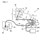
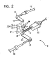
- the operating position select device 100 includes a select lever unit 1 manually operated by a driver, an operating angle sensor 200 for detecting an operating angle of the select lever 2, a mode shift unit 300 mounted on the automatic transmission 19, a first and a second control cable 8 and 18 connecting the select lever 2 to the mode shift unit 300, an assist actuator 9 for assisting operating force inputted to the select lever 2 by the driver, an operating torque sensor 21 for detecting operating force applied to the select lever 2, and a control unit 22 for controlling the assist actuator 9.
- the worm wheel 14 is provided on its upper surface with an electric terminal 24 contacting to a carbon resistor 25, indicated by a dashed line in FIG. 2, that is printed on a substrate fixed to a case of the assist actuator 9.
- the electric terminal 24 and the carbon resistor 25 constitute the operating angle sensor 200 for detecting an operating angle of the select lever 2 to output an operating angle signal to the control unit 22.
- the mode shift unit 300 shifts the operation modes of the automatic transmission 19 according to an operated position of the select lever 2.
- the mode shift unit 300 has a manual plate lever 20 and a detent mechanism 350 for keeping the manual plate lever 20 in a position selected by the select lever 2.
- the first control cable 8 rotates the coupling shaft 12, so that the terminal 24 on the worm wheel 14 united with the shaft 12 moves with respect to the carbon resistance 25 to change a relative angle between them.
- This relative angle corresponding to an operating angle of the select lever 2, is detected by the operating angle sensor 200, which outputs an operating angle signal to the control unit 22.
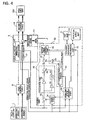
- the excessive movement prevention part 50 executes an excessive movement preventing process, and then the flow goes to step S11.
- the excessive movement preventing process will be described in detail later.
- the reaction force Fm acts on the select lever 2 against the operating force until the detent pin 29 reaches the peak of the cam 270 because the detent plate 27 united with the manual plate lever 300 is biased by the spring force of the spring plate 28 in a direction opposite to the operating direction.
- the operating force for moving the select lever 2 in the operating direction needs to overcome the reaction force produced by the spring force of the spring plate 28, and the lever 2 moves with increasing the amount of deformation of the spring plate 28. This results in increasing the reaction force acting on the lever 2.
- the spring plate 28 starts to reduce its amount of deformation with applying the spring force to the detent plate 27, so that the detent plate 27 is pressed to rotate so that the lever 2 is assisted to move forward.
- the reaction force Fm increases in the lever-assisting direction, and then decreases until the detent pin 29 reaches the bottom of the cam 270 corresponding the R position.
- This reversing characteristic of the reaction force causes affects a select feeling and/or an excessive movement of the select lever 2; the driver can hardly feel the select position and/or he or she moves the lever 2 so that it passes over the desired select position.
- This excessive movement operation depends heavily on operating velocity of the lever 2; the possibility of the excessive movement increase with the operating velocity.
- This operating position select device 100 of the first embodiment has many advantages described below.
Landscapes
- Engineering & Computer Science (AREA)
- General Engineering & Computer Science (AREA)
- Mechanical Engineering (AREA)
- Gear-Shifting Mechanisms (AREA)
Claims (6)
- Betriebspositionswähleinrichtung (100) für ein automatisches Getriebe (19), dessen Betriebsmoden schaltbar sind, wobei die Betriebspositionswähleinrichtung (100) umfaßt:eine Wählhebeleinheit (1) mit einem Wählhebel (2), der von einem Fahrer zwischen einer Mehrzahl von den Betriebsmoden entsprechenden Positionen betätigt wird,einen Betriebspositionssensor (200), der eine Betriebsposition des Wählhebels (2) detektiert und ein Betriebspositionssignal ausgibt,eine Modusumschalteinheit (300), die an dem automatischen Getriebe (19) anbringbar ist, um Betriebsmoden des automatischen Getriebes (19) zu schalten,ein mechanisches Verbindungsmittel (8, 18, 12), das mechanisch den Wählhebel (2) und die Modusschalteinheit (300) miteinander verbindet,ein Hilfsbetätigungsglied (9), das zwischen dem Wählhebel (2) und der Modusumschalteinheit (300) angeordnet ist und eine Hilfskraft zu dem Wählhebel (2) liefert,einen Betriebsgeschwindigkeitsdetektor (33), der die Betriebsgeschwindigkeit des Wählhebels (2) detektiert, undeine Steuereinheit (22), die das Hilfsbetätigungsglied (9) zumindest auf Basis des Betriebspositionssignals steuert, wobei die Steuereinheit (22) ein Verhinderungsteil (50) für zu große Bewegung aufweist, das den Wählhebel (2) daran hindert, sich über eine gewünschte Wahlposition hinaus zu bewegen, indem es die Hilfskraft verkleinert, wenn die von dem Betriebsgeschwindigkeitsdetektor (33) ausgegebene Betriebsgeschwindigkeit einen Geschwindigkeitsgrenzwert überschreitet.
- Betriebspositionswähleinrichtung (100) nach Anspruch 1,
wobei das Verhinderungsteil (33) für zu große Bewegung die Hilfskraft durch Erhöhung eines Überschußbetrages der Betriebsgeschwindigkeit über den Geschwindigkeitsgrenzwert vermindert. - Betriebspositionswähleinrichtung (100) nach Anspruch 1 oder 2,
wobei das Verhinderungsteil (33) für zu große Bewegung mit einer Geschwindigkeitskarte (51) für zu große Bewegung versehen ist, die Daten zu den Geschwindigkeitsgrenzwerten enthält, die auf Basis zumindest der Betriebsposition bestimmt wurden. - Betriebspositionswähleinrichtung (100) nach einem der Ansprüche 1 bis 3,
wobei das Verhinderungsteil (33) für große Bewegung mit einer Reaktionskraftkarte (52) versehen ist, die Daten zu der auf den Wählhebel (2) wirkenden Reaktionskraft enthält, die auf Basis zumindest der Betriebsposition bestimmt wurden. - Betriebspositionswähleinrichtung (100) nach Anspruch 4,
wobei die Daten der Reaktionskraftkarte (52) auf Basis zumindest der Betriebsposition oder der Betriebsgeschwindigkeit oder einer auf den Wählhebel (2) ausgeübten Betätigungskraft oder der Hilfskraft neugeschrieben werden. - Betriebspositionswähleinrichtung (100) nach einem der Ansprüche 1 bis 5,
wobei der Geschwindigkeitsgrenzwert einer Maximalgeschwindigkeit entspricht, bei welcher der Wählhebel (2) auf Basis zumindest der Betriebsgeschwindigkeit oder einer auf den Wählhebel (2) ausgeübten Betätigungskraft als innerhalb einer nahenden Wahlposition anhaltend abgeschätzt wird.
Applications Claiming Priority (2)
| Application Number | Priority Date | Filing Date | Title |
|---|---|---|---|
| JP2003369415A JP4360176B2 (ja) | 2003-07-04 | 2003-10-29 | 自動変速機のセレクトアシスト装置 |
| JP2003369415 | 2003-10-29 |
Publications (2)
| Publication Number | Publication Date |
|---|---|
| EP1528296A1 EP1528296A1 (de) | 2005-05-04 |
| EP1528296B1 true EP1528296B1 (de) | 2007-02-07 |
Family
ID=34420178
Family Applications (1)
| Application Number | Title | Priority Date | Filing Date |
|---|---|---|---|
| EP04292568A Expired - Lifetime EP1528296B1 (de) | 2003-10-29 | 2004-10-29 | Positionwahleinrichtung für ein automatisches Getriebe |
Country Status (3)
| Country | Link |
|---|---|
| US (1) | US7367244B2 (de) |
| EP (1) | EP1528296B1 (de) |
| DE (1) | DE602004004617T8 (de) |
Families Citing this family (11)
| Publication number | Priority date | Publication date | Assignee | Title |
|---|---|---|---|---|
| US7194927B2 (en) * | 2003-09-17 | 2007-03-27 | Calsonic Kansei Corporation | Operating position select device for automatic transmission |
| SE0400192L (sv) * | 2004-01-30 | 2004-12-14 | Volvo Lastvagnar Ab | Metod och anordning för att motverka olämplig manuell växling vid förutbestämda fordonstillstånd |
| JP4255889B2 (ja) * | 2004-07-07 | 2009-04-15 | 日産自動車株式会社 | 車両用自動変速装置のアシスト制御方法 |
| JP2007085411A (ja) * | 2005-09-21 | 2007-04-05 | Calsonic Kansei Corp | 自動変速機のセレクトアシスト装置 |
| US7571663B2 (en) * | 2005-10-29 | 2009-08-11 | Harold Vigil | Rotary shifter |
| JP2007336663A (ja) * | 2006-06-14 | 2007-12-27 | Denso Corp | 位置切換制御装置 |
| JP6173875B2 (ja) * | 2013-10-24 | 2017-08-02 | 日立オートモティブシステムズ株式会社 | 自動変速機のレンジ切換装置 |
| DE102013021235A1 (de) | 2013-12-13 | 2014-07-31 | Daimler Ag | Verfahren und Vorrichtung zur Steuerung eines automatisierten Fahrzeuggetriebes |
| WO2016139147A1 (en) * | 2015-03-04 | 2016-09-09 | Abb Ag | Safety control system and method of operation of a safety control system |
| CN105889496A (zh) * | 2016-06-21 | 2016-08-24 | 杭州虬龙科技有限公司 | 一种电控可限位推拉装置 |
| CN114397114B (zh) * | 2022-01-06 | 2024-04-09 | 一汽解放汽车有限公司 | 试验台架 |
Family Cites Families (15)
| Publication number | Priority date | Publication date | Assignee | Title |
|---|---|---|---|---|
| US5537885A (en) | 1994-08-04 | 1996-07-23 | Thomas; Gerald A. | Electronically controlled gear shift mechanism particularly suited for racing cars |
| US5758543A (en) * | 1996-05-06 | 1998-06-02 | Eaton Corporation | Shift lever assembly for minimizing jumpout |
| JPH09323559A (ja) | 1996-06-05 | 1997-12-16 | Nissan Motor Co Ltd | 自動変速機の操作装置 |
| US5868034A (en) * | 1997-04-08 | 1999-02-09 | Mcfadden; Patrick A. | Shifting apparatus for controlling a transmission shifter in a vehicle |
| JP2987121B2 (ja) | 1997-04-18 | 1999-12-06 | 京浜精密工業株式会社 | パワーシフタの制御装置 |
| US5904635A (en) * | 1997-08-07 | 1999-05-18 | Eaton Corporation | Partially automated lever-shifted mechanical transmission system |
| US6067871A (en) | 1997-09-12 | 2000-05-30 | Eaton Corporation | Variable resistance shift rail detent assembly and shift control method employing same |
| US6072390A (en) * | 1999-03-31 | 2000-06-06 | Daimlerchrysler Corporation | Position sensing system for manually operated shift lever of a vehicle transmission |
| FR2796116B1 (fr) | 1999-07-08 | 2001-09-07 | Siemens Automotive Sa | Dispositif de commande pour boite de vitesse controlee electriquement et procede associe |
| US6244127B1 (en) * | 1999-10-28 | 2001-06-12 | Teleflex, Incorporated | Mechanical or electrical transmission shifter |
| US6361473B1 (en) * | 2000-04-27 | 2002-03-26 | Eaton Corporation | System/method for synchronized shifting of a manually shifted transmission |
| DE10051210A1 (de) | 2000-10-16 | 2002-04-25 | Volkswagen Ag | Verfahren zur Steuerung des Gangstellers eines Kraftfahrzeuges |
| JP4183111B2 (ja) | 2001-09-27 | 2008-11-19 | ジヤトコ株式会社 | シフトバイワイヤシステム |
| DE602004001880T2 (de) | 2003-01-07 | 2007-04-05 | Calsonic Kansei Corp. | Wählhebel für Automatikgetriebe |
| US7231846B2 (en) * | 2004-08-25 | 2007-06-19 | Mack Trucks, Inc. | Magnetic fluid shifter damper mechanism |
-
2004
- 2004-10-28 US US10/974,975 patent/US7367244B2/en not_active Expired - Fee Related
- 2004-10-29 EP EP04292568A patent/EP1528296B1/de not_active Expired - Lifetime
- 2004-10-29 DE DE602004004617T patent/DE602004004617T8/de not_active Expired - Fee Related
Also Published As
| Publication number | Publication date |
|---|---|
| EP1528296A1 (de) | 2005-05-04 |
| DE602004004617T8 (de) | 2008-02-14 |
| US20050139030A1 (en) | 2005-06-30 |
| DE602004004617D1 (de) | 2007-03-22 |
| DE602004004617T2 (de) | 2007-11-08 |
| US7367244B2 (en) | 2008-05-06 |
Similar Documents
| Publication | Publication Date | Title |
|---|---|---|
| US7313980B2 (en) | Operating position select device for automatic transmission | |
| US7367244B2 (en) | Operating position select device for automatic transmission | |
| EP1437533B1 (de) | Wählhebel für Automatikgetriebe | |
| US7426881B2 (en) | Operating position select device for automatic transmission | |
| EP1517069B1 (de) | Positionswahleinrichtung für ein automatisches Getriebe | |
| US20060011003A1 (en) | Operating position select device for automatic transmission | |
| EP1519083A1 (de) | Positionswahleinrichtung für ein automatisches Getriebe | |
| US7243567B2 (en) | Operating position select device for automatic transmission | |
| US20050257637A1 (en) | Operating position select device for automatic transmission | |
| US20050247154A1 (en) | Operating position select device for automatic transmission | |
| US20060094565A1 (en) | Operating position select device for automatic transmission | |
| US20070068304A1 (en) | Operating position select device adapted for automatic transmission | |
| EP1355091B1 (de) | Steuervorrichtung für ein automatisiertes Fahrzeuggetriebe, mit Lernfähigkeit für die Gangpositionen | |
| JP2955092B2 (ja) | 車輛の電気制御自動変速機のシフト装置 | |
| JP2005121037A (ja) | 自動変速機のセレクトレバーアシスト装置 | |
| HK1060169B (en) | A control system for a robotized gearbox in a motor vehicle, with the ability to learn the position of the ratios or gears | |
| JP2005007970A (ja) | 自動変速機のセレクトアシスト装置 | |
| JP2005069441A (ja) | 自動変速機のセレクトアシスト装置 | |
| JP2005003085A (ja) | 自動変速機のセレクトアシスト装置 | |
| JP2005069443A (ja) | 自動変速機のセレクトアシスト装置 |
Legal Events
| Date | Code | Title | Description |
|---|---|---|---|
| PUAI | Public reference made under article 153(3) epc to a published international application that has entered the european phase |
Free format text: ORIGINAL CODE: 0009012 |
|
| AK | Designated contracting states |
Kind code of ref document: A1 Designated state(s): AT BE BG CH CY CZ DE DK EE ES FI FR GB GR HU IE IT LI LU MC NL PL PT RO SE SI SK TR |
|
| AX | Request for extension of the european patent |
Extension state: AL HR LT LV MK |
|
| 17P | Request for examination filed |
Effective date: 20050706 |
|
| AKX | Designation fees paid |
Designated state(s): DE FR GB |
|
| GRAP | Despatch of communication of intention to grant a patent |
Free format text: ORIGINAL CODE: EPIDOSNIGR1 |
|
| GRAS | Grant fee paid |
Free format text: ORIGINAL CODE: EPIDOSNIGR3 |
|
| GRAA | (expected) grant |
Free format text: ORIGINAL CODE: 0009210 |
|
| AK | Designated contracting states |
Kind code of ref document: B1 Designated state(s): DE FR GB |
|
| REG | Reference to a national code |
Ref country code: GB Ref legal event code: FG4D |
|
| REF | Corresponds to: |
Ref document number: 602004004617 Country of ref document: DE Date of ref document: 20070322 Kind code of ref document: P |
|
| ET | Fr: translation filed | ||
| PLBE | No opposition filed within time limit |
Free format text: ORIGINAL CODE: 0009261 |
|
| STAA | Information on the status of an ep patent application or granted ep patent |
Free format text: STATUS: NO OPPOSITION FILED WITHIN TIME LIMIT |
|
| 26N | No opposition filed |
Effective date: 20071108 |
|
| PGFP | Annual fee paid to national office [announced via postgrant information from national office to epo] |
Ref country code: DE Payment date: 20081027 Year of fee payment: 5 |
|
| PGFP | Annual fee paid to national office [announced via postgrant information from national office to epo] |
Ref country code: FR Payment date: 20081014 Year of fee payment: 5 |
|
| PGFP | Annual fee paid to national office [announced via postgrant information from national office to epo] |
Ref country code: GB Payment date: 20081029 Year of fee payment: 5 |
|
| REG | Reference to a national code |
Ref country code: FR Ref legal event code: ST Effective date: 20100630 |
|
| PG25 | Lapsed in a contracting state [announced via postgrant information from national office to epo] |
Ref country code: FR Free format text: LAPSE BECAUSE OF NON-PAYMENT OF DUE FEES Effective date: 20091102 Ref country code: DE Free format text: LAPSE BECAUSE OF NON-PAYMENT OF DUE FEES Effective date: 20100501 |
|
| PG25 | Lapsed in a contracting state [announced via postgrant information from national office to epo] |
Ref country code: GB Free format text: LAPSE BECAUSE OF NON-PAYMENT OF DUE FEES Effective date: 20091029 |