EP1528212B1 - Tür mit versetzter Drehachse - Google Patents
Tür mit versetzter Drehachse Download PDFInfo
- Publication number
- EP1528212B1 EP1528212B1 EP03360125A EP03360125A EP1528212B1 EP 1528212 B1 EP1528212 B1 EP 1528212B1 EP 03360125 A EP03360125 A EP 03360125A EP 03360125 A EP03360125 A EP 03360125A EP 1528212 B1 EP1528212 B1 EP 1528212B1
- Authority
- EP
- European Patent Office
- Prior art keywords
- door
- pegs
- guide system
- ceiling
- piece
- Prior art date
- Legal status (The legal status is an assumption and is not a legal conclusion. Google has not performed a legal analysis and makes no representation as to the accuracy of the status listed.)
- Expired - Lifetime
Links
- 238000006073 displacement reaction Methods 0.000 claims description 7
- 230000005489 elastic deformation Effects 0.000 claims description 2
- 241000920340 Pion Species 0.000 description 2
- 238000000034 method Methods 0.000 description 2
- 230000009977 dual effect Effects 0.000 description 1
- 239000012530 fluid Substances 0.000 description 1
- 238000003780 insertion Methods 0.000 description 1
- 230000037431 insertion Effects 0.000 description 1
- 230000002093 peripheral effect Effects 0.000 description 1
- 238000004804 winding Methods 0.000 description 1
Images


Classifications
-
- E—FIXED CONSTRUCTIONS
- E05—LOCKS; KEYS; WINDOW OR DOOR FITTINGS; SAFES
- E05D—HINGES OR SUSPENSION DEVICES FOR DOORS, WINDOWS OR WINGS
- E05D15/00—Suspension arrangements for wings
- E05D15/56—Suspension arrangements for wings with successive different movements
- E05D15/58—Suspension arrangements for wings with successive different movements with both swinging and sliding movements
- E05D15/582—Suspension arrangements for wings with successive different movements with both swinging and sliding movements with horizontal swinging axis
-
- E—FIXED CONSTRUCTIONS
- E06—DOORS, WINDOWS, SHUTTERS, OR ROLLER BLINDS IN GENERAL; LADDERS
- E06B—FIXED OR MOVABLE CLOSURES FOR OPENINGS IN BUILDINGS, VEHICLES, FENCES OR LIKE ENCLOSURES IN GENERAL, e.g. DOORS, WINDOWS, BLINDS, GATES
- E06B3/00—Window sashes, door leaves, or like elements for closing wall or like openings; Layout of fixed or moving closures, e.g. windows in wall or like openings; Features of rigidly-mounted outer frames relating to the mounting of wing frames
- E06B3/32—Arrangements of wings characterised by the manner of movement; Arrangements of movable wings in openings; Features of wings or frames relating solely to the manner of movement of the wing
- E06B3/50—Arrangements of wings characterised by the manner of movement; Arrangements of movable wings in openings; Features of wings or frames relating solely to the manner of movement of the wing with more than one kind of movement
- E06B3/5045—Arrangements of wings characterised by the manner of movement; Arrangements of movable wings in openings; Features of wings or frames relating solely to the manner of movement of the wing with more than one kind of movement specially adapted for furniture
-
- E—FIXED CONSTRUCTIONS
- E05—LOCKS; KEYS; WINDOW OR DOOR FITTINGS; SAFES
- E05D—HINGES OR SUSPENSION DEVICES FOR DOORS, WINDOWS OR WINGS
- E05D15/00—Suspension arrangements for wings
- E05D15/56—Suspension arrangements for wings with successive different movements
- E05D15/58—Suspension arrangements for wings with successive different movements with both swinging and sliding movements
- E05D15/582—Suspension arrangements for wings with successive different movements with both swinging and sliding movements with horizontal swinging axis
- E05D15/583—Suspension arrangements for wings with successive different movements with both swinging and sliding movements with horizontal swinging axis specially adapted for overhead wings
-
- E—FIXED CONSTRUCTIONS
- E05—LOCKS; KEYS; WINDOW OR DOOR FITTINGS; SAFES
- E05Y—INDEXING SCHEME ASSOCIATED WITH SUBCLASSES E05D AND E05F, RELATING TO CONSTRUCTION ELEMENTS, ELECTRIC CONTROL, POWER SUPPLY, POWER SIGNAL OR TRANSMISSION, USER INTERFACES, MOUNTING OR COUPLING, DETAILS, ACCESSORIES, AUXILIARY OPERATIONS NOT OTHERWISE PROVIDED FOR, APPLICATION THEREOF
- E05Y2900/00—Application of doors, windows, wings or fittings thereof
- E05Y2900/20—Application of doors, windows, wings or fittings thereof for furniture, e.g. cabinets
Definitions
- the present invention relates to a system for guiding a sliding door between two side walls of a parallelepiped-shaped box-type storage space, by means of a conventional sliding guide system, the door fitting into the volume. the box when in the open position.
- Boxes with doors obeying such an opening system are commonly used in the field of office furniture. These furniture elements are closed either by sliding movable flaps, formed of successive slats that provide deformability to the door, and allow its winding / unwinding inside the volume of the box, or by rigid doors.
- the invention relates to said rigid doors, generally formed of a non-deformable planar element obstructing, in the closed position, the opening of the box.
- elements of the type stud or roller are guided in a slide having a vertical section connected to a section section of horizontal appearance arranged near and often parallel to the ceiling of the box.
- these side edges are therefore arranged in front of the vertical portions of the track, which are therefore hidden.
- the axis of displacement of said protruding elements is in fact included in the middle plane of the door or in the immediate vicinity thereof.
- the document is known US 3,653,158 which describes a system for guiding a sliding door between two side walls of a box.
- the side walls are each provided with a slide with two communicating sections and rectilinear appearance.
- the displacement of the door is obtained by means of pins protruding laterally at its side edges and arranged symmetrically on either side of the door, sliding in the slideways with two pins per slide between a closed position and an open position in which the door is at least partially housed in the box near its ceiling.
- the object of the invention is therefore to provide a configuration in which it is possible to shift the door forward slides, for example to meet such an aesthetic requirement.
- the guidance system of the invention applies more specifically to a sliding door between two side walls of a box each provided with a slideway with two communicating sections of rectilinear shape, and allows the displacement of said door by means of pions protruding laterally at its side edges, arranged symmetrically on either side of the door and sliding in the slideways at the rate of two pins per slide.
- the pins are no longer disposed in the extension of the door, and their axes are therefore no longer contained or close to the average plane thereof, but offset from this plane.
- the pivot axis preferably remains in or in the immediate vicinity of this mean plane. From a functional point of view, this pivot axis must also be close to the upper edge of the door, to allow "storage thereof near the ceiling of the box.
- pivot axis of the door and the axis of the upper pins are relatively arranged in the pivoting part, such that when the door is closed, said upper pins are already placed in the portions of the slide rails.
- straight line oriented substantially parallel to the ceiling.
- pins when the pins are all in the portions of rails oriented substantially parallel to the ceiling, their axes preferably form a plane parallel to the mean plane of the door or slightly inclined relative thereto.
- the position of these is preferably surplus axially adjustable to allow an optimal operation of sliding by bringing the free ends of the pins of the bottom of the slides, to avoid any movement "crab" when moving the door.
- the pins form the axial end of adjustment pieces whose other end consists of two parallel branches whose outer surfaces are in contact with outer walls, one of the surface or the wall being provided with notches intended to cooperate with a relief of the other in a rack-type operation allowing, by elastic deformation of the branches, a discrete axial adjustment between several positions.
- said relief is actually also formed of notches which are homologous to the first ones and interact with them.
- This piece is further guided axially by at least one cylindrical orifice housing a central portion of the pin.
- the guidance is performed by a cylindrical housing actually made in the pivoting part.
- the guiding is performed simultaneously by an orifice made in the side edge of the door and by a coaxial orifice made in a tab parallel to said edge and located towards the inside of the door.
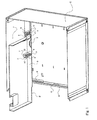
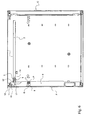
- Figure 1 shows only part of the box (C), to facilitate the explanation of the guide system of the invention.
- This allows, at the opening, the insertion of the door (P) parallel and in the vicinity of the ceiling (1) of the box (C).
- Guiding is effected by means of a slideway (2) comprising two rectilinear sections connected together, one of which is oriented parallel to the ceiling (1), while the other is oriented parallel to the opening of the box, that is, the plane of the door when closed.
- the two sections are in this case perpendicular to each other.
- Each slide (2) is traversed by two lateral pins, one (3) is directly attached to the side edge of the door, while the other (4) is integral with a piece (5) pivotally mounted on the door (P).
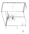
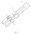
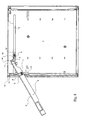
- the method of fixing the pin (3) to the door (P) appears more clearly in Figure 2. It is in fact the axial end of a part (6) (see Figure 4), the other end has two branches (7, 7 ').
- the pin (3) is guided by two coaxial orifices made in a tab (8) and the side edge (9) of the door (P).
- the branches (7, 7 ') cooperate with two walls (10, 10'). They comprise, on their external surfaces, notches (15, 15 ') which cooperate with homologous notches (16, 16') protruding from each wall (10, 10 ') to achieve a rack-and-pinion operation allowing a discrete axial adjustment thanks to to the elasticity of the branches (7, 7 ').
- the same type of pin (4) cooperates with a part (5) (see Figure 5) for pivoting the door (P).
- This pin (4) is always housed in the section of the slide (2) which is parallel to the ceiling (1) of the box (C), and it is guided axially for adjustment in a cylindrical housing (14). of the pivoting part (5).
- This housing (14) in fact separates two parts distinct from the pivoting part: a part comprising the parts (10, 10 ') provided with their notches (16, 16'), and a carriage part (13) guided in the slideway (2) .
- the wall (10) is further extended by a wing (17) provided with orifices (18) can accommodate a shaft (19) (see Figures 1, 2 and 3) materializing the axis around which is performed rotation.
- the housing (14) surrounds the central portion of the pin (4), located near the branches (7,7 ').
- These traditional systems based on mechanical linkages typically constituting a pantograph type configuration, weigh down the mechanical structure and make it much more expensive.
- the axial adjustment of each pin (3,4) ensures its correct positioning at the bottom of the slides to prevent said movement "crab".
- the discrete adjustment of each pin is for example in steps of 0.5 mm, said step being in fact fixed by the notching of the branches (7,7 ') and walls (10,10').
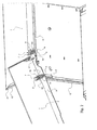
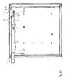
- FIG. 3 clearly shows that in a box configuration (C) as shown, with a peripheral opening frame made of a bevelled folded sheet (11), it is not possible to arrange the slide (2) near the outer edge (12) of said frame. In this case, if it is desired that the outer face of the door (P) is in the same plane as this edge (12), it is necessary to resort to a solution such as that of the invention, with a piece (5). ) to distinguish the axis of the pin (4) and that (19) of the pivoting with pins (3, 4) which are shifted inwardly of the box (C).
- the guide in the portion of the slide (2) oriented substantially parallel to the ceiling (1) of the box (C), is via a pin (4) but also by means of the carriage (13) of the piece (5) which is housed in said portion.
- This guiding mode does not allow the tilting of a portion to the other of the slide (2), the pivot piece (5) still remains housed in the slide portion (2) near the ceiling (1).
- FIGS. 6a to 6e which illustrate the operation of opening the door
- the axis of the pin (4) and that of the pivot (19) are doubly offset, along a vertical axis and according to a horizontal axis.
- the part (5) undergoes a translation movement during the opening operation and, in the configuration shown, so that the door (P) can be inserted in the vicinity of the ceiling (1) of the box (C ), it is necessary that its pivot axis is shifted upwards, that is to say located close to said ceiling (1).
- FIG 6c shows that in the following phase, when the pivoting of the door (P) is accentuated, the pin (4) and the piece (5) are inserted into the slide (2) towards the bottom of the box. (C), and the pin (3) takes off from the lower end of the slide (2).
- the door (P) When it reaches the upper end of said vertical section, the door (P) is in a horizontal position, that is to say parallel to the ceiling (1) of the box (C).
- the pin (3) is at the left end of the horizontal section of the slide (2), while the pin (4) is almost halfway of this slide (2). ).
Landscapes
- Engineering & Computer Science (AREA)
- Mechanical Engineering (AREA)
- Civil Engineering (AREA)
- Structural Engineering (AREA)
- Hinges (AREA)
- Wing Frames And Configurations (AREA)
- Casings For Electric Apparatus (AREA)
- Specific Sealing Or Ventilating Devices For Doors And Windows (AREA)
- Lighters Containing Fuel (AREA)
Claims (10)
- System zur Führung einer Tür (P), die zwischen zwei Seitenwänden eines Kastens (C) gleitet, welche jeweils mit einer Gleitschiene (2) mit zwei miteinander zusammenwirkenden Teilstücken mit geradlinigem Verlauf ausgestattet sind, wobei die Vorschiebung der Tür (P) mittels Stiften (3, 4) erfolgt, welche seitlich auf Höhe ihrer Seitenkanten überstehen, symmetrisch auf beiden Seiten der Tür (P) angeordnet und aufgrund zweier Stifte (3, 4) pro Gleitschiene (2) zwischen einer geschlossenen und einer geöffneten Position, in der die Tür (P) wenigstens teilweise in dem Kasten (C) nahe dessen Decke (1) angeordnet ist, gleitend, dadurch gekennzeichnet, dass die Achsen der Stifte (3, 4) zum Innern des Raums des Kastens (C) hin verschoben werden, wobei die beiden oberen Stifte (4), die nahe der Decke (1) angeordnet sind, wenn sich die Tür (P) in geschlossener Position befindet, jeweils mit einem Stück (5), das drehbar auf der Tür (P) um eine Achse (19) angeordnet ist, die nahe der Oberkante angeordnet ist, fest zusammengebaut sind.
- Führungssystem gemäß dem vorausgegangenen Anspruch, dadurch gekennzeichnet, dass sich die Drehachse (19) der Tür (P) in der Mittelebene der Tür (P) befindet.
- Führungssystem gemäß einem der vorausgegangenen Ansprüche, dadurch gekennzeichnet, dass die Drehachse (19) der Tür (P) und die Achse der oberen Stifte (4) relativ zueinander in dem Drehstück (5) so angeordnet sind, dass, wenn die Tür (P) geschlossen ist, die oberen Stifte (4) in den Bereichen der Gleitschienen (2) mit geradem Verlauf angeordnet sind, die im Wesentlichen parallel zur Decke (1) ausgerichtet sind.
- Führungssystem gemäß einem der vorausgegangenen Ansprüche, dadurch gekennzeichnet, dass, wenn sich die Stifte (3, 4) alle in den Bereichen der Gleitschienen (2) mit geradem Verlauf befinden, die im Wesentlichen parallel zur Decke (1) ausgerichtet sind, deren Achsen eine Ebene bilden, die zur Mittelebene der Tür (P) parallel oder bezogen auf die Letztgenannte leicht geneigt ist.
- Führungssystem gemäß einem der vorausgegangenen Ansprüche, dadurch gekennzeichnet, dass die Position der Stifte (3, 4) axial eingestellt werden kann.
- Führungssystem gemäß dem vorausgegangenen Anspruch, dadurch gekennzeichnet, dass die Stifte (3, 4) das axiale Ende der Einstellungsstücke bilden, deren anderes Ende aus zwei parallelen Armen (7, 7') gebildet ist, deren Außenflächen in Kontakt mit den Außenwänden (10, 10') sind, wobei entweder die Fläche oder die Wand mit Rastkerben (15, 15') versehen ist, die dazu bestimmt sind, mit einem Relief der anderen in einer Funktion der Art Zahnstange zusammenzuwirken, wodurch mittels elastischer Verformung der Arme (7, 7') ein unauffälliges axiales Einstellen des Stücks zwischen mehreren Positionen ermöglicht wird.
- Führungssystem gemäß dem vorausgegangenen Anspruch, dadurch gekennzeichnet, dass die Unebenheit gleichermaßen aus Rastkerben (16, 16') gebildet ist, die zu den ersten (15, 15') gleichförmig sind.
- Führungssystem gemäß einem der Ansprüche 6 und 7, dadurch gekennzeichnet, dass das Stück zum Einstellen axial durch wenigstens eine zylinderförmige Öffnung geführt wird, in der ein mittlerer Bereich des Stifts untergebracht ist.
- Führungssystem gemäß dem vorausgegangenen Anspruch, dadurch gekennzeichnet, dass im Fall der oberen Stifte (4) die Führung mittels eines zylinderförmigen Sitzes (14) bewirkt wird, der in dem Drehstück (5) vorgesehen ist.
- Führungssystem gemäß Anspruch 8, dadurch gekennzeichnet, dass in dem Fall anderer Stifte (3) die Führung gleichzeitig mittels einer Öffnung, die in der Seitenkante (9) der Tür (P) vorgesehen ist, und mittels einer koaxialen Öffnung bewirkt wird, die in einer Klaue (8) parallel zur Kante (9) zum Innern der Tür (P) angeordnet ist.
Priority Applications (4)
| Application Number | Priority Date | Filing Date | Title |
|---|---|---|---|
| DE60318587T DE60318587D1 (de) | 2003-10-29 | 2003-10-29 | Tür mit versetzter Drehachse |
| AT03360125T ATE383489T1 (de) | 2003-10-29 | 2003-10-29 | Tür mit versetzter drehachse |
| EP03360125A EP1528212B1 (de) | 2003-10-29 | 2003-10-29 | Tür mit versetzter Drehachse |
| PCT/FR2004/002768 WO2005042900A1 (fr) | 2003-10-29 | 2004-10-27 | Porte a axe de pivotement decale |
Applications Claiming Priority (1)
| Application Number | Priority Date | Filing Date | Title |
|---|---|---|---|
| EP03360125A EP1528212B1 (de) | 2003-10-29 | 2003-10-29 | Tür mit versetzter Drehachse |
Publications (2)
| Publication Number | Publication Date |
|---|---|
| EP1528212A1 EP1528212A1 (de) | 2005-05-04 |
| EP1528212B1 true EP1528212B1 (de) | 2008-01-09 |
Family
ID=34400608
Family Applications (1)
| Application Number | Title | Priority Date | Filing Date |
|---|---|---|---|
| EP03360125A Expired - Lifetime EP1528212B1 (de) | 2003-10-29 | 2003-10-29 | Tür mit versetzter Drehachse |
Country Status (4)
| Country | Link |
|---|---|
| EP (1) | EP1528212B1 (de) |
| AT (1) | ATE383489T1 (de) |
| DE (1) | DE60318587D1 (de) |
| WO (1) | WO2005042900A1 (de) |
Cited By (1)
| Publication number | Priority date | Publication date | Assignee | Title |
|---|---|---|---|---|
| WO2021161056A1 (de) | 2020-02-14 | 2021-08-19 | Steelcase Inc. | Möbelstück, insbesondere ein schrank |
Families Citing this family (2)
| Publication number | Priority date | Publication date | Assignee | Title |
|---|---|---|---|---|
| DE202008006754U1 (de) * | 2008-05-19 | 2009-10-01 | Hettich-Heinze Gmbh & Co. Kg | Justiereinrichtung für eine in einen Möbelkorpus einschieb- und ausziehbare Frontklappe |
| IT1403670B1 (it) * | 2011-02-02 | 2013-10-31 | Bruno Fattorini & Partners Srl | Dispositivo di incernieramento, particolarmente per ante di contenitori e simili. |
Family Cites Families (6)
| Publication number | Priority date | Publication date | Assignee | Title |
|---|---|---|---|---|
| US1678453A (en) * | 1925-09-08 | 1928-07-24 | Welch Mfg Company | Door structure for display cabinets |
| FR760931A (fr) * | 1933-09-18 | 1934-03-06 | Sanitas Ets | Volet roulant notamment pour tables, guéridons, vitrines, placards, etc. |
| DE1216732B (de) * | 1955-03-18 | 1966-05-12 | Robert Krause K G Zweigniederl | Beschlag fuer eine Drehschiebetuer |
| FR1202659A (fr) * | 1958-09-20 | 1960-01-12 | Porte rigide escamotable, pour meubles ou autres applications | |
| US3653158A (en) * | 1970-06-22 | 1972-04-04 | Westinghouse Electric Corp | Arrangement for supporting a closure member from a track |
| US5083847A (en) * | 1991-01-28 | 1992-01-28 | Transfer Flow International, Inc. | Pocket door attachment fitting for a cabinet |
-
2003
- 2003-10-29 DE DE60318587T patent/DE60318587D1/de not_active Expired - Lifetime
- 2003-10-29 EP EP03360125A patent/EP1528212B1/de not_active Expired - Lifetime
- 2003-10-29 AT AT03360125T patent/ATE383489T1/de not_active IP Right Cessation
-
2004
- 2004-10-27 WO PCT/FR2004/002768 patent/WO2005042900A1/fr not_active Ceased
Cited By (1)
| Publication number | Priority date | Publication date | Assignee | Title |
|---|---|---|---|---|
| WO2021161056A1 (de) | 2020-02-14 | 2021-08-19 | Steelcase Inc. | Möbelstück, insbesondere ein schrank |
Also Published As
| Publication number | Publication date |
|---|---|
| EP1528212A1 (de) | 2005-05-04 |
| DE60318587D1 (de) | 2008-02-21 |
| WO2005042900A1 (fr) | 2005-05-12 |
| ATE383489T1 (de) | 2008-01-15 |
Similar Documents
| Publication | Publication Date | Title |
|---|---|---|
| EP0290304B1 (de) | Profil zur Verwirklichung eines Badewannenpaneelgefüges und Gefüge, das mit diesem Paneel hergestellt ist | |
| EP0911469B1 (de) | Drehbare Tür mit einem Flügel, an dem zwei parallele Treibstangen mittels zweiarmiger Hebel montiert sind | |
| FR2706120A3 (fr) | Charnière pour appareils électroménagers encastrables, en particulier pour réfrigérateurs . | |
| FR2705722A1 (fr) | Dispositif de manÓoeuvre de serrures par poussée ou traction. | |
| FR2858008A3 (fr) | Moyen de transport et dispositif de tamissage de lumiere a utiliser avec ce moyen de support, et fenetre comportant ce moyen de support | |
| EP1528212B1 (de) | Tür mit versetzter Drehachse | |
| EP2832949B1 (de) | Steuerungssystem für die Lamellen von Jalousien, und entsprechende Jalousie | |
| EP2840220B1 (de) | Steuerungssystem für Jalousielamellen | |
| FR2588605A1 (fr) | Systeme manoeuvrable d'arret d'un battant de volet et ensemble de crochetage dudit battant. | |
| EP1524399A1 (de) | Schutzgitter | |
| EP2386706B1 (de) | Verrieglungsvorrichtung für halbfesten Fensterflügel | |
| FR2667647A1 (fr) | Systeme manóoeuvrable d'arret d'un battant de volet et ensemble de crochetage dudit battant. | |
| EP1396603B1 (de) | Sektionaltorblatt und damit versehenes Tor | |
| EP0697494B1 (de) | Führungsschiene für Schiebevorhänge | |
| EP1913842A1 (de) | Möbelschubladenführung | |
| FR2526530A1 (fr) | Refrigerateur | |
| FR2765911A1 (fr) | Dispositif de blocage pour volet roulant | |
| FR2629856A1 (de) | ||
| CH684151A5 (fr) | Fermoir de bracelet. | |
| EP2061944B1 (de) | Scharnierbaugruppe zur koplanaren fixierung | |
| FR2825406A1 (fr) | Dispositif de montage a articulation d'un ouvrant sur un dormant et armoire electrique a deux sens d'ouverture comportant un tel dispositif | |
| FR2806437A1 (fr) | Logement de pivot de basculement pour dispositif oscillobattants | |
| FR2487899A1 (fr) | Coulisse perfectionnee de porte battante | |
| EP4541222A1 (de) | Faltverschluss für armband, insbesondere für armbanduhren | |
| EP0643191A1 (de) | Schiebeflügel |
Legal Events
| Date | Code | Title | Description |
|---|---|---|---|
| PUAI | Public reference made under article 153(3) epc to a published international application that has entered the european phase |
Free format text: ORIGINAL CODE: 0009012 |
|
| AK | Designated contracting states |
Kind code of ref document: A1 Designated state(s): AT BE BG CH CY CZ DE DK EE ES FI FR GB GR HU IE IT LI LU MC NL PT RO SE SI SK TR |
|
| AX | Request for extension of the european patent |
Extension state: AL LT LV MK |
|
| 17P | Request for examination filed |
Effective date: 20050506 |
|
| AKX | Designation fees paid |
Designated state(s): AT BE BG CH CY CZ DE DK EE ES FI FR GB GR HU IE IT LI LU MC NL PT RO SE SI SK TR |
|
| GRAP | Despatch of communication of intention to grant a patent |
Free format text: ORIGINAL CODE: EPIDOSNIGR1 |
|
| GRAS | Grant fee paid |
Free format text: ORIGINAL CODE: EPIDOSNIGR3 |
|
| GRAA | (expected) grant |
Free format text: ORIGINAL CODE: 0009210 |
|
| AK | Designated contracting states |
Kind code of ref document: B1 Designated state(s): AT BE BG CH CY CZ DE DK EE ES FI FR GB GR HU IE IT LI LU MC NL PT RO SE SI SK TR |
|
| REG | Reference to a national code |
Ref country code: GB Ref legal event code: FG4D Free format text: NOT ENGLISH |
|
| REG | Reference to a national code |
Ref country code: CH Ref legal event code: EP |
|
| REG | Reference to a national code |
Ref country code: IE Ref legal event code: FG4D Free format text: LANGUAGE OF EP DOCUMENT: FRENCH |
|
| REF | Corresponds to: |
Ref document number: 60318587 Country of ref document: DE Date of ref document: 20080221 Kind code of ref document: P |
|
| PG25 | Lapsed in a contracting state [announced via postgrant information from national office to epo] |
Ref country code: SI Free format text: LAPSE BECAUSE OF FAILURE TO SUBMIT A TRANSLATION OF THE DESCRIPTION OR TO PAY THE FEE WITHIN THE PRESCRIBED TIME-LIMIT Effective date: 20080109 Ref country code: NL Free format text: LAPSE BECAUSE OF FAILURE TO SUBMIT A TRANSLATION OF THE DESCRIPTION OR TO PAY THE FEE WITHIN THE PRESCRIBED TIME-LIMIT Effective date: 20080109 |
|
| NLV1 | Nl: lapsed or annulled due to failure to fulfill the requirements of art. 29p and 29m of the patents act | ||
| PG25 | Lapsed in a contracting state [announced via postgrant information from national office to epo] |
Ref country code: FI Free format text: LAPSE BECAUSE OF FAILURE TO SUBMIT A TRANSLATION OF THE DESCRIPTION OR TO PAY THE FEE WITHIN THE PRESCRIBED TIME-LIMIT Effective date: 20080109 Ref country code: ES Free format text: LAPSE BECAUSE OF FAILURE TO SUBMIT A TRANSLATION OF THE DESCRIPTION OR TO PAY THE FEE WITHIN THE PRESCRIBED TIME-LIMIT Effective date: 20080420 |
|
| GBV | Gb: ep patent (uk) treated as always having been void in accordance with gb section 77(7)/1977 [no translation filed] | ||
| PG25 | Lapsed in a contracting state [announced via postgrant information from national office to epo] |
Ref country code: AT Free format text: LAPSE BECAUSE OF FAILURE TO SUBMIT A TRANSLATION OF THE DESCRIPTION OR TO PAY THE FEE WITHIN THE PRESCRIBED TIME-LIMIT Effective date: 20080109 Ref country code: BG Free format text: LAPSE BECAUSE OF FAILURE TO SUBMIT A TRANSLATION OF THE DESCRIPTION OR TO PAY THE FEE WITHIN THE PRESCRIBED TIME-LIMIT Effective date: 20080409 |
|
| PG25 | Lapsed in a contracting state [announced via postgrant information from national office to epo] |
Ref country code: PT Free format text: LAPSE BECAUSE OF FAILURE TO SUBMIT A TRANSLATION OF THE DESCRIPTION OR TO PAY THE FEE WITHIN THE PRESCRIBED TIME-LIMIT Effective date: 20080609 |
|
| REG | Reference to a national code |
Ref country code: IE Ref legal event code: FD4D |
|
| PG25 | Lapsed in a contracting state [announced via postgrant information from national office to epo] |
Ref country code: SE Free format text: LAPSE BECAUSE OF FAILURE TO SUBMIT A TRANSLATION OF THE DESCRIPTION OR TO PAY THE FEE WITHIN THE PRESCRIBED TIME-LIMIT Effective date: 20080409 Ref country code: SK Free format text: LAPSE BECAUSE OF FAILURE TO SUBMIT A TRANSLATION OF THE DESCRIPTION OR TO PAY THE FEE WITHIN THE PRESCRIBED TIME-LIMIT Effective date: 20080109 Ref country code: CZ Free format text: LAPSE BECAUSE OF FAILURE TO SUBMIT A TRANSLATION OF THE DESCRIPTION OR TO PAY THE FEE WITHIN THE PRESCRIBED TIME-LIMIT Effective date: 20080109 Ref country code: IE Free format text: LAPSE BECAUSE OF FAILURE TO SUBMIT A TRANSLATION OF THE DESCRIPTION OR TO PAY THE FEE WITHIN THE PRESCRIBED TIME-LIMIT Effective date: 20080109 Ref country code: DK Free format text: LAPSE BECAUSE OF FAILURE TO SUBMIT A TRANSLATION OF THE DESCRIPTION OR TO PAY THE FEE WITHIN THE PRESCRIBED TIME-LIMIT Effective date: 20080109 |
|
| PLBE | No opposition filed within time limit |
Free format text: ORIGINAL CODE: 0009261 |
|
| STAA | Information on the status of an ep patent application or granted ep patent |
Free format text: STATUS: NO OPPOSITION FILED WITHIN TIME LIMIT |
|
| PG25 | Lapsed in a contracting state [announced via postgrant information from national office to epo] |
Ref country code: RO Free format text: LAPSE BECAUSE OF FAILURE TO SUBMIT A TRANSLATION OF THE DESCRIPTION OR TO PAY THE FEE WITHIN THE PRESCRIBED TIME-LIMIT Effective date: 20080109 |
|
| 26N | No opposition filed |
Effective date: 20081010 |
|
| PG25 | Lapsed in a contracting state [announced via postgrant information from national office to epo] |
Ref country code: GB Free format text: LAPSE BECAUSE OF FAILURE TO SUBMIT A TRANSLATION OF THE DESCRIPTION OR TO PAY THE FEE WITHIN THE PRESCRIBED TIME-LIMIT Effective date: 20080109 |
|
| PG25 | Lapsed in a contracting state [announced via postgrant information from national office to epo] |
Ref country code: DE Free format text: LAPSE BECAUSE OF FAILURE TO SUBMIT A TRANSLATION OF THE DESCRIPTION OR TO PAY THE FEE WITHIN THE PRESCRIBED TIME-LIMIT Effective date: 20080410 |
|
| BERE | Be: lapsed |
Owner name: STEELCASE S.A. Effective date: 20081031 |
|
| PG25 | Lapsed in a contracting state [announced via postgrant information from national office to epo] |
Ref country code: EE Free format text: LAPSE BECAUSE OF FAILURE TO SUBMIT A TRANSLATION OF THE DESCRIPTION OR TO PAY THE FEE WITHIN THE PRESCRIBED TIME-LIMIT Effective date: 20080109 |
|
| PG25 | Lapsed in a contracting state [announced via postgrant information from national office to epo] |
Ref country code: MC Free format text: LAPSE BECAUSE OF NON-PAYMENT OF DUE FEES Effective date: 20081031 |
|
| REG | Reference to a national code |
Ref country code: CH Ref legal event code: PL |
|
| REG | Reference to a national code |
Ref country code: FR Ref legal event code: ST Effective date: 20090630 |
|
| PG25 | Lapsed in a contracting state [announced via postgrant information from national office to epo] |
Ref country code: CY Free format text: LAPSE BECAUSE OF FAILURE TO SUBMIT A TRANSLATION OF THE DESCRIPTION OR TO PAY THE FEE WITHIN THE PRESCRIBED TIME-LIMIT Effective date: 20080109 |
|
| PG25 | Lapsed in a contracting state [announced via postgrant information from national office to epo] |
Ref country code: IT Free format text: LAPSE BECAUSE OF FAILURE TO SUBMIT A TRANSLATION OF THE DESCRIPTION OR TO PAY THE FEE WITHIN THE PRESCRIBED TIME-LIMIT Effective date: 20080109 |
|
| PG25 | Lapsed in a contracting state [announced via postgrant information from national office to epo] |
Ref country code: BE Free format text: LAPSE BECAUSE OF NON-PAYMENT OF DUE FEES Effective date: 20081031 |
|
| PG25 | Lapsed in a contracting state [announced via postgrant information from national office to epo] |
Ref country code: CH Free format text: LAPSE BECAUSE OF NON-PAYMENT OF DUE FEES Effective date: 20081031 Ref country code: LI Free format text: LAPSE BECAUSE OF NON-PAYMENT OF DUE FEES Effective date: 20081031 Ref country code: FR Free format text: LAPSE BECAUSE OF NON-PAYMENT OF DUE FEES Effective date: 20081031 |
|
| PG25 | Lapsed in a contracting state [announced via postgrant information from national office to epo] |
Ref country code: HU Free format text: LAPSE BECAUSE OF FAILURE TO SUBMIT A TRANSLATION OF THE DESCRIPTION OR TO PAY THE FEE WITHIN THE PRESCRIBED TIME-LIMIT Effective date: 20080710 Ref country code: LU Free format text: LAPSE BECAUSE OF NON-PAYMENT OF DUE FEES Effective date: 20081029 |
|
| PG25 | Lapsed in a contracting state [announced via postgrant information from national office to epo] |
Ref country code: TR Free format text: LAPSE BECAUSE OF FAILURE TO SUBMIT A TRANSLATION OF THE DESCRIPTION OR TO PAY THE FEE WITHIN THE PRESCRIBED TIME-LIMIT Effective date: 20080109 |
|
| PG25 | Lapsed in a contracting state [announced via postgrant information from national office to epo] |
Ref country code: GR Free format text: LAPSE BECAUSE OF FAILURE TO SUBMIT A TRANSLATION OF THE DESCRIPTION OR TO PAY THE FEE WITHIN THE PRESCRIBED TIME-LIMIT Effective date: 20080410 |