EP1527743B1 - Dispositif médical pour électrotomie - Google Patents
Dispositif médical pour électrotomie Download PDFInfo
- Publication number
- EP1527743B1 EP1527743B1 EP04090402A EP04090402A EP1527743B1 EP 1527743 B1 EP1527743 B1 EP 1527743B1 EP 04090402 A EP04090402 A EP 04090402A EP 04090402 A EP04090402 A EP 04090402A EP 1527743 B1 EP1527743 B1 EP 1527743B1
- Authority
- EP
- European Patent Office
- Prior art keywords
- gripping
- medical device
- instrument
- device assembly
- assembly according
- Prior art date
- Legal status (The legal status is an assumption and is not a legal conclusion. Google has not performed a legal analysis and makes no representation as to the accuracy of the status listed.)
- Not-in-force
Links
Images


Classifications
-
- A—HUMAN NECESSITIES
- A61—MEDICAL OR VETERINARY SCIENCE; HYGIENE
- A61B—DIAGNOSIS; SURGERY; IDENTIFICATION
- A61B18/00—Surgical instruments, devices or methods for transferring non-mechanical forms of energy to or from the body
- A61B18/04—Surgical instruments, devices or methods for transferring non-mechanical forms of energy to or from the body by heating
- A61B18/12—Surgical instruments, devices or methods for transferring non-mechanical forms of energy to or from the body by heating by passing a current through the tissue to be heated, e.g. high-frequency current
- A61B18/14—Probes or electrodes therefor
- A61B18/1402—Probes for open surgery
-
- A—HUMAN NECESSITIES
- A61—MEDICAL OR VETERINARY SCIENCE; HYGIENE
- A61B—DIAGNOSIS; SURGERY; IDENTIFICATION
- A61B18/00—Surgical instruments, devices or methods for transferring non-mechanical forms of energy to or from the body
- A61B18/04—Surgical instruments, devices or methods for transferring non-mechanical forms of energy to or from the body by heating
- A61B18/08—Surgical instruments, devices or methods for transferring non-mechanical forms of energy to or from the body by heating by means of electrically-heated probes
-
- A—HUMAN NECESSITIES
- A61—MEDICAL OR VETERINARY SCIENCE; HYGIENE
- A61B—DIAGNOSIS; SURGERY; IDENTIFICATION
- A61B17/00—Surgical instruments, devices or methods, e.g. tourniquets
- A61B17/30—Surgical pincettes without pivotal connections
-
- A—HUMAN NECESSITIES
- A61—MEDICAL OR VETERINARY SCIENCE; HYGIENE
- A61B—DIAGNOSIS; SURGERY; IDENTIFICATION
- A61B18/00—Surgical instruments, devices or methods for transferring non-mechanical forms of energy to or from the body
- A61B18/04—Surgical instruments, devices or methods for transferring non-mechanical forms of energy to or from the body by heating
- A61B18/12—Surgical instruments, devices or methods for transferring non-mechanical forms of energy to or from the body by heating by passing a current through the tissue to be heated, e.g. high-frequency current
- A61B18/14—Probes or electrodes therefor
- A61B18/1442—Probes having pivoting end effectors, e.g. forceps
-
- A—HUMAN NECESSITIES
- A61—MEDICAL OR VETERINARY SCIENCE; HYGIENE
- A61B—DIAGNOSIS; SURGERY; IDENTIFICATION
- A61B18/00—Surgical instruments, devices or methods for transferring non-mechanical forms of energy to or from the body
- A61B2018/00571—Surgical instruments, devices or methods for transferring non-mechanical forms of energy to or from the body for achieving a particular surgical effect
- A61B2018/00601—Cutting
-
- A—HUMAN NECESSITIES
- A61—MEDICAL OR VETERINARY SCIENCE; HYGIENE
- A61B—DIAGNOSIS; SURGERY; IDENTIFICATION
- A61B18/00—Surgical instruments, devices or methods for transferring non-mechanical forms of energy to or from the body
- A61B18/04—Surgical instruments, devices or methods for transferring non-mechanical forms of energy to or from the body by heating
- A61B18/12—Surgical instruments, devices or methods for transferring non-mechanical forms of energy to or from the body by heating by passing a current through the tissue to be heated, e.g. high-frequency current
- A61B18/14—Probes or electrodes therefor
- A61B2018/1405—Electrodes having a specific shape
- A61B2018/1407—Loop
Definitions
- the invention relates to a medical device arrangement for the separation or removal of body tissue by means of electrotomy.
- the medical device assembly includes a high frequency AC generator and a cutting instrument.
- the invention also relates to a gripping instrument for use with the medical device assembly, a cutting instrument for the medical device assembly and a corresponding converter unit.
- the electrosurgical application technique is used according to the prior art in the so-called monopolar application technique, that is, in addition to the cutting electrode formed as an active electrode a large return electrode (also called neutral electrode) attached to the extremities of the patient to be treated to ensure a high-frequency current flow.
- This monopolar application technique has the disadvantage that the current flows through the entire patient.
- the disadvantage results from the fact that the monopolar application technique represents an inherent danger potential for the patient and the user, since the current flows through the entire patient and burns due to stray leakage currents and a neutral electrode can not be ruled out.
- the disadvantage also results from the fact that part of the energy required for the electrotomy, in particular the spark discharge, is converted into heat on its way to the neutral electrode, so that the efficiency of a corresponding arrangement is poor.
- the Japanese Patent Application JP 2001-029353 A discloses an electrosurgical device including a generator, a grasper instrument, and an ultrasound surgery instrument operable to flow a high frequency alternating current between the gripping instrument and the ultrasound surgery instrument.
- the invention is therefore based on the object to provide a medical device assembly and components for cutting body tissue, which avoids the aforementioned disadvantages as possible. Likewise, components are to be given for such an arrangement.
- FIG. 1 shows a control unit 1 with integrated generator.
- the control unit has a control terminal 3 to which a foot switch 4 is connected.
- the control unit 1 has a bipolar terminal 2 to which electrical leads 16 and a line branch 7 on the one hand a cutting instrument 10 and on the other hand, a gripping instrument 12 are connected, in such a way that a high-frequency alternating bipolar between a cutting electrode 23 of the cutting instrument 10 on the one hand and Gripping surfaces 32 of the gripping instrument 12 as a counter electrode on the other hand is applied as soon as the foot switch 4 is actuated.
- the control unit 1 comprises a generator and pressure switches 5 and 6, which cause, depending on which of the two switches is actuated, at the bipolar output 2, either an alternating current with a peak peak amplitude of 80 V required for interstitial thermotherapy (RFITT) is applied or an alternating current suitable for cutting with a peak peak amplitude of 200 V.
- RFITT interstitial thermotherapy
- FIG. 2 shows those components of a medical device assembly to be connected to a generator for a high-frequency alternating current.
- the generator itself is not shown.
- FIG. 2 In FIG. 2 are shown on the one hand, a cutting instrument 10 'and designed as tweezers gripping instrument 12. Also shows FIG. 2 schematically a converter unit 14, to which on the one hand the cutting instrument 10 'and on the other hand, the gripping instrument 12 is connected via corresponding electrical leads 16.
- the converter unit 14 has on the input side a cable 18 with connecting plug 20 connected thereto for connecting the converter unit 14 to a generator.
- the cutting instrument 10 has a cutting electrode 22, which is arranged distally on an electrode shaft 24 and is connected via the electrode shaft 24 with a handle 26 of the cutting instrument.
- Cutting electrode 22 together with electrode shaft 24 are detachably connected to the handle 26, so that the cutting electrode 22 together with the electrode shaft 24 is to be replaced after an operation, while the handle 26 is to be used again.
- On the handle 26 is a connection for that electrical supply line 16, with which the cutting instrument 10 is connected to the converter unit 14. This electrical connection is solvable.
- a pressure switch is disposed in the region of the handle 26, which is to be operated with a finger and can interrupt or restore an electrical connection to the cutting electrode 22.
- a cutting electrode in the form of a wire loop 23 may also be provided, as shown in FIG FIG. 1 is shown.
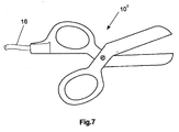
- FIG. 7 an alternative cutting instrument in the form of a coagulating scissors 10 ".
- This scissors 10" is to be connected to the control unit 1 via an electrical supply line 16, with the result that an electrical potential is to be applied to the cutting edges of the scissors.
- This makes it possible to cut with the scissors, as known from conventional scissors, while at the same time due to the applied potential in the region of the cut occurs a tissue obliteration (coagulation), which closes any cut blood vessels immediately.
- the gripper instrument 12 ' is formed according to the first variant described above as a bipolar forceps and therefore connected via two electrical leads 16 to one pole of the converter unit 14 and the converter unit 14 to a pole of the generator.
- the gripping instrument 12 ' has two gripping arms 30 which have gripping surfaces 32 facing each other at the distal end. Each of the two gripping surfaces 32 is electrically connected to one of the electrical leads 16 and at least partially electrically conductive.
- the gripping surfaces 32 point in FIG. 1 unrecognizable Elevations in the form of barrel teeth 34 on how the FIG. 5 can be seen.
- FIG. 1 unrecognizable Elevations in the form of barrel teeth 34 on how the FIG. 5 can be seen.
- a respective gripping surface 32 together with the barrel teeth 34 are part of a gripping lug 36 which consists of stainless steel and is to be pushed onto the distal end of a respective gripping arm 32 of the gripping instrument 12. In this way, after an operation, the corresponding gripping lugs can be replaced and the remaining gripping instrument 12 can be used again.
- FIG. 6 shows an alternative design of the distal end of the gripping arms 30 'of a gripping instrument 12 or 12', as shown in FIGS. 1 or 2 is shown.
- FIG. 6a shows the gripping arms 30 'in side view.
- FIGS. 6b and c the distal end of the gripping arms 30 'is shown in perspective once in the closed and once in the opened state.
- the gripping instrument is not designed as conventional tweezers, but as self-closing tweezers, as in FIG. 1 in the form of the gripping instrument 12 is shown schematically.
- a compression spring 8 causes the gripping instrument 12 closes automatically and can be opened by pressure on the gripping surfaces 9 against the spring force of the compression spring 8.
- Such a gripping instrument 12 has the advantage that the attending physician with the hand guiding the gripping instrument 12 does not have to simultaneously constantly exert the required holding force.
- FIG. 3 shows a circuit diagram of the converter unit 14, which shows that the converter unit 14 has a transformer 40 having a primary winding 42 which is intended for connection to the generator and a secondary winding 44, on the one hand with a connection 46 for the cutting instrument and on the other hand is connected to two parallel connections 48 for the gripping instrument. Between the secondary winding 44 and the cutting electrode 46, a first capacitor 50 is arranged. On the other side of the secondary winding, a second capacitor 52 is disposed between the secondary winding 44 and the terminals 48. First and second capacitors 50 and 52 can be exchanged for impedance matching. The Furthermore, capacitors have the effect of suppressing DC components and thus Faraday effects.
- the transformer 40 is otherwise a high-frequency transformer in which the ratio of the number of turns n 2 of the secondary winding 44 to the number of turns n 1 of the primary winding 42 n 2 > n 1 .
- Such a high-frequency transformer transforms a low, for the purpose of tissue coagulation output voltage of a conventional generator (in some 80 V) high voltage values that allow the ignition of a spark of a cutting electrode and thus the cutting of biological tissue.
- the output voltage at the converter unit 14 is for example about 200 V.
- FIG. 4 is similar to a medical device array FIG. 1 illustrated in which a converter unit 14, as in the Figures 2 and 3 shown, between control unit 1 'on the one hand and gripping and cutting instrument 12 or 10' on the other hand, is connected.
- the converter unit 14 takes over the function of the line branching (7) in this arrangement FIG. 1 .
- the gripping instrument 12 as tweezers with drum teeth (see also FIG. 5 ) and the cutting instrument 10 'is shown with sharpened cutting electrode.
- any of the cutting and gripping instruments shown herein may also be used.
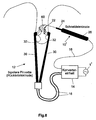
- FIG. 8 Finally, an application for the medical device arrangement described above is shown, specifically on the example of shortening an uvula.
- the gripping instrument 12 engages the uvula.
- the gripping instrument 12 is, as in FIG. 2 represented, almost monopolar connected to the converter unit 14 and forms with its gripping surfaces 32 a neutral electrode.
- the cutting instrument 10 is connected, so that upon actuation of the corresponding pressure switch, an electrical connection between the corresponding pole of the converter unit 14 and the cutting electrode 22 of the cutting instrument 10 is given. It Then comes to the flow of electricity schematically illustrated by arrows 60 from the cutting electrode 22 to the gripping surfaces 32, wherein due to the field strength concentration, the cutting electrode 22 forms as an active electrode and there is a spark discharge between the tip of the cutting electrode 22 and the body tissue to be separated.
- the converter unit 14 is connected all the time to the symbolically represented generator 1 ', which has a control unit which effects a switching off of the current in the event of a short circuit or when a maximum impedance limit value is exceeded.
- the gripping instrument used may also be formed according to the second embodiment described above as a unipolar gripping instrument, in which both gripping surfaces 32 are connected to a common electrical connection.
- One method of using the described medical device assembly is to first of all assemble the device, as exemplified in FIG. 8 represented, compiled. The doctor then next attacks the tissue part to be removed with the gripping instrument 12. Since the gripping instrument 12 attaches to the tissue part to be removed as a counterelectrode, there is a flow of current substantially only in the tissue part to be removed, so that potential burns due to poor electrical contact for example, between the gripping instrument 12 and the tissue part to be removed are unproblematic.
- the doctor guides the cutting instrument 10, and more precisely the cutting electrode 22, into the region of the intended tissue section. He can by pressing the corresponding pressure switch, the electrical connection between the cutting electrode 22 and the corresponding pole of the converter unit 14 produce, so that it comes with sufficient approach of the cutting electrode 22 to the body tissue to a spark gap between the cutting electrode 22 and body tissue through which the body tissue is separated , Of the corresponding current flows between the cutting electrode through the body tissue part to be separated to the gripping surfaces 32 of the gripping instrument which act as a neutral electrode because of their larger surface area. During this operation, the doctor holds the body tissue part to be removed with the gripping instrument 12 in order to be able to remove it after complete separation from the remaining body tissue with the aid of the gripping instrument 12. This concludes the electrotomy.
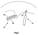
- FIG. 9 It is shown how the previously described medical device arrangement, for example for incisions in a soft palate, can be used.
- the uvula is pulled with the gripping instrument 12 'in one direction (in FIG. 9 to the left) and simultaneously with the cutting instrument 10 ', an incision is made. Due to the pull with the gripping instrument 12 ', the incision opens as in FIG. 9 shown.
- a uvula (uvulapalatopharyngoplasty, UPPP), which is shown by way of example, is also possible, for example, for the reduction of a soft palate also for the treatment of rachopathy.
- Other fields of application are also conceivable. Such other fields of application include the removal or reduction of the tonsils.
- the medical device assembly can also be used in dermatology, for example, for wart treatment.
- a wart can be grasped with a grasping instrument and then with a cutting instrument such as a wire loop as in FIG FIG. 1 shown, equipped, peeling apart from the remaining tissue.
Claims (24)
- Appareil médical pour la coupe de tissus corporels au moyen de l'électrotomie, comportant- un générateur (1) pour un courant alternatif haute fréquence qui peut être délivré par l'intermédiaire d'un pôle et d'un pôle opposé, chacun des pôles étant respectivement connecté à au moins une borne de sortie (2) du générateur (1) et le générateur étant réalisé pour produire une basse tension de sortie, appliquée en particulier à des fins de coagulation des tissus,- un bloc convertisseur (14),- un instrument de préhension (12) comportant deux bras de préhension (30) qui présentent chacun au moins une surface de préhension (32) et sont reliés mécaniquement l'un à l'autre de telle manière que les surfaces de préhension (32) peuvent se déplacer l'une vers l'autre, et- un instrument de coupe (10) qui présente une poignée (26) et une électrode de coupe (22),le bloc convertisseur (14) étant monté entre le générateur et l'instrument de préhension (12) ainsi que l'instrument de coupe (10) et étant raccordé côté générateur en tant qu'unité séparée à la borne de sortie (2) du générateur (1) connectée au pôle et au pôle opposé du générateur (1) et étant connecté côté sortie à l'instrument de préhension (12) d'une part et à l'instrument de coupe (10) d'autre part de telle manière qu'à un moment donné, les deux surfaces de préhension (32) de l'instrument de préhension (12) présentent un premier potentiel commun et l'électrode de coupe (22) présente un deuxième potentiel, de sorte que lors du fonctionnement de l'appareil médical, un courant alternatif haute fréquence circule entre l'instrument de préhension (12) et l'instrument de coupe (10), caractérisé en ce que le bloc convertisseur présente un transformateur haute fréquence dans lequel le rapport entre le nombre de spires (n2) de l'enroulement secondaire (44) et le nombre de spires (n1) de l'enroulement primaire (42) est n2 > n1, de sorte qu'en fonctionnement, le transformateur haute fréquence (40) transforme une basse tension de sortie du générateur en hautes tensions de sortie qui permettent en particulier l'allumage d'une étincelle d'une électrode de coupe et ainsi le sectionnement de tissus biologiques.
- Appareil médical selon la revendication 1, caractérisé en ce que le bloc convertisseur (14) présente un condensateur (50, 52) placé respectivement entre l'enroulement secondaire (44) et la première borne (46) d'une part et entre l'enroulement secondaire (44) et la deuxième borne (48) d'autre part.
- Appareil médical selon la revendication 2, caractérisé en ce que les condensateurs (50, 52) sont disposés pour être remplaçables à des fins d'adaptation à l'impédance.
- Appareil médical selon une des revendications 1 à 3, caractérisé en ce que la deuxième borne présente deux bornes montées en parallèle (48) pour l'instrument de préhension.
- Appareil médical selon une des revendications 1 à 4, caractérisé en ce que la tension de sortie du générateur (1) est de 80 V et la tension de sortie au niveau du bloc convertisseur (14) est de 200 V.
- Appareil médical selon une des revendications 1 à 5, caractérisé en ce que l'instrument de préhension (12) est un instrument bipolaire, sur lequel les surfaces de préhension (32) sont chacune réalisées pour être au moins partiellement électroconductrices, et sont chacune connectées l'une à l'autre individuellement par l'intermédiaire d'une borne électrique destinée à une ligne d'alimentation électrique (16) et connectée à la surface de préhension concernée, ou par l'intermédiaire d'une borne commune destinée à une ligne d'alimentation électrique (16) de telle manière que les deux surfaces de préhension sont montées électriquement en parallèle.
- Appareil médical selon une des revendications 1 à 6, caractérisé en ce que d'une part l'instrument de coupe (10) et d'autre part l'instrument de préhension (12) sont raccordés au bloc convertisseur (14) par l'intermédiaire des lignes d'alimentation électriques (16) correspondantes et en ce que le bloc convertisseur (14) présente côté entrée un câble (18) auquel est raccordé une prise mâle (20) pour le raccordement du bloc convertisseur (14) au générateur (1).
- Appareil médical selon une des revendications 1 à 7, l'instrument de préhension (12) pouvant adopter au choix un état ouvert ou un état fermé, chaque surface de préhension (32) étant réalisée pour être au moins partiellement électroconductrice, chacune étant isolée électriquement de l'autre surface de préhension (32) et chacune étant connectée individuellement à une borne destinée à une ligne d'alimentation électrique, caractérisé en ce que les deux lignes d'alimentation électriques sont connectées fixement par l'intermédiaire d'une jonction à une ligne d'alimentation électrique alimentant un instrument de coupe, et en ce que les deux lignes d'alimentation sont connectées par l'intermédiaire de la jonction à une ligne d'alimentation commune pour le raccordement à un générateur ou un ensemble convertisseur.
- Appareil médical selon une des revendications 1 à 7, l'instrument de préhension (12) pouvant adopter au choix un état ouvert ou un état fermé, les surfaces de préhension (32) étant réalisées pour être au moins partiellement électroconductrices, et étant connectées à une borne commune destinée à une ligne d'alimentation électrique, caractérisé en ce que la ligne d'alimentation électrique est connectée fixement par l'intermédiaire d'une jonction à une ligne d'alimentation électrique alimentant un instrument de coupe, et en ce que les deux lignes sont connectées par l'intermédiaire de la jonction à une ligne d'alimentation commune pour le raccordement à un générateur ou à un bloc convertisseur.
- Appareil médical selon la revendication 8 ou 9, caractérisé en ce que la surface de préhension (32) présente une structure de surface comportant des saillies qui permettent une prise sûre de fragments de corps.
- Appareil médical selon la revendication 10, caractérisé en ce que les saillies ont la forme de dents de prise (34).
- Appareil médical selon une des revendications 8 à 11, caractérisé en ce que chaque surface de préhension (32) est partie intégrante d'un insert de préhension remplaçable destiné à être fixé à l'instrument de préhension (12).
- Appareil médical selon la revendication 12, caractérisé en ce que chaque insert de préhension est destiné à être fixé sur une extrémité distale d'un bras de préhension (30).
- Appareil médical selon la revendication 12 ou 13, caractérisé en ce que l'insert de préhension est constitué d'acier inoxydable.
- Appareil médical selon une des revendications 8 à 14, caractérisé en ce que l'instrument de préhension (12) est réalisé à la manière d'une pincette.
- Appareil médical selon une des revendications 8 à 14, caractérisé en ce que l'instrument de préhension (12) est réalisé à la manière d'une pince de prise.
- Appareil médical selon une des revendications 8 à 16, caractérisé en ce que l'instrument de préhension (12) adopte automatiquement l'état ouvert sans que soit exercée une force extérieure.
- Appareil médical selon une des revendications 8 à 16, caractérisé en ce que l'instrument de préhension (12), une fois mis à l'état fermé, conserve cet état ou doit être verrouillé à l'état fermé.
- Appareil médical selon une des revendications 8 à 16, caractérisé en ce qu'à l'état fermé, l'instrument de préhension (12) est précontraint par ressort et doit être ouvert à l'encontre d'une force de ressort.
- Appareil médical selon une des revendications 1 à 7, sur lequel la poignée (26) de l'instrument de coupe présente une surface de préhension (32) qui est isolée par rapport à l'électrode de coupe (22) et en ce que la poignée (26) présente une borne destinée à une ligne d'alimentation électrique qui est connectée électriquement à l'électrode de coupe (22), l'électrode de coupe (22) étant disposée à une extrémité distale d'une tige d'électrode (24) et étant connectée à la poignée (26) par l'intermédiaire de la tige d'électrode (24), caractérisé en ce que la ligne d'alimentation électrique est connectée fixement par l'intermédiaire d'une jonction à une ligne d'alimentation électrique alimentant l'instrument de préhension et en ce que les deux lignes d'alimentation sont connectées par l'intermédiaire de la jonction à une ligne d'alimentation commune pour le raccordement à un générateur ou à un ensemble convertisseur.
- Appareil médical selon la revendication 20, caractérisé en ce que l'électrode de coupe (22) est pointue.
- Appareil médical selon la revendication 20 ou 21, caractérisé en ce que l'électrode de coupe est réalisée sous la forme d'une boucle de fil.
- Appareil médical selon une des revendications 20 à 22, caractérisé en ce que l'électrode de coupe ou l'électrode de coupe et la tige d'électrode sont connectées de manière interchangeable à l'autre instrument de coupe, en particulier la poignée.
- Appareil médical selon une des revendications 20 à 23, caractérisé par un interrupteur à poussoir disposé sur la poignée et actionné par un doigt, et avec lequel une connexion électrique alimentant l'électrode de coupe peut être au choix établie ou interrompue.
Applications Claiming Priority (4)
| Application Number | Priority Date | Filing Date | Title |
|---|---|---|---|
| DE2003151818 DE10351818A1 (de) | 2003-10-29 | 2003-10-29 | Medizingerät für die Elektrotomie |
| DE10351818 | 2003-10-29 | ||
| DE10361142 | 2003-12-16 | ||
| DE10361142 | 2003-12-16 |
Publications (3)
| Publication Number | Publication Date |
|---|---|
| EP1527743A2 EP1527743A2 (fr) | 2005-05-04 |
| EP1527743A3 EP1527743A3 (fr) | 2005-07-20 |
| EP1527743B1 true EP1527743B1 (fr) | 2009-07-29 |
Family
ID=34424347
Family Applications (1)
| Application Number | Title | Priority Date | Filing Date |
|---|---|---|---|
| EP04090402A Not-in-force EP1527743B1 (fr) | 2003-10-29 | 2004-10-21 | Dispositif médical pour électrotomie |
Country Status (7)
| Country | Link |
|---|---|
| US (1) | US20050096681A1 (fr) |
| EP (1) | EP1527743B1 (fr) |
| JP (1) | JP4603854B2 (fr) |
| KR (1) | KR20050040761A (fr) |
| CN (1) | CN100455273C (fr) |
| AT (1) | ATE437611T1 (fr) |
| DE (1) | DE502004009815D1 (fr) |
Families Citing this family (69)
| Publication number | Priority date | Publication date | Assignee | Title |
|---|---|---|---|---|
| US6478793B1 (en) * | 1999-06-11 | 2002-11-12 | Sherwood Services Ag | Ablation treatment of bone metastases |
| US20050004559A1 (en) | 2003-06-03 | 2005-01-06 | Senorx, Inc. | Universal medical device control console |
| US6620157B1 (en) | 2000-12-28 | 2003-09-16 | Senorx, Inc. | High frequency power source |
| US8133218B2 (en) * | 2000-12-28 | 2012-03-13 | Senorx, Inc. | Electrosurgical medical system and method |
| US7393354B2 (en) * | 2002-07-25 | 2008-07-01 | Sherwood Services Ag | Electrosurgical pencil with drag sensing capability |
| US7244257B2 (en) | 2002-11-05 | 2007-07-17 | Sherwood Services Ag | Electrosurgical pencil having a single button variable control |
| WO2004073753A2 (fr) * | 2003-02-20 | 2004-09-02 | Sherwood Services Ag | Detecteur de mouvement destine a commander une sortie electrochirurgicale |
| US7503917B2 (en) | 2003-11-20 | 2009-03-17 | Covidien Ag | Electrosurgical pencil with improved controls |
| US7156842B2 (en) * | 2003-11-20 | 2007-01-02 | Sherwood Services Ag | Electrosurgical pencil with improved controls |
| US7879033B2 (en) * | 2003-11-20 | 2011-02-01 | Covidien Ag | Electrosurgical pencil with advanced ES controls |
| US7776035B2 (en) * | 2004-10-08 | 2010-08-17 | Covidien Ag | Cool-tip combined electrode introducer |
| US7553309B2 (en) * | 2004-10-08 | 2009-06-30 | Covidien Ag | Electrosurgical system employing multiple electrodes and method thereof |
| US7282049B2 (en) * | 2004-10-08 | 2007-10-16 | Sherwood Services Ag | Electrosurgical system employing multiple electrodes and method thereof |
| US8795195B2 (en) | 2004-11-29 | 2014-08-05 | Senorx, Inc. | Graphical user interface for tissue biopsy system |
| US7500974B2 (en) | 2005-06-28 | 2009-03-10 | Covidien Ag | Electrode with rotatably deployable sheath |
| US7828794B2 (en) | 2005-08-25 | 2010-11-09 | Covidien Ag | Handheld electrosurgical apparatus for controlling operating room equipment |
| US20070066971A1 (en) * | 2005-09-21 | 2007-03-22 | Podhajsky Ronald J | Method and system for treating pain during an electrosurgical procedure |
| US7879031B2 (en) * | 2005-09-27 | 2011-02-01 | Covidien Ag | Cooled RF ablation needle |
| US20070078454A1 (en) * | 2005-09-30 | 2007-04-05 | Mcpherson James W | System and method for creating lesions using bipolar electrodes |
| US20070078453A1 (en) * | 2005-10-04 | 2007-04-05 | Johnson Kristin D | System and method for performing cardiac ablation |
| JP2007135914A (ja) * | 2005-11-18 | 2007-06-07 | Olympus Medical Systems Corp | 電気手術装置 |
| US8382748B2 (en) * | 2006-01-03 | 2013-02-26 | Donald J. Geisel | High efficiency, precision electrosurgical apparatus and method |
| US20070258838A1 (en) * | 2006-05-03 | 2007-11-08 | Sherwood Services Ag | Peristaltic cooling pump system |
| US20070260240A1 (en) * | 2006-05-05 | 2007-11-08 | Sherwood Services Ag | Soft tissue RF transection and resection device |
| CA2662789C (fr) | 2006-06-05 | 2019-07-02 | Senorx, Inc. | Systeme de biopsie a imagerie ultrasonore integree |
| DE102006027150A1 (de) * | 2006-06-08 | 2007-12-13 | Celon Ag Medical Instruments | Vorrichtung zum Schneiden und Koagulieren von Gewebe |
| US7763018B2 (en) * | 2006-07-28 | 2010-07-27 | Covidien Ag | Cool-tip thermocouple including two-piece hub |
| US8211099B2 (en) | 2007-01-31 | 2012-07-03 | Tyco Healthcare Group Lp | Thermal feedback systems and methods of using the same |
| US9486269B2 (en) * | 2007-06-22 | 2016-11-08 | Covidien Lp | Electrosurgical systems and cartridges for use therewith |
| CA2693225A1 (fr) * | 2007-07-13 | 2009-01-22 | Yigal Gat | Methodes et appareils pour le traitement vasculaire et le traitement de la prostate |
| US20090018486A1 (en) * | 2007-07-13 | 2009-01-15 | Menachem Goren | Diagnosis and treatment of vericocele and prostate disorders |
| US20100204639A1 (en) * | 2007-07-13 | 2010-08-12 | Yigal Gat | Diagnosis and treatment of varicocele and prostate disorders |
| US8506565B2 (en) | 2007-08-23 | 2013-08-13 | Covidien Lp | Electrosurgical device with LED adapter |
| US8181995B2 (en) * | 2007-09-07 | 2012-05-22 | Tyco Healthcare Group Lp | Cool tip junction |
| US8396806B2 (en) | 2007-10-30 | 2013-03-12 | Red Hat, Inc. | End user license agreements associated with messages |
| US8292880B2 (en) | 2007-11-27 | 2012-10-23 | Vivant Medical, Inc. | Targeted cooling of deployable microwave antenna |
| US8235987B2 (en) | 2007-12-05 | 2012-08-07 | Tyco Healthcare Group Lp | Thermal penetration and arc length controllable electrosurgical pencil |
| US8636733B2 (en) | 2008-03-31 | 2014-01-28 | Covidien Lp | Electrosurgical pencil including improved controls |
| US8663218B2 (en) | 2008-03-31 | 2014-03-04 | Covidien Lp | Electrosurgical pencil including improved controls |
| US8597292B2 (en) | 2008-03-31 | 2013-12-03 | Covidien Lp | Electrosurgical pencil including improved controls |
| EP2364662B1 (fr) | 2008-03-31 | 2013-10-23 | Applied Medical Resources Corporation | Système électrochirurgical avec une mécanisme de commutation |
| US8162937B2 (en) | 2008-06-27 | 2012-04-24 | Tyco Healthcare Group Lp | High volume fluid seal for electrosurgical handpiece |
| US8608739B2 (en) * | 2008-07-22 | 2013-12-17 | Covidien Lp | Electrosurgical devices, systems and methods of using the same |
| PL2337516T3 (pl) * | 2008-10-01 | 2016-06-30 | Erbe Elektromedizin | Elektrochirurgiczny generator HF |
| US20100130972A1 (en) * | 2008-11-21 | 2010-05-27 | Frantz Medical Development, Ltd. | Electrical skin treatment device and method |
| US8231620B2 (en) | 2009-02-10 | 2012-07-31 | Tyco Healthcare Group Lp | Extension cutting blade |
| US20100256735A1 (en) * | 2009-04-03 | 2010-10-07 | Board Of Regents, The University Of Texas System | Intraluminal stent with seam |
| DE102009018521A1 (de) | 2009-04-24 | 2010-10-28 | Olympus Winter & Ibe Gmbh | Hysterektomiegerät mit Uterusmanipulator |
| US20110060335A1 (en) * | 2009-09-10 | 2011-03-10 | Tyco Healthcare Group Lp | Apparatus for Tissue Fusion and Method of Use |
| DE102009040899A1 (de) | 2009-09-11 | 2011-03-17 | Celon Ag Medical Instruments | Elektrochirurgisches Greifinstrument |
| EP3332723B1 (fr) | 2010-10-01 | 2022-02-16 | Applied Medical Resources Corporation | Instruments électrochirurgicaux et connexions à ceux-ci |
| EP2540242B1 (fr) * | 2011-06-28 | 2014-05-21 | Lina Medical ApS | Instrument électrochirurgical et dispositif pour ledit instrument |
| DE102012203943A1 (de) | 2012-03-14 | 2013-09-19 | Olympus Winter & Ibe Gmbh | HF Pinzette mit aktivierbaren Zähnen |
| US9089337B2 (en) * | 2013-11-07 | 2015-07-28 | Gyrus Acmi, Inc. | Electrosurgical system having grasper and snare with switchable electrode |
| EP3142583B1 (fr) | 2014-05-16 | 2023-04-12 | Applied Medical Resources Corporation | Système électrochirurgical |
| WO2015184446A2 (fr) | 2014-05-30 | 2015-12-03 | Applied Medical Resources Corporation | Systèmes électrochirurgicaux de scellement et de dissection |
| KR102560348B1 (ko) | 2014-11-26 | 2023-07-28 | 데비코어 메디컬 프로덕츠, 인코포레이티드 | 생검 장치의 그래픽 사용자 인터페이스 |
| EP3236870B1 (fr) | 2014-12-23 | 2019-11-06 | Applied Medical Resources Corporation | Dispositif de fermeture hermétique et de division électrochirurgical bipolaire |
| USD748259S1 (en) | 2014-12-29 | 2016-01-26 | Applied Medical Resources Corporation | Electrosurgical instrument |
| KR101833976B1 (ko) * | 2016-04-07 | 2018-03-08 | 주식회사 메디셀러 | 고주파 치료기 |
| US10610291B2 (en) | 2016-09-26 | 2020-04-07 | Gyrus Acmi, Inc. | Reconfigurable instrument |
| DE102017109638A1 (de) * | 2017-05-04 | 2018-11-08 | Olympus Winter & Ibe Gmbh | Generator für die Abgabe hochfrequenten Wechselstroms an ein Medizininstrument |
| US11253308B2 (en) * | 2017-05-12 | 2022-02-22 | Covidien Lp | Colpotomy systems, devices, and methods with rotational cutting |
| KR102446776B1 (ko) * | 2017-12-19 | 2022-09-23 | 인튜어티브 서지컬 오퍼레이션즈 인코포레이티드 | 동시적인 전기수술 봉합 및 절단 |
| GB2570297B (en) | 2018-01-17 | 2022-10-12 | Gyrus Medical Ltd | Bipolar electrosurgical instruments |
| WO2020051369A1 (fr) | 2018-09-05 | 2020-03-12 | Applied Medical Resources Corporation | Système de commande de générateur électrochirurgical |
| CA3120182A1 (fr) | 2018-11-16 | 2020-05-22 | Applied Medical Resources Corporation | Systeme electrochirurgical |
| US11564732B2 (en) | 2019-12-05 | 2023-01-31 | Covidien Lp | Tensioning mechanism for bipolar pencil |
| US20230380890A1 (en) * | 2022-05-26 | 2023-11-30 | Biosense Webster (Israel) Ltd. | Transseptal tissue puncture apparatuses, systems, and methods |
Citations (1)
| Publication number | Priority date | Publication date | Assignee | Title |
|---|---|---|---|---|
| US5633578A (en) * | 1991-06-07 | 1997-05-27 | Hemostatic Surgery Corporation | Electrosurgical generator adaptors |
Family Cites Families (30)
| Publication number | Priority date | Publication date | Assignee | Title |
|---|---|---|---|---|
| US4000743A (en) * | 1975-07-09 | 1977-01-04 | Kenneth Weaver | Uterine anteverter |
| GB8401887D0 (en) * | 1984-01-25 | 1984-02-29 | Matburn Holdings Ltd | Electrosurgical unit |
| DE3447156A1 (de) * | 1984-12-22 | 1986-07-03 | Hermann 7803 Gundelfingen Sutter | Bipolares greifinstrument insbesondere fuer die allgemeinchirurgie |
| DD241550A1 (de) * | 1985-10-04 | 1986-12-17 | Transform Roentgen Matern Veb | Hochfrequenzchirugiegeraet |
| JPH07106192B2 (ja) * | 1989-08-11 | 1995-11-15 | 松下電器産業株式会社 | セントラル形掃除機 |
| US5078716A (en) * | 1990-05-11 | 1992-01-07 | Doll Larry F | Electrosurgical apparatus for resecting abnormal protruding growth |
| US5190541A (en) * | 1990-10-17 | 1993-03-02 | Boston Scientific Corporation | Surgical instrument and method |
| US5160334A (en) * | 1991-04-30 | 1992-11-03 | Utah Medical Products, Inc. | Electrosurgical generator and suction apparatus |
| WO1994020025A1 (fr) * | 1993-03-04 | 1994-09-15 | Microsurge, Inc. | Instrument chirurgical |
| US5417697A (en) * | 1993-07-07 | 1995-05-23 | Wilk; Peter J. | Polyp retrieval assembly with cauterization loop and suction web |
| US5843021A (en) * | 1994-05-09 | 1998-12-01 | Somnus Medical Technologies, Inc. | Cell necrosis apparatus |
| US5562503A (en) * | 1994-12-05 | 1996-10-08 | Ellman; Alan G. | Bipolar adaptor for electrosurgical instrument |
| US5766165A (en) * | 1995-09-22 | 1998-06-16 | Gentelia; John S. | Return path monitoring system |
| JPH09135843A (ja) * | 1995-11-17 | 1997-05-27 | Olympus Optical Co Ltd | 外科手術装置 |
| US5683388A (en) * | 1996-01-11 | 1997-11-04 | Symbiosis Corporation | Endoscopic bipolar multiple sample bioptome |
| DE19706269A1 (de) * | 1996-03-21 | 1997-09-25 | Valleylab Inc | Instrument zur gasangereicherten Elektrochirurgie |
| US5871482A (en) * | 1996-06-18 | 1999-02-16 | Zhou; Jingren | Bionic cervix uteri dilator |
| JP3668573B2 (ja) * | 1996-11-22 | 2005-07-06 | ジョンソン・エンド・ジョンソン株式会社 | 双極電気凝固及び切開用ピンセツト |
| US6113596A (en) * | 1996-12-30 | 2000-09-05 | Enable Medical Corporation | Combination monopolar-bipolar electrosurgical instrument system, instrument and cable |
| US5964758A (en) * | 1997-09-18 | 1999-10-12 | Dresden; Scott | Laparoscopic electrosurgical instrument |
| DE19757720A1 (de) * | 1997-12-23 | 1999-06-24 | Sulzer Osypka Gmbh | Verfahren zum Betrieb einer Hochfrequenz-Ablationsvorrichtung und Vorrichtung für die Hochfrequenz-Gewebe-Ablation |
| US6679882B1 (en) * | 1998-06-22 | 2004-01-20 | Lina Medical Aps | Electrosurgical device for coagulating and for making incisions, a method of severing blood vessels and a method of coagulating and for making incisions in or severing tissue |
| US6190385B1 (en) * | 1998-12-11 | 2001-02-20 | Ethicon, Inc. | Cable for bipolar electro-surgical instrument |
| US6190386B1 (en) * | 1999-03-09 | 2001-02-20 | Everest Medical Corporation | Electrosurgical forceps with needle electrodes |
| JP2001029353A (ja) * | 1999-07-21 | 2001-02-06 | Olympus Optical Co Ltd | 超音波処置装置 |
| DE19957919A1 (de) * | 1999-11-25 | 2001-06-21 | Ethicon Gmbh | Schaltvorrichtung für elektrochirurgische Geräte |
| DE10042096C1 (de) * | 2000-08-26 | 2002-01-24 | Winter & Ibe Olympus | Elektrode für ein urologisches Resektoskop |
| DE10061278B4 (de) * | 2000-12-08 | 2004-09-16 | GFD-Gesellschaft für Diamantprodukte mbH | Instrument für chirurgische Zwecke |
| DE10253819A1 (de) * | 2002-11-18 | 2004-07-01 | Storz Endoskop Produktions Gmbh | Elektrochirurgische Vorrichtung sowie Verfahren zum Betreiben derselben |
| CN2580913Y (zh) * | 2002-11-30 | 2003-10-22 | 樊学斌 | 软腭电切器 |
-
2004
- 2004-10-21 DE DE502004009815T patent/DE502004009815D1/de active Active
- 2004-10-21 AT AT04090402T patent/ATE437611T1/de not_active IP Right Cessation
- 2004-10-21 EP EP04090402A patent/EP1527743B1/fr not_active Not-in-force
- 2004-10-26 US US10/973,893 patent/US20050096681A1/en not_active Abandoned
- 2004-10-27 JP JP2004312999A patent/JP4603854B2/ja not_active Expired - Fee Related
- 2004-10-27 KR KR1020040086197A patent/KR20050040761A/ko not_active Application Discontinuation
- 2004-10-29 CN CNB2004100867446A patent/CN100455273C/zh not_active Expired - Fee Related
Patent Citations (1)
| Publication number | Priority date | Publication date | Assignee | Title |
|---|---|---|---|---|
| US5633578A (en) * | 1991-06-07 | 1997-05-27 | Hemostatic Surgery Corporation | Electrosurgical generator adaptors |
Also Published As
| Publication number | Publication date |
|---|---|
| CN1611192A (zh) | 2005-05-04 |
| US20050096681A1 (en) | 2005-05-05 |
| JP2005131403A (ja) | 2005-05-26 |
| CN100455273C (zh) | 2009-01-28 |
| KR20050040761A (ko) | 2005-05-03 |
| EP1527743A3 (fr) | 2005-07-20 |
| JP4603854B2 (ja) | 2010-12-22 |
| EP1527743A2 (fr) | 2005-05-04 |
| ATE437611T1 (de) | 2009-08-15 |
| DE502004009815D1 (de) | 2009-09-10 |
Similar Documents
| Publication | Publication Date | Title |
|---|---|---|
| EP1527743B1 (fr) | Dispositif médical pour électrotomie | |
| DE69833505T2 (de) | Bipolares elektrochirurgisches instrument zum verschliessen von gefässen | |
| EP2029039B1 (fr) | Dispositif de découpage et de coagulation de tissus | |
| EP0871405B1 (fr) | Instrument chirurgical bipolaire a haute frequence | |
| EP1399079B1 (fr) | Dispositif electrochirurgical | |
| DE2540968C2 (de) | Einrichtung zum Einschalten des Koagulationsstroms einer bipolaren Koagulationspinzette | |
| DE3510586C2 (fr) | ||
| DE69831693T2 (de) | Ein elektrochirurgisches gerät zur koagulation und zum schneiden | |
| DE69826957T2 (de) | Kombiniertes bipolares Scheren- und Greifinstrument | |
| DE3423356C2 (de) | Elektrochirurgisches Hochfrequenz-Schneidinstrument | |
| DE10253819A1 (de) | Elektrochirurgische Vorrichtung sowie Verfahren zum Betreiben derselben | |
| DE102009041329A1 (de) | Kombiniertes Ultraschall- und HF Chirurgisches System | |
| DE102010031569A1 (de) | Elektrochirurgisches Instrument | |
| DE19751108A1 (de) | Elektrochirurgisches Operationswerkzeug | |
| EP0495140A1 (fr) | Appareil pour électrochirurgie à haute fréquence | |
| EP2044900A2 (fr) | Instrument d'électrochirurgie | |
| DE2513868A1 (de) | Elektrische vorrichtung zum behandeln von erkranktem gewebe durch hindurchleiten eines hochfrequenten stroms | |
| DE112012001600T5 (de) | Elektrochirurgischer Generator | |
| EP3132765B1 (fr) | Instrument de coagulation et de dissection a commande amelioree | |
| DE10351818A1 (de) | Medizingerät für die Elektrotomie | |
| DE102019100653A1 (de) | Bipolare Elekrochirugische Instrumente | |
| EP2366353A1 (fr) | Ciseaux électrochirurgicaux bipolaires pour la dissection et la coagulation | |
| EP2298204A1 (fr) | Instrument médical pour l'électrochirurgie bipolaire | |
| DE2019891C3 (de) | Vorrichtung zur Koagulation anatomischer Gebilde mittels eines Hochfrequenzstroms | |
| DE102009040899A1 (de) | Elektrochirurgisches Greifinstrument |
Legal Events
| Date | Code | Title | Description |
|---|---|---|---|
| PUAI | Public reference made under article 153(3) epc to a published international application that has entered the european phase |
Free format text: ORIGINAL CODE: 0009012 |
|
| AK | Designated contracting states |
Kind code of ref document: A2 Designated state(s): AT BE BG CH CY CZ DE DK EE ES FI FR GB GR HU IE IT LI LU MC NL PL PT RO SE SI SK TR |
|
| AX | Request for extension of the european patent |
Extension state: AL HR LT LV MK |
|
| PUAL | Search report despatched |
Free format text: ORIGINAL CODE: 0009013 |
|
| AK | Designated contracting states |
Kind code of ref document: A3 Designated state(s): AT BE BG CH CY CZ DE DK EE ES FI FR GB GR HU IE IT LI LU MC NL PL PT RO SE SI SK TR |
|
| AX | Request for extension of the european patent |
Extension state: AL HR LT LV MK |
|
| 17P | Request for examination filed |
Effective date: 20060120 |
|
| AKX | Designation fees paid |
Designated state(s): AT BE BG CH CY CZ DE DK EE ES FI FR GB GR HU IE IT LI LU MC NL PL PT RO SE SI SK TR |
|
| 17Q | First examination report despatched |
Effective date: 20071002 |
|
| GRAP | Despatch of communication of intention to grant a patent |
Free format text: ORIGINAL CODE: EPIDOSNIGR1 |
|
| RIN1 | Information on inventor provided before grant (corrected) |
Inventor name: STEIN, THOMAS Inventor name: ROGGAN, ANDRE Inventor name: DESINGER, KAI |
|
| GRAS | Grant fee paid |
Free format text: ORIGINAL CODE: EPIDOSNIGR3 |
|
| GRAA | (expected) grant |
Free format text: ORIGINAL CODE: 0009210 |
|
| AK | Designated contracting states |
Kind code of ref document: B1 Designated state(s): AT BE BG CH CY CZ DE DK EE ES FI FR GB GR HU IE IT LI LU MC NL PL PT RO SE SI SK TR |
|
| REG | Reference to a national code |
Ref country code: GB Ref legal event code: FG4D Free format text: NOT ENGLISH |
|
| REG | Reference to a national code |
Ref country code: CH Ref legal event code: EP |
|
| REG | Reference to a national code |
Ref country code: IE Ref legal event code: FG4D |
|
| REF | Corresponds to: |
Ref document number: 502004009815 Country of ref document: DE Date of ref document: 20090910 Kind code of ref document: P |
|
| NLV1 | Nl: lapsed or annulled due to failure to fulfill the requirements of art. 29p and 29m of the patents act | ||
| PG25 | Lapsed in a contracting state [announced via postgrant information from national office to epo] |
Ref country code: FI Free format text: LAPSE BECAUSE OF FAILURE TO SUBMIT A TRANSLATION OF THE DESCRIPTION OR TO PAY THE FEE WITHIN THE PRESCRIBED TIME-LIMIT Effective date: 20090729 Ref country code: SE Free format text: LAPSE BECAUSE OF FAILURE TO SUBMIT A TRANSLATION OF THE DESCRIPTION OR TO PAY THE FEE WITHIN THE PRESCRIBED TIME-LIMIT Effective date: 20090729 Ref country code: ES Free format text: LAPSE BECAUSE OF FAILURE TO SUBMIT A TRANSLATION OF THE DESCRIPTION OR TO PAY THE FEE WITHIN THE PRESCRIBED TIME-LIMIT Effective date: 20091109 |
|
| PG25 | Lapsed in a contracting state [announced via postgrant information from national office to epo] |
Ref country code: SI Free format text: LAPSE BECAUSE OF FAILURE TO SUBMIT A TRANSLATION OF THE DESCRIPTION OR TO PAY THE FEE WITHIN THE PRESCRIBED TIME-LIMIT Effective date: 20090729 Ref country code: NL Free format text: LAPSE BECAUSE OF FAILURE TO SUBMIT A TRANSLATION OF THE DESCRIPTION OR TO PAY THE FEE WITHIN THE PRESCRIBED TIME-LIMIT Effective date: 20090729 Ref country code: PL Free format text: LAPSE BECAUSE OF FAILURE TO SUBMIT A TRANSLATION OF THE DESCRIPTION OR TO PAY THE FEE WITHIN THE PRESCRIBED TIME-LIMIT Effective date: 20090729 |
|
| REG | Reference to a national code |
Ref country code: IE Ref legal event code: FD4D |
|
| PG25 | Lapsed in a contracting state [announced via postgrant information from national office to epo] |
Ref country code: BG Free format text: LAPSE BECAUSE OF FAILURE TO SUBMIT A TRANSLATION OF THE DESCRIPTION OR TO PAY THE FEE WITHIN THE PRESCRIBED TIME-LIMIT Effective date: 20091029 Ref country code: PT Free format text: LAPSE BECAUSE OF FAILURE TO SUBMIT A TRANSLATION OF THE DESCRIPTION OR TO PAY THE FEE WITHIN THE PRESCRIBED TIME-LIMIT Effective date: 20091129 |
|
| BERE | Be: lapsed |
Owner name: CELON A.G. MEDICAL INSTRUMENTS Effective date: 20091031 |
|
| PG25 | Lapsed in a contracting state [announced via postgrant information from national office to epo] |
Ref country code: RO Free format text: LAPSE BECAUSE OF FAILURE TO SUBMIT A TRANSLATION OF THE DESCRIPTION OR TO PAY THE FEE WITHIN THE PRESCRIBED TIME-LIMIT Effective date: 20090729 Ref country code: DK Free format text: LAPSE BECAUSE OF FAILURE TO SUBMIT A TRANSLATION OF THE DESCRIPTION OR TO PAY THE FEE WITHIN THE PRESCRIBED TIME-LIMIT Effective date: 20090729 Ref country code: IE Free format text: LAPSE BECAUSE OF FAILURE TO SUBMIT A TRANSLATION OF THE DESCRIPTION OR TO PAY THE FEE WITHIN THE PRESCRIBED TIME-LIMIT Effective date: 20090729 Ref country code: EE Free format text: LAPSE BECAUSE OF FAILURE TO SUBMIT A TRANSLATION OF THE DESCRIPTION OR TO PAY THE FEE WITHIN THE PRESCRIBED TIME-LIMIT Effective date: 20090729 Ref country code: CZ Free format text: LAPSE BECAUSE OF FAILURE TO SUBMIT A TRANSLATION OF THE DESCRIPTION OR TO PAY THE FEE WITHIN THE PRESCRIBED TIME-LIMIT Effective date: 20090729 |
|
| PG25 | Lapsed in a contracting state [announced via postgrant information from national office to epo] |
Ref country code: MC Free format text: LAPSE BECAUSE OF NON-PAYMENT OF DUE FEES Effective date: 20091031 Ref country code: SK Free format text: LAPSE BECAUSE OF FAILURE TO SUBMIT A TRANSLATION OF THE DESCRIPTION OR TO PAY THE FEE WITHIN THE PRESCRIBED TIME-LIMIT Effective date: 20090729 |
|
| REG | Reference to a national code |
Ref country code: CH Ref legal event code: PL |
|
| PLBE | No opposition filed within time limit |
Free format text: ORIGINAL CODE: 0009261 |
|
| STAA | Information on the status of an ep patent application or granted ep patent |
Free format text: STATUS: NO OPPOSITION FILED WITHIN TIME LIMIT |
|
| 26N | No opposition filed |
Effective date: 20100503 |
|
| PG25 | Lapsed in a contracting state [announced via postgrant information from national office to epo] |
Ref country code: LI Free format text: LAPSE BECAUSE OF NON-PAYMENT OF DUE FEES Effective date: 20091031 Ref country code: GR Free format text: LAPSE BECAUSE OF FAILURE TO SUBMIT A TRANSLATION OF THE DESCRIPTION OR TO PAY THE FEE WITHIN THE PRESCRIBED TIME-LIMIT Effective date: 20091030 Ref country code: BE Free format text: LAPSE BECAUSE OF NON-PAYMENT OF DUE FEES Effective date: 20091031 Ref country code: CH Free format text: LAPSE BECAUSE OF NON-PAYMENT OF DUE FEES Effective date: 20091031 |
|
| PG25 | Lapsed in a contracting state [announced via postgrant information from national office to epo] |
Ref country code: AT Free format text: LAPSE BECAUSE OF NON-PAYMENT OF DUE FEES Effective date: 20091021 |
|
| PG25 | Lapsed in a contracting state [announced via postgrant information from national office to epo] |
Ref country code: IT Free format text: LAPSE BECAUSE OF FAILURE TO SUBMIT A TRANSLATION OF THE DESCRIPTION OR TO PAY THE FEE WITHIN THE PRESCRIBED TIME-LIMIT Effective date: 20090729 |
|
| PG25 | Lapsed in a contracting state [announced via postgrant information from national office to epo] |
Ref country code: LU Free format text: LAPSE BECAUSE OF NON-PAYMENT OF DUE FEES Effective date: 20091021 |
|
| PG25 | Lapsed in a contracting state [announced via postgrant information from national office to epo] |
Ref country code: HU Free format text: LAPSE BECAUSE OF FAILURE TO SUBMIT A TRANSLATION OF THE DESCRIPTION OR TO PAY THE FEE WITHIN THE PRESCRIBED TIME-LIMIT Effective date: 20100130 |
|
| PG25 | Lapsed in a contracting state [announced via postgrant information from national office to epo] |
Ref country code: TR Free format text: LAPSE BECAUSE OF FAILURE TO SUBMIT A TRANSLATION OF THE DESCRIPTION OR TO PAY THE FEE WITHIN THE PRESCRIBED TIME-LIMIT Effective date: 20090729 |
|
| PG25 | Lapsed in a contracting state [announced via postgrant information from national office to epo] |
Ref country code: CY Free format text: LAPSE BECAUSE OF FAILURE TO SUBMIT A TRANSLATION OF THE DESCRIPTION OR TO PAY THE FEE WITHIN THE PRESCRIBED TIME-LIMIT Effective date: 20090729 |
|
| REG | Reference to a national code |
Ref country code: FR Ref legal event code: PLFP Year of fee payment: 12 |
|
| REG | Reference to a national code |
Ref country code: FR Ref legal event code: PLFP Year of fee payment: 13 |
|
| REG | Reference to a national code |
Ref country code: FR Ref legal event code: PLFP Year of fee payment: 14 |
|
| REG | Reference to a national code |
Ref country code: FR Ref legal event code: PLFP Year of fee payment: 15 |
|
| PGFP | Annual fee paid to national office [announced via postgrant information from national office to epo] |
Ref country code: DE Payment date: 20201022 Year of fee payment: 17 Ref country code: FR Payment date: 20201021 Year of fee payment: 17 Ref country code: GB Payment date: 20201022 Year of fee payment: 17 |
|
| REG | Reference to a national code |
Ref country code: DE Ref legal event code: R119 Ref document number: 502004009815 Country of ref document: DE |
|
| GBPC | Gb: european patent ceased through non-payment of renewal fee |
Effective date: 20211021 |
|
| PG25 | Lapsed in a contracting state [announced via postgrant information from national office to epo] |
Ref country code: GB Free format text: LAPSE BECAUSE OF NON-PAYMENT OF DUE FEES Effective date: 20211021 Ref country code: DE Free format text: LAPSE BECAUSE OF NON-PAYMENT OF DUE FEES Effective date: 20220503 |
|
| PG25 | Lapsed in a contracting state [announced via postgrant information from national office to epo] |
Ref country code: FR Free format text: LAPSE BECAUSE OF NON-PAYMENT OF DUE FEES Effective date: 20211031 |