EP1527501B1 - Steckerkupplung für elektrische Geräte und Ladegerät mit einer derartigen Steckerkupplung - Google Patents
Steckerkupplung für elektrische Geräte und Ladegerät mit einer derartigen Steckerkupplung Download PDFInfo
- Publication number
- EP1527501B1 EP1527501B1 EP03766063A EP03766063A EP1527501B1 EP 1527501 B1 EP1527501 B1 EP 1527501B1 EP 03766063 A EP03766063 A EP 03766063A EP 03766063 A EP03766063 A EP 03766063A EP 1527501 B1 EP1527501 B1 EP 1527501B1
- Authority
- EP
- European Patent Office
- Prior art keywords
- power plug
- plug
- guide web
- contact elements
- recess
- Prior art date
- Legal status (The legal status is an assumption and is not a legal conclusion. Google has not performed a legal analysis and makes no representation as to the accuracy of the status listed.)
- Expired - Lifetime
Links
- 230000008878 coupling Effects 0.000 title claims abstract description 51
- 238000010168 coupling process Methods 0.000 title claims abstract description 51
- 238000005859 coupling reaction Methods 0.000 title claims abstract description 51
- 230000033001 locomotion Effects 0.000 abstract description 15
- 239000000243 solution Substances 0.000 description 5
- 230000005540 biological transmission Effects 0.000 description 3
- 238000010276 construction Methods 0.000 description 3
- 239000007822 coupling agent Substances 0.000 description 2
- 238000006073 displacement reaction Methods 0.000 description 2
- 238000004519 manufacturing process Methods 0.000 description 2
- 238000005452 bending Methods 0.000 description 1
- 239000004020 conductor Substances 0.000 description 1
- 238000010292 electrical insulation Methods 0.000 description 1
- 238000005516 engineering process Methods 0.000 description 1
- 238000002347 injection Methods 0.000 description 1
- 239000007924 injection Substances 0.000 description 1
- 230000010354 integration Effects 0.000 description 1
- 230000035515 penetration Effects 0.000 description 1
- 230000001681 protective effect Effects 0.000 description 1
Images



Classifications
-
- H—ELECTRICITY
- H01—ELECTRIC ELEMENTS
- H01R—ELECTRICALLY-CONDUCTIVE CONNECTIONS; STRUCTURAL ASSOCIATIONS OF A PLURALITY OF MUTUALLY-INSULATED ELECTRICAL CONNECTING ELEMENTS; COUPLING DEVICES; CURRENT COLLECTORS
- H01R13/00—Details of coupling devices of the kinds covered by groups H01R12/70 or H01R24/00 - H01R33/00
- H01R13/66—Structural association with built-in electrical component
- H01R13/665—Structural association with built-in electrical component with built-in electronic circuit
- H01R13/6675—Structural association with built-in electrical component with built-in electronic circuit with built-in power supply
Definitions
- the invention relates to a plug coupling, in particular a power plug changing system, for electrical equipment, in particular for a charger, in which a replaceable, attachable to the housing power plug is arranged, wherein the housing at least one projecting guide web is arranged with contact elements and the power plug Having contact elements at least one corresponding corresponding cavity for receiving the guide web.
- the invention relates to a charger for electrical equipment, in particular rechargeable batteries, in which a replaceable, attachable to the housing power plug is arranged, wherein the housing at least one guide web is arranged with contact elements and the power plug has at least one corresponding corresponding cavity for receiving the guide web.
- a plug-in power supply for electrical devices with a low voltage is known, the housing is provided with a power plug and a circuit board, and which has the electronic components for generating a low voltage for the power supply of a connectable via a connecting cable electrical device , Furthermore, the plug-in power supply by a replaceable attachable to the housing power plug or adapter, which is designed according to different national standards, connected, wherein the arranged in the power plug or adapter contact elements come directly into contact with the circuit board of the device.
- the disadvantage here is that for such a design of a connector coupling a corresponding change must be made to the housing, since the contact elements must be contacted directly to the circuit board in the housing and thus this type of connector coupling not for each case or device can be used.
- US 5 998 964 A relates to a charger consisting of a housing and contacts mounted thereon, on which various power plugs can be arranged.
- a guide bar is arranged, via which the power plug can be pushed.
- the power plug has locking elements which engage in corresponding grooves on the guide web of the housing and lock the power plug on the housing. Apart from the fact that these locking elements cause insufficient support of the power plug on the housing and thus accidental release of the power plug from the housing, for example, when pulling out of the charger from the socket, can occur, the production of the locking connection on the power plug is expensive.
- the US 5,973,948 A shows a power supply unit with replaceable attachable to the housing power plugs, wherein the housing of the power supply unit is provided a recess into which a projection provided on the plug can be inserted.
- the housing of the power supply unit is provided a recess into which a projection provided on the plug can be inserted.
- contact elements are arranged, which come into contact with plugged-in power plug with corresponding contact elements in the recess of the housing of the power supply.
- At the projection of the power plug there is a latching element into which a correspondingly corresponding element engages on the housing in order to prevent accidental release of the power plug from the housing. By pressing a spring-mounted element on the housing, the power plug can be unlocked and removed again from the device.
- 5,973,948 A requires a specially manufactured power plug, since this must have a corresponding projection which is inserted into the receptacle of the housing of the power supply.
- the structurally predetermined form of the power plug must be changed according to the respective country standard.
- a significant disadvantage is that the contacts on the power plug, which come into contact with corresponding contacts on the housing of the power supply, can be touched when the plug is plugged in and thus pose a danger.
- the FR 2 763 182 A3 shows a power supply with replaceable power plugs, in which also in the housing of the power supply a recess or a slot is arranged and a correspondingly corresponding projection is arranged on the power plug.
- the construction according to this document has the same disadvantages as those of the above-mentioned US Pat. No. 5,973,948.
- the US 5,934,921 A also shows a construction of a plug-in power supply, in which a recess on the housing and a tongue with the contacts is arranged on the replaceable power plug.
- the main drawback is that there is a risk of touching the contacts on the power plug when plugged in mains plug and thus a number of safety provisions would not be met.
- the invention is based on the object to provide a plug coupling, in particular a power plug changing system, for electrical equipment, as well as a charger for electrical equipment, especially batteries, which are simple and inexpensive to produce.
- This object of the invention is achieved in that on the guide web a recess and the plug a corresponding, engaging in the recess pin and / or the plug a recess and the guide bar a corresponding, engaging in the recess pin is arranged so that by a corresponding Movement of the power plug relative to the housing fixation of the power plug to the housing with a connection of the contact elements of the power plug with the contact elements of the guide bar can be produced.
- the advantage here is that the structurally predetermined shape of the power plug does not need to be changed and the cavity is integrated on the power plug in the housing of the power plug and not, as known from the prior art, is molded to the housing of the power plug.
- Another advantage is that with such a connector coupling a very simple structure can be realized, whereby the manufacturing cost is very low. The movement of the power plug relative to the housing for connecting the power plug to the housing ...
- Housing for connecting the power plug to the housing or to solve the power plug from the housing can take place by a longitudinal movement of the power plug in the direction of the guide web and / or a transverse movement of the power plug relative to the guide web and / or rotational movement of the power plug relative to the guide web.
- a longitudinal movement of the power plug in the direction of the guide web and / or a transverse movement of the power plug relative to the guide web and / or rotational movement of the power plug relative to the guide web Through the recesses or the like. And pin or the like. A defined position or positioning of the power plug is achieved on the guide bar and thus formed a secure electrical contact between the power plug and the guide bar on the housing.
- the contact elements are arranged on both sides of the guide bar or are integrated directly in the guide bar, an easy integration of the contact elements on the guide bar can be made possible.
- two mirror-inverted guide webs can be arranged on the housing, which are positioned parallel to one another.
- a frayed or in its width reduced extension is arranged, in which the contact elements are integrated and in the cavity of the power plug a further reduced in width recess is arranged, in which the extension of the guide web or the contact elements can be used a contact of the arranged in the recess contact elements can be prevented on the power plug.
- contact elements project beyond the guide web and in the cavity of the power plug one or more recesses are provided with contact elements arranged therein.
- the power plug is designed as a two- or three-pin power plug and a corresponding number of contact elements on Power plug and are arranged on the guide bar, a plug coupling can be realized with a power plug with or without protective conductor.
- a cable in particular an extension cable
- the cable can be used by using the corresponding mains plug, depending on the country.
- different extension cords need not be made for the different countries.
- the object of the invention is also achieved by a charger mentioned above, in which a connector coupling described above is provided.
- the advantage here is that in the charger, a pivoting of the coupling means or guide bar by up to 90 ° is possible.
- a plug coupling in particular a power plug changing system 1, for electrical devices 2 is described, this being illustrated by means of a charger 3 for rechargeable batteries.
- a replaceable attachable to the housing 4 power plug 5 which is designed according to any country standard, is arranged, ie, that a power plug 5 is connected according to the most diverse socket systems with the housing 4 of the electrical device 2, so that for different countries not different housing 4 with the most diverse molded or formed power plugs 5 must be generated, but they can be replaced accordingly.
- a coupling means 6 with contact elements 7 is arranged on the housing 4.
- the power plug 5 also has a corresponding corresponding coupling means 8 with contact elements 9.
- the contact elements 7 of the housing 4 are connected via lines, cables, contact pins, contact springs, etc. with a arranged in the housing 4 printed circuit board having the electronic components, whereby a power transmission from the power plug 5 to the device 2 is realized.
- the coupling means 6 is formed on the housing 4 by a guide web 10, whereas the coupling means 8 is formed on the power plug 5 through a cavity 11, i. at least one projecting or outstanding guide web 10 or a guide receptacle is arranged on the housing 4 for receiving the power plug 5, the power plug 5 having the cavity 11 for receiving the guide web 10 or the guide receptacle.
- the guide web 10, the housing 4 is inserted into the cavity 11 of the power plug 5.
- a recess 12, recess or recess is arranged on the guide web 10, in which at least one corresponding pin 13 od.
- the power plug 5 can be latched or latched, ie, that the pin 13 due to movement or displacement of the power plug. 5 or of the housing 4 is moved into the recess 12 or recess and thus a secure hold of the power plug 5 is achieved on the housing 4, which can be solved only deliberately with increased effort.
- the recess 12 or recess is arranged on the adapter, in which the corresponding pin 13, which is now formed on the guide web 10, can be latched or latched.
- a recess 12 and a pin 13 are arranged both on the guide web 10 and in the cavity 11.
- the guide web 10 has a projection 14 for guiding the power plug 5, wherein the power plug 5 has a corresponding groove 15 for receiving the projection 14, whereby a lifting of the power plug 5 when pulling out of the socket is excluded. So that the slip-on direction of the power plug 5 does not have to be considered, 5 such two grooves 15 are arranged in the cavity 11 of the power plug.
- the guide web 10 the groove 15 is provided, wherein in the power plug 5 of the corresponding Projection 14 for guiding or fixing in the groove 15 of the guide web 10 is arranged.
- a stepped or reduced in its width extension 16 is arranged on the guide web 10, in which the contact pins or contact elements 7 are integrated.
- a further reduced in width recess 17 is also arranged, in which the extension 16 of the guide bar 10 and the contact pins is or are used to prevent contact of arranged in the recess 17 contact elements 9 or to exclude the contact of the contact elements 9 with the fingers.
- extension 16 and the additional recess 17 are dimensioned or formed in their width and height such that, for example, children when plugging the power plug 5 into the socket without connected device 2, not by penetration of the fingers in the cavity 11th can touch the contact elements 9 arranged therein.
- Such a security protection can also be achieved elsewhere by the contact pins or contact springs 7 protrude beyond the guide web 10, wherein one or more recesses 17 are arranged in the cavity 11, in which the contact elements 9, in particular contact surfaces are arranged.
- the recess 17 in the cavity 11 is dimensioned such that touching the contact elements 9 arranged therein is not possible.
- an additional stepped extension 16 is present.
- the extension 16 has only the advantage that the therein integrated contact pins or contact elements 7 are protected against bending and thus only slightly protrude beyond the extension 16 in order to establish a contact with the contact element 9 in the power plug 5 can.
- the contact elements 7 are arranged on both sides of the guide web 10, or that the contact elements 7 directly, as shown, in the guide web 10th are integrated.
- the contact elements 7 are integrated into the guide web 10, wherein the guide web 10 is preferably made of plastic, in particular a plastic injection molded part and thus no electrical insulation of the contact elements 7 is necessary.
- the guide web 10 is preferably made of plastic, in particular a plastic injection molded part and thus no electrical insulation of the contact elements 7 is necessary.
- the contact elements 7 with the contact elements 9, in particular the contact surfaces, in the power plug 5 can make an electrical connection.
- the coupling means 8 on the housing 4 is dimensioned such that the outer shape of a power plug 5, in particular a Euro or Schukosteckers, is not changed, that is, the guide web 10 so in its length, Width and height is formed so that it can be inserted within the predetermined outer shape of a Euro or Schukosteckers in the cavity 11 to be arranged therein.
- the guide web 10 as shown, formed by an elliptical or elongated shape. This has the advantage that twisting of the power plug 5 can be prevented, wherein the width of the guide web 10, a high strength of the guide web 10 is achieved.
- the arrangement of the contact elements 7 and the individual parts for the fixation of the power plug 5 can be made very simple.
- FIGS. 7 to 9 show a sequence for connecting the power plug 5 to the housing 4 of a device 2, in particular of the illustrated charging device 3, the sequence of movement being illustrated by the arrows 18 and 19.
- the power plug 5 is attached to the housing 4, in particular on the guide web 10, eccentrically in a guide channel, according to arrow 18.
- the power plug 5 due to a movement of the power plug 5 and the housing 4, in particular a longitudinal movement along the guide web 10, according to Arrow 19, the power plug 5 by snapping the pin 13 and the projection 14 into the recess 12 and the groove 15 is fixed and positioned.
- the release of the power plug 5 from the housing 4 takes place in the reverse order.
- the guide web 10 can be arranged on each side surface of the housing 4, since the housing only a very narrow guide bar 10 must be formed. It is also possible to make the power plug changing system 1 pivotable, ie that the guide web 10 is arranged on a movable or pivotable base plate, not shown, on the housing 4, so that by pivoting this base plate, for example, a rotation of the power plug 5 by 90 ° is possible. Such a representation can be seen in FIGS. 10 and 11.
- FIGS. 10 and 11 different power plug 5 are shown. However, only the most essential power plug 5 are shown. As can now be seen from these illustrations, it is achieved by the special design that the outer shape of the power plug 5 is not changed, ie that no additional molded parts according to the prior art, such as a mounting plate for such a power plug change system 1, be needed because the coupling means 8, in particular the cavity 11, can be easily integrated into the power plug shape of the power plug 5.
- the design of the guide web 10 is not limited to the illustrated embodiment, with some solutions proposed for the execution of the guide bar 10, to which the coupling means 8 is executed on the power plug 5, are mentioned, but not shown.
- the power plug 5 can have the coupling means 8 shown, in particular the cavity 11, or it is also possible for two cavities 11, in particular slots, to be arranged in the power plug 5.
- the guide bar 10 is circular or round, so that after plugging in the power plug 5 via a rotary movement of the pin 13 is screwed into the recess 12 and engages.
- the guide web 10 guide channels 20 for the pin 13, as shown in Figs. 4 to 6, are arranged.
- the recess 12 may be arranged for engaging the pin 13 or be arranged next to this.
- This application is particularly recommended when only a vertical movement, so a simple plugging the power plug 5 is to be realized on the housing 4, since thus on the guide channel 20 is a positioning to the recess 12 is present.
- a coupling means 6 or 8 is formed by a corresponding guide web 10 and the further coupling means 8 or 6, a corresponding cavity 11, in which the guide web 10 is attached has. It is also possible that on the guide web 10 or in the cavity 11 movable, in particular resilient elements for fixing, snapping or positioning can be arranged.
- the power plug 5 or adapter is designed as a two-pin or three-pin power plug 5 and that correspondingly many contact elements 7, 9 are arranged on the power plug 5 and on the guide web 10.
- the adapter prefferably be in the form of an electrical auxiliary device, such as a step-up converter, for example, such that a further electronic device can be coupled to the device 2, in particular the charger 3, via such a plug coupling.
- an electrical auxiliary device such as a step-up converter
- a further electronic device can be coupled to the device 2, in particular the charger 3, via such a plug coupling.
- contact elements 7, 9 are arranged for the current transmission, but further such contact elements 7 or 9 are used for data transmission.
- a special application of such a plug coupling is also possible in cable technology, in which case a cable, in particular an extension cable, is connected to the guide web 10, in particular to the contact elements 7.
- a cable in particular an extension cable
- the coupling means 6, in particular the guide web 10 arranged, for example, inside the housing of the guide web 10 clamping elements are arranged, with which the cable, in particular the strands, are contacted.
- the cavity 11 in the housing 4 and the guide bar 10 is arranged on the power plug 5, ie, that only the guide bar 10 must be formed on the power plug 5, whereas the housing 4 of Cavity 11 is arranged.
Landscapes
- Engineering & Computer Science (AREA)
- Microelectronics & Electronic Packaging (AREA)
- Details Of Connecting Devices For Male And Female Coupling (AREA)
- Charge And Discharge Circuits For Batteries Or The Like (AREA)
- Connector Housings Or Holding Contact Members (AREA)
Description
- Die Erfindung betrifft eine Stecker-Kupplung, insbesondere ein Netzstecker-Wechselsystem, für elektrische Geräte, insbesondere für ein Ladegerät, bei der ein auswechselbarer, am Gehäuse befestigbarer Netzstecker, angeordnet ist, wobei am Gehäuse zumindest ein vorspringender Führungssteg mit Kontaktelementen angeordnet ist und der Netzstecker mit Kontaktelementen zumindest einen entsprechend korrespondierenden Hohlraum zur Aufnahme des Führungssteges aufweist.
- Weiters betrifft die Erfindung ein Ladegerät für elektrische Geräte, insbesondere wiederaufladbare Batterien, bei dem ein auswechselbarer, am Gehäuse befestigbarer Netzstecker angeordnet ist, wobei am Gehäuse zumindest ein Führungssteg mit Kontaktelementen angeordnet ist und der Netzstecker zumindest einen entsprechenden korrespondierenden Hohlraum zur Aufnahme des Führungssteges aufweist.
- Obgleich die Erfindung insbesondere auf eine Stecker-Kupplung für Netzstecker, welche entsprechend beliebigen Länderstandards ausgebildet sind, gerichtet ist, ist eine Anwendung auf andere Stecker ebenfalls denkbar.
- Aus der DE 43 22 087 C2 ist ein Steckernetzgerät zur Stromversorgung elektrischer Geräte mit einer Niederspannung bekannt, dessen Gehäuse mit einem Netzstecker und einer Leiterplatte versehen ist, und welches die elektronischen Bauteile zur Erzeugung einer Niederspannung für die Stromversorgung eines über ein Verbindungskabel anschließbaren elektrischen Gerätes aufweist. Weiters ist das Steckernetzgerät durch einen auswechselbar am Gehäuse befestigbaren Netzstecker bzw. Adapter, der entsprechend verschiedenen Länderstandards ausgebildet ist, verbunden, wobei die im Netzstecker bzw. Adapter angeordneten Kontaktelemente direkt mit der Leiterplatte des Gerätes in Kontakt gelangen. Von Nachteil ist hierbei, dass für eine derartige Ausbildung einer Stecker-Kupplung eine entsprechende Veränderung am Gehäuse vorgenommen werden muss, da die Kontaktelemente direkt mit der Leiterplatte im Gehäuse kontaktiert werden müssen und somit diese Art der Stecker-Kupplung nicht für jedes Gehäuse bzw. Gerät einsetzbar ist.
- Die US 5 998 964 A betrifft ein Ladegerät bestehend aus einem Gehäuse und daran angebrachten Kontakten, auf welche verschiedene Netzstecker angeordnet werden können. Am Gehäuse des Ladegerätes ist ein Führungssteg angeordnet, über den die Netzstecker aufgeschoben werden können. Die Netzstecker weisen Rastelemente auf, welche in entsprechende Nuten am Führungssteg des Gehäuses einrasten und den Netzstecker am Gehäuse verriegeln. Abgesehen davon, dass diese Rastelemente einen nur unzureichenden Halt des Netzsteckers am Gehäuse bewirken und somit ein ungewolltes Lösen des Netzsteckers vom Gehäuse, beispielsweise beim Herausziehen des Ladegerätes aus der Steckdose, auftreten kann, ist die Herstellung der Rastverbindung am Netzstecker aufwendig.
- Die US 5 973 948 A zeigt ein Netzgerät mit auswechselbaren am Gehäuse befestigbaren Netzsteckern, wobei am Gehäuse des Netzgeräts eine Ausnehmung vorgesehen ist, in welche ein am Netzstecker vorgesehener Vorsprung eingesteckt werden kann. Am Vorsprung des Netzsteckers sind Kontaktelemente angeordnet, welche bei eingestecktem Netzstecker mit entsprechenden Kontaktelementen in der Ausnehmung des Gehäuses des Netzteils in Kontakt treten. Am Vorsprung des Netzsteckers befindet sich ein Rastelement, in das ein entsprechend korrespondierendes Element am Gehäuse einrastet, um ein ungewolltes Lösen des Netzsteckers vom Gehäuse zu vermeiden. Durch Betätigung eines federnd gelagerten Elements am Gehäuse kann der Netzstecker entriegelt und wieder aus dem Gerät entnommen werden. Die Konstruktion gemäß der US 5 973 948 A bedarf speziell hergestellter Netzstecker, da dieser einen entsprechenden Vorsprung aufweisen muss, der in die Aufnahme des Gehäuses des Netzteils eingeschoben wird. Somit muss die baulich vorgegebene Form des Netzsteckers entsprechend dem jeweiligen Länderstandard verändert werden. Schließlich besteht ein wesentlicher Nachteil darin, dass die Kontakte am Netzstecker, welche mit entsprechenden Kontakten am Gehäuse des Netzteils in Berührung treten, bei eingestecktem Netzstecker berührt werden können und somit eine Gefahr darstellen.
- Die FR 2 763 182 A3 zeigt ein Netzteil mit auswechselbaren Netzsteckern, bei dem ebenfalls im Gehäuse des Netzteils eine Ausnehmung bzw. ein Schlitz angeordnet ist und am Netzstecker ein entsprechend korrespondierender Vorsprung angeordnet ist. Die Konstruktion gemäß diesem Dokument weist dieselben Nachteile wie jene der oben genannten US 5 973 948 A auf.
- Die US 5 934 921 A zeigt ebenso eine Konstruktion eines Steckernetzgeräts, bei dem am Gehäuse eine Vertiefung und am auswechselbaren Netzstecker eine Zunge mit den Kontakten angeordnet ist. Auch hier besteht der Hauptnachteil darin, dass die Gefahr der Berührung der Kontakte am Netzstecker bei eingestecktem Netzstecker besteht und somit eine Reihe von Sicherheitsbestimmungen nicht erfüllt würden.
- Der Erfindung liegt die Aufgabe zu Grunde, eine Stecker-Kupplung, insbesondere ein Netzstecker-Wechselsystem, für elektrische Geräte, sowie ein Ladegerät für elektrische Geräte, insbesondere Batterien, zu schaffen, welche einfach und kostengünstig herstellbar sind.
- Diese Aufgabe der Erfindung wird dadurch gelöst, dass am Führungssteg eine Vertiefung und am Netzstecker ein korrespondierender, in die Vertiefung einrastender Zapfen und/oder am Netzstecker eine Vertiefung und am Führungssteg ein korrespondierender, in die Vertiefung einrastender Zapfen angeordnet ist, so dass durch eine entsprechende Bewegung des Netzsteckers gegenüber dem Gehäuse eine Fixierung des Netzsteckers am Gehäuse mit einer Verbindung der Kontaktelemente des Netzsteckers mit den Kontaktelementen des Führungssteges herstellbar ist. Vorteilhaft ist hierbei, dass die baulich vorgegebene Form des Netzsteckers nicht verändert werden muss und der Hohlraum am Netzstecker in das Gehäuse des Netzsteckers integriert ist und nicht, wie aus dem Stand der Technik bekannt, an das Gehäuse des Netzsteckers angeformt wird. Ein weiterer Vorteil liegt darin, dass mit einer derartigen Stecker-Kupplung ein sehr einfacher Aufbau realisiert werden kann, wodurch die Herstellungskosten sehr gering sind. Die Bewegung des Netzsteckers gegenüber dem Gehäuse zur Verbindung des Netzsteckers mit dem ...
- Gehäuse zur Verbindung des Netzsteckers mit dem Gehäuse bzw. zur Lösung des Netzsteckers vom Gehäuse kann durch eine Längsbewegung des Netzsteckers in Richtung des Führungssteges und/oder einer Querbewegung des Netzsteckers gegenüber dem Führungssteg und/oder eine Drehbewegung des Netzsteckers gegenüber dem Führungssteg stattfinden. Durch die Vertiefungen oder dergl. und Zapfen oder dergl. wird eine definierte Stellung bzw. Positionierung des Netzsteckers am Führungssteg erreicht und somit ein sicherer elektrischer Kontakt zwischen dem Netzstecker und dem Führungssteg am Gehäuse gebildet.
- Durch die Anordnung von Vorsprüngen und korrespondierenden Nuten zur Aufnahme der Vorsprünge am Führungssteg und/oder Netzstecker wird ein Abheben bzw. ein Ausrasten des Netzsteckers beim Herausziehen aus der Steckdose in einfacher Form verhindert.
- Wenn die Kontaktelemente beidseitig des Führungssteges angeordnet sind oder direkt im Führungssteg integriert sind, kann eine einfache Integration der Kontaktelemente am Führungssteg ermöglicht werden.
- Anstelle nur eines Führungssteges können am Gehäuse auch zwei spiegelbildlich ausgebildete Führungsstege angeordnet sein, die parallel zueinander positioniert sind.
- Wenn auf dem Führungssteg ein abgefetzter bzw. in seiner Breite verringerter Fortsatz angeordnet ist, in dem die Kontaktelemente integriert sind und im Hohlraum des Netzsteckers eine weitere in ihrer Breite verringerte Vertiefung angeordnet ist, in die der Fortsatz des Führungssteges bzw. die Kontaktelemente einsetzbar sind, kann eine Berührung der in der Vertiefung angeordneten Kontaktelemente am Netzstecker verhindert werden.
- Dies wird auch dadurch erreicht, dass die Kontaktelemente über dem Führungssteg hinausragen und im Hohlraum des Netzsteckers eine oder mehrere Vertiefungen mit darin angeordneten Kontaktelementen vorgesehen sind.
- Wenn der Netzstecker als zwei- oder dreipoliger Netzstecker ausgebildet ist und entsprechend viele Kontaktelemente am Netzstecker und am Führungssteg angeordnet sind, kann eine Stecker-Kupplung mit einem Netzstecker mit oder ohne Schutzleiter realisiert werden.
- Wenn am Führungssteg ein Kabel, insbesondere ein Verlängerungskabel angeschlossen ist, kann je nach Land das Kabel durch Verwendung des entsprechenden Netzsteckers verwendet werden. Somit müssen nicht für die unterschiedlichen Länder unterschiedliche Verlängerungskabeln hergestellt werden.
- Die Aufgabe der Erfindung wird auch durch ein eingangs erwähntes Ladegerät gelöst, bei dem eine oben beschriebene Stecker-Kupplung vorgesehen ist. Vorteilhaft ist hierbei, dass bei dem Ladegerät eine Verschwenkung des Kupplungsmittels bzw. Führungssteges um bis zu 90° möglich ist.
- Die Erfindung wird anschließend durch Ausführungsbeispiele näher beschrieben.
- Es zeigen:
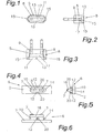
- Fig. 1 eine Draufsicht auf einen Netzstecker mit dem erfindungsgemäßen Kupplungsmittel, in vereinfachter, schematischer Darstellung;
- Fig. 2 eine Seitenansicht des Netzsteckers mit dem erfindungsgemäßen Kupplungsmittel gemäß Fig. 1;
- Fig. 3 eine Frontansicht des Netzsteckers gemäß Fig. 1 und 2;
- Fig. 4 eine Draufsicht auf das Kupplungsmittel für ein Gehäuse mit dem erfindungsgemäßen Kupplungsmittel, in vereinfachter, schematischer Darstellung;
- Fig. 5 eine Seitenansicht des Kupplungsmittels gemäß Fig. 4;
- Fig. 6 eine Frontansicht des Kupplungsmittels gemäß Fig. 4;
- Fig. 7 eine schaubildliche Darstellung der Stecker-Kupplung, insbesondere des Netzstecker-Wechselsystems, mit abgehobenem Netzstecker, in vereinfachter, schematischer Darstellung;
- Fig. 8 eine schaubildliche Darstellung der Stecker-Kupplung gemäß Fig. 7;
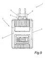
- Fig. 9 eine schaubildliche Darstellung der Stecker-Kupplung gemäß Fig. 7 mit aufgesetztem und eingerastetem Netzstecker;
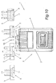
- Fig. 10 eine schaubildliche Darstellung der Stecker-Kupplung, insbesondere des Netzstecker-Wechselsystems, mit unterschiedlichen Netzsteckern, in vereinfachter, schematischer Frontansicht;
- Fig. 11 eine weitere schaubildliche Darstellung der Stecker-Kupplung, insbesondere des Netzstecker-Wechselsystems, mit unterschiedlichen Netzsteckern, in vereinfachter, schematischer Seitenansicht.
- In den Fig. 1 bis 11 ist eine Stecker-Kupplung, insbesondere ein Netzstecker-Wechselsystem 1, für elektrische Geräte 2 beschrieben, wobei dies anhand eines Ladegerätes 3 für wiederaufladbare Batterien dargestellt ist.
- Grundsätzlich ist hierzu zu erwähnen, dass ein auswechselbarer am Gehäuse 4 befestigbarer Netzstecker 5, der entsprechend eines beliebigen Länderstandards ausgebildet ist, angeordnet ist, d.h., dass ein Netzstecker 5 entsprechend den unterschiedlichsten Steckdosensystemen mit dem Gehäuse 4 des elektrischen Gerätes 2 verbunden wird, so dass für die unterschiedlichsten Länder nicht unterschiedliche Gehäuse 4 mit den unterschiedlichst angeformten bzw. ausgebildeten Netzsteckern 5 erzeugt werden müssen, sondern diese entsprechend ausgetauscht werden können. Hierzu ist am Gehäuse 4 ein Kupplungsmittel 6 mit Kontaktelementen 7 angeordnet. Der Netzstecker 5 weist ebenfalls ein entsprechendes korrespondierendes Kupplungsmittel 8 mit Kontaktelementen 9 auf. Die Kontaktelemente 7 des Gehäuses 4 sind über Leitungen, Kabeln, Kontaktstifte, Kontaktfedern, etc. mit einer in dem Gehäuse 4 angeordneten Leiterplatte, die die elektronischen Bauelemente aufweist, verbunden, wodurch eine Stromübertragung vom Netzstecker 5 zum Gerät 2 realisiert wird.
- Bei der erfindungsgemäßen Lösung wird nunmehr das Kupplungsmittel 6 am Gehäuse 4 durch einen Führungssteg 10 gebildet, wogegen das Kupplungsmittel 8 am Netzstecker 5 durch einen Hohlraum 11 ausgebildet ist, d.h. dass am Gehäuse 4 zur Aufnahme des Netzsteckers 5 zumindest ein vorspringender bzw. hervorragender Führungssteg 10 bzw. eine Führungsaufnahme angeordnet ist, wobei der Netzstecker 5 den Hohlraum 11 zur Aufnahme des Führungssteges 10 bzw. der Führungsaufnahme aufweist. Der Führungssteg 10, des Gehäuses 4 ist in den Hohlraum 11 des Netzsteckers 5 einsteckbar. Durch eine Längsverschiebung in Richtung des Führungssteges 10 und/oder eine Querbewegung und/oder Drehbewegung des Netzsteckers 5, je nach Ausbildung der Stecker-Kupplung, ist eine Fixierung des Netzsteckers 5 mit einer elektrischen Kontaktierung am Gehäuse 4 herstellbar.
- Dazu ist am Führungssteg 10 eine Vertiefung 12, Ausnehmung bzw. Einbuchtung angeordnet, in die zumindest ein korrespondierender Zapfen 13 od. dgl. des Netzsteckers 5 einrastbar bzw. einklinkbar ist, d.h., dass der Zapfen 13 aufgrund einer Bewegung bzw. Verschiebung des Netzsteckers 5 bzw. des Gehäuses 4 in die Vertiefung 12 bzw. Ausnehmung verschoben wird und somit ein sicherer Halt des Netzsteckers 5 am Gehäuse 4 erreicht wird, der nur mit erhöhtem Kraftaufwand bewusst gelöst werden kann. Selbstverständlich ist es möglich, dass die Vertiefung 12 bzw. Ausnehmung am Adapter angeordnet ist, in dem der korrespondierende Zapfen 13, der nunmehr am Führungssteg 10 angeformt ist, einrastbar bzw. einklinkbar ist. Es ist auch möglich, dass sowohl am Führungssteg 10 als auch im Hohlraum 11 eine Vertiefung 12 und ein Zapfen 13 angeordnet sind.
- Weiters weist der Führungssteg 10 einen Vorsprung 14 zur Führung des Netzsteckers 5 auf, wobei der Netzstecker 5 eine korrespondierende Nut 15 zur Aufnahme des Vorsprunges 14 aufweist, wodurch ein Abheben des Netzsteckers 5 beim Herausziehen aus der Steckdose ausgeschlossen wird. Damit die Aufsteckrichtung des Netzsteckers 5 nicht beachtet werden muss, sind im Hohlraum 11 des Netzsteckers 5 zwei derartige Nuten 15 angeordnet. Selbstverständlich ist es auch hier möglich, dass am Führungssteg 10 die Nut 15 vorgesehen ist, wobei im Netzstecker 5 der entsprechende Vorsprung 14 zur Führung bzw. Fixierung in der Nut 15 des Führungssteges 10 angeordnet ist.
- Um den Sicherheitsbestimmungen in Bezug auf eine Berührung der Kontaktelemente 9 im Netzstecker 5 zu entsprechen, ist bei dem dargestellten Ausführungsbeispiel auf den Führungssteg 10 ein abgesetzter bzw. in seiner Breite verringerter Fortsatz 16 angeordnet, in dem die Kontaktstifte bzw. Kontaktelemente 7 integriert sind. Im Hohlraum 11 des Netzsteckers 5 ist ebenfalls eine weitere in ihrer Breite verringerte Vertiefung 17 angeordnet, in die der Fortsatz 16 des Führungssteges 10 bzw. die Kontaktstifte einsetzbar ist bzw. sind, um eine Berührung der in der Vertiefung 17 angeordneten Kontaktelemente 9 zu verhindern bzw. die Berührung der Kontaktelemente 9 mit den Fingern auszuschließen. Dies bedeutet, dass der Fortsatz 16 und die zusätzliche Vertiefung 17 in ihrer Breite und Höhe derart dimensioniert bzw. ausgebildet sind, dass beispielsweise Kinder beim Einstecken des Netzsteckers 5 in die Steckdose ohne angeschlossenes Gerät 2, nicht durch Eindringung mit den Fingern in den Hohlraum 11 die darin angeordneten Kontaktelemente 9 berühren können.
- Ein derartiger Sicherheitsschutz kann auch anderwärtig erreicht werden, indem die Kontaktstifte bzw. Kontaktfedern 7 über den Führungssteg 10 hinausragen, wobei im Hohlraum 11 eine oder mehrere Vertiefungen 17 angeordnet sind, in welchen die Kontaktelemente 9, insbesondere Kontaktflächen, angeordnet sind. Hierbei ist es wiederum erforderlich, dass die Vertiefung 17 im Hohlraum 11 derartig dimensioniert ist, dass ein Berühren der darin angeordneten Kontaktelemente 9 nicht möglich ist. Bei dieser Ausführungsform ist es nicht erforderlich, dass am Führungssteg 10 ein zusätzlicher abgesetzter Fortsatz 16 vorhanden ist. Der Fortsatz 16 hat lediglich den Vorteil, dass die darin integrierten Kontaktstifte bzw. Kontaktelemente 7 gegen Verbiegung geschützt werden und somit nur geringfügig über den Fortsatz 16 hinausragen müssen, um ein Kontaktierung mit dem Kontaktelement 9 im Netzstecker 5 herstellen zu können.
- Grundsätzlich ist es auch möglich, dass beidseitig des Führungssteges 10 die Kontaktelemente 7 angeordnet sind oder dass die Kontaktelemente 7 direkt, wie dargestellt, im Führungssteg 10 integriert sind. Bevorzugt werden die Kontaktelemente 7 in den Führungssteg 10 integriert, wobei der Führungssteg 10 bevorzugt aus Kunststoff, insbesondere einem Kunststoffspritzteil gebildet ist und somit keine elektrische Isolierung der Kontaktelemente 7 notwendig ist. Bei dem Aufbau bzw. der Anordnung der Kontaktelemente 7 muss lediglich gewährleistet sein, dass die Kontaktelemente 7 mit den Kontaktelementen 9, insbesondere den Kontaktflächen, im Netzstecker 5 eine elektrische Verbindung herstellen können.
- Bei der erfindungsgemäßen Lösung ist es möglich, dass das Kupplungsmittel 8 am Gehäuse 4 derart dimensioniert wird, dass die äußere Form eines Netzsteckers 5, insbesondere eines Euro- bzw. Schukosteckers, nicht verändert wird, d.h., dass der Führungssteg 10 derart in seiner Länge, Breite und Höhe ausgebildet wird, dass dieser innerhalb der vorgegebenen äußeren Form eines Euro- bzw. Schukosteckers in den darin anzuordnenden Hohlraum 11 einsteckbar ist. Bevorzugt wird dabei der Führungssteg 10, wie dargestellt, durch eine elliptische bzw. längliche Form gebildet. Dies hat den Vorteil, dass ein Verdrehen des Netzsteckers 5 unterbunden werden kann, wobei durch die Breite des Führungssteges 10 eine hohe Festigkeit des Führungssteges 10 erreicht wird. Auch die Anordnung der Kontaktelemente 7 sowie der einzelnen Teile für die Fixierung des Netzsteckers 5 können sehr einfach ausgebildet werden.
- In den Fig. 7 bis 9 ist ein Ablauf für das Verbinden des Netzsteckers 5 am Gehäuse 4 eines Gerätes 2, insbesondere des dargestellten Ladegerätes 3, dargestellt, wobei der Bewegungsablauf durch die Pfeile 18 und 19 dargestellt ist. Dabei wird zuerst der Netzstecker 5 auf das Gehäuse 4, insbesondere auf den Führungssteg 10, außermittig in einen Führungskanal aufgesteckt, gemäß Pfeil 18. Anschließend wird aufgrund einer Bewegung des Netzsteckers 5 bzw. des Gehäuses 4, insbesondere einer Längsbewegung entlang des Führungssteges 10, gemäß Pfeil 19, der Netzstecker 5 durch Einrasten des Zapfens 13 und des Vorsprunges 14 in die Vertiefung 12 und die Nut 15 fixiert und positioniert. Das Lösen des Netzsteckers 5 vom Gehäuse 4 erfolgt in umgekehrter Reihenfolge.
- Aufgrund der Ausbildung des Netzstecker-Wechselsystems 1 ist es möglich, dass der Führungssteg 10 auf jeder Seitenfläche des Gehäuses 4 angeordnet werden kann, da am Gehäuse nur ein sehr schmaler Führungssteg 10 angeformt werden muss. Es ist auch möglich, das Netzstecker-Wechselsystem 1 schwenkbar auszubilden, d.h., dass der Führungssteg 10 auf einer beweglichen bzw. schwenkbaren Grundplatte, nicht dargestellt, am Gehäuse 4 angeordnet wird, so dass durch Schwenken dieser Grundplatte beispielsweise eine Drehung des Netzsteckers 5 um 90° möglich ist. Eine derartige Darstellung ist in den Fig. 10 und 11 ersichtlich.
- Weiters sind in den Fig. 10 und 11 unterschiedliche Netzstecker 5 gezeigt. Dabei sind jedoch nur die wesentlichsten Netzstecker 5 dargestellt. Wie nun aus diesen Darstellungen ersichtlich ist, wird durch die spezielle Ausbildung erreicht, dass die äußere Form der Netzstecker 5 nicht verändert wird, d.h., dass keine zusätzlichen Anformteile entsprechend dem Stand der Technik, wie beispielsweise eine Befestigungsplatte für ein derartiges Netzstecker-Wechselsystem 1, benötigt werden, da das Kupplungsmittel 8, insbesondere der Hohlraum 11, einfach in die Netzsteckerform des Netzsteckers 5 integriert werden kann.
- Die Ausgestaltung des Führungssteges 10 ist nicht auf das dargestellte Ausführungsbeispiel beschränkt, wobei anschließend einige Lösungsvorschläge für die Ausführung des Führungssteges 10, zu dem das Kupplungsmittel 8 am Netzstecker 5 korrespondierend ausgeführt wird, erwähnt werden, jedoch nicht dargestellt werden.
- Dabei ist es möglich, dass beispielsweise am Gehäuse 4 zwei spiegelbildlich ausgebildete Führungsstege 10 angeordnet sind, die parallel zueinander positioniert sind, d.h., dass der Führungssteg 10 nicht mehr durch einen einzigen Baukörper, wie dargestellt, gebildet wird, sondern dass nur einzelne schmale Führungsstege 10 angeordnet sind. Der Netzstecker 5 kann hierzu das gezeigte Kupplungsmittel 8, insbesondere den Hohlraum 11, aufweisen oder es ist auch möglich, dass im Netzstecker 5 zwei Hohlräume 11, insbesondere Schlitze, angeordnet werden. Um beispielsweise für die Fixierung des Netzsteckers 5 eine Drehbewegung durchführen zu können, ist es möglich, dass der Führungssteg 10 kreisförmig bzw. rund ausgebildet wird, so dass nach dem Aufstecken des Netzsteckers 5 über eine Drehbewegung der Zapfen 13 in die Vertiefung 12 eingedreht wird bzw. einrastet.
- Dabei ist es auch möglich, dass am Führungssteg 10 Führungskanäle 20 für den Zapfen 13, wie in den Fig. 4 bis 6 eingezeichnet, angeordnet sind. Im Führungskanal 20 kann die Vertiefung 12 zum Einrasten des Zapfens 13 angeordnet sein bzw. neben diesem angeordnet sein. Durch den Führungskanal 20 wird lediglich erreicht, dass der Zapfen 13 bereits vor dem Einrasten in die Vertiefung 12 entlang des Führungskanals 20 geführt wird. Diese Anwendung empfiehlt sich besonders dann, wenn nur eine Vertikalbewegung, also ein einfaches Aufstecken des Netzsteckers 5 auf das Gehäuse 4 realisiert werden soll, da somit über den Führungskanal 20 eine Positionierung zu der Vertiefung 12 vorhanden ist.
- Wesentlich ist bei der erfindungsgemäßen Stecker-Kupplung, dass immer ein Kupplungsmittel 6 oder 8 durch einen entsprechenden Führungssteg 10 gebildet wird und das weitere Kupplungsmittel 8 oder 6 einen korrespondierenden Hohlraum 11, in dem der Führungssteg 10 aufgesteckt wird, aufweist. Es ist auch möglich, dass am Führungssteg 10 bzw. im Hohlraum 11 bewegliche, insbesondere federnde Elemente zum Fixieren, Einrasten bzw. Positionieren angeordnet werden können. Selbstverständlich ist es möglich, dass der Netzstecker 5 bzw. Adapter als zwei oder dreipoliger Netzstecker 5 ausgebildet ist und dass entsprechend viele Kontaktelemente 7, 9 am Netzstecker 5 und am Führungssteg 10 angeordnet sind.
- Es ist auch möglich, dass der Adapter als elektrisches Zusatzgerät, wie beispielsweise als Hochsetzsteller, ausgebildet ist, d.h., dass über eine derartige Stecker-Kupplung ein weiteres elektronisches Gerät mit dem Gerät 2, insbesondere dem Ladegerät 3, gekoppelt werden kann. Hierzu ist es möglich, dass nicht nur Kontaktelemente 7, 9 für die Stromübertragung angeordnet werden, sondern weitere derartige Kontaktelemente 7 oder 9 für eine Datenübertragung eingesetzt werden.
- Eine spezielle Anwendung einer derartigen Stecker-Kupplung ist auch in der Kabeltechnik möglich, wobei hierbei am Führungssteg 10, insbesondere mit den Kontaktelementen 7, ein Kabel, insbesondere ein Verlängerungskabel, angeschlossen ist. Dabei ist am Ende eines Kabels das Kupplungsmittel 6, insbesondere der Führungssteg 10, angeordnet, wobei beispielsweise im Inneren des Gehäuses des Führungssteges 10 Klemmelemente angeordnet sind, mit denen das Kabel, insbesondere die Litzen, kontaktiert werden.
- Aufgrund der einfachen baulichen Ausführung der Stecker-Kupplung ist es auch möglich, dass der Hohlraum 11 im Gehäuse 4 und der Führungssteg 10 am Netzstecker 5 angeordnet ist, d.h., dass am Netzstecker 5 lediglich der Führungssteg 10 angeformt werden muss, wogegen am Gehäuse 4 der Hohlraum 11 angeordnet wird.
- Abschließend sei darauf hingewiesen, dass in den zuvor beschriebenen Ausführungsbeispielen einzelne Zustände bzw. Darstellungen unproportional dargestellt wurden, um das Verständnis der erfindungsgemäßen Lösung zu verbessern. Des Weiteren können auch einzelne Zustände bzw. Darstellungen der zuvor beschriebenen Merkmalskombinationen der einzelnen Ausführungsbeispiele in Verbindung mit anderen Einzelmerkmalen aus anderen Ausführungsbeispielen eigenständige, erfindungsgemäße Lösungen bilden.
Claims (11)
- Stecker-Kupplung, insbesondere Netzstecker-Wechselsystem (1), für elektrische Geräte, insbesondere für ein Ladegerät (3), bei der ein auswechselbarer, am Gehäuse (4) befestigbarer Netzstecker (5), angeordnet ist, wobei am Gehäuse (4) zumindest ein vorspringender Führungssteg (10) mit Kontaktelementen (7) angeordnet ist und der Netzstecker (5) mit Kontaktelementen (9) zumindest einen entsprechend korrespondierenden Hohlraum (11) zur Aufnahme des Führungssteges (10) aufweist, dadurch gekennzeichnet, dass am Führungssteg (10) eine Vertiefung (12) und am Netzstecker (5) ein korrespondierender, in die Vertiefung (12) einrastender Zapfen (13) und/oder am Netzstecker (5) eine Vertiefung (12) und am Führungssteg (10) ein korrespondierender, in die Vertiefung (12) einrastender Zapfen (13) angeordnet ist, so dass durch eine entsprechende Bewegung des Netzsteckers (5) gegenüber dem Gehäuse (4) eine Fixierung des Netzsteckers (5) am Gehäuse (4) mit einer Verbindung der Kontaktelemente (9) des Netzsteckers (5) mit den Kontaktelementen (7) des Führungssteges (10) herstellbar ist.
- Stecker-Kupplung nach Anspruch 1, dadurch gekennzeichnet, dass der Führungssteg (10) einen Vorsprung (14) und der Netzstecker (5) eine korrespondierende Nut (15) zur Aufnahme des Vorsprungs (14) aufweist.
- Stecker-Kupplung nach Anspruch 1 oder 2, dadurch gekennzeichnet, dass der Netzstecker (5) einen Vorsprung (14) und der Führungssteg (10) eine korrespondierende Nut (15) zur Aufnahme des Vorsprungs (14) aufweist.
- Stecker-Kupplung nach einem der Ansprüche 1 bis 3, dadurch gekennzeichnet, dass die Kontaktelemente (7) beidseitig des Führungssteges (10) angeordnet sind oder dass die Kontaktelemente (7) direkt im Führungssteg (10) integriert sind.
- Stecker-Kupplung nach einem der Ansprüche 1 bis 4, dadurch gekennzeichnet, dass am Gehäuse (4) zwei spiegelbildlich ausgebildete Führungsstege (10) angeordnet sind, die parallel zueinander positioniert sind.
- Stecker-Kupplung nach einem der Ansprüche 1 bis 5, dadurch gekennzeichnet, dass auf dem Führungssteg (10) ein abgesetzter bzw. in seiner Breite verringerter Fortsatz (16) angeordnet ist, in dem die Kontaktelemente (7) integriert sind.
- Stecker-Kupplung nach Anspruch 6, dadurch gekennzeichnet, dass im Hohlraum (11) des Netzsteckers (5) eine weitere in ihrer Breite verringerte Vertiefung (17) angeordnet ist, in die der Fortsatz (16) des Führungssteges (10) bzw. die Kontaktelemente (7) einsetzbar sind, um eine Berührung der in der Vertiefung (17) angeordneten Kontaktelemente (9) zu verhindern.
- Stecker-Kupplung nach einem der Ansprüche 1 bis 7, dadurch gekennzeichnet, dass die Kontaktelemente (7) über den Führungssteg (10) hinausragen, und dass im Hohlraum (11) eine oder mehrere Vertiefungen (17) mit darin angeordneten Kontaktelementen (9) vorgesehen sind. -
- Stecker-Kupplung nach einem der Ansprüche 1 bis 8, dadurch gekennzeichnet, dass der Netzstecker (5) als zwei- oder dreipoliger Netzstecker (5) ausgebildet ist, und dass entsprechend viele Kontaktelemente (7, 9) am Netzstecker (5) und am Führungssteg (10) angeordnet sind.
- Stecker-Kupplung nach einem der Ansprüche 1 bis 9, dadurch gekennzeichnet, dass am Führungssteg (10) ein Kabel, insbesondere ein Verlängerungskabel, angeschlossen ist.
- Ladegerät (3) für elektrische Geräte, insbesondere für wiederaufladbare Batterien, bei dem ein auswechselbarer, am Gehäuse (4) befestigbarer Netzstecker (5) angeordnet ist, wobei am Gehäuse (4) zumindest ein Führungssteg (10) mit Kontaktelementen (7) angeordnet ist und der Netzstecker (5) zumindest einen entsprechenden korrespondierenden Hohlraum (11) zur Aufnahme des Führungssteges (10) aufweist, dadurch gekennzeichnet, dass eine Stecker-Kupplung zur Verbindung des Netzsteckers (5) nach einem der Ansprüche 1 bis 10 vorgesehen ist.
Applications Claiming Priority (3)
| Application Number | Priority Date | Filing Date | Title |
|---|---|---|---|
| AT0118802A AT412246B (de) | 2002-08-05 | 2002-08-05 | Stecker-kupplung für elektrische geräte und ladegerät mit einer derartigen stecker-kupplung |
| AT11882002 | 2002-08-05 | ||
| PCT/AT2003/000225 WO2004013937A1 (de) | 2002-08-05 | 2003-08-05 | Stecker-kupplung für elektrische geräte und ladegerät mit einer derartigen stecker-kupplung |
Publications (2)
| Publication Number | Publication Date |
|---|---|
| EP1527501A1 EP1527501A1 (de) | 2005-05-04 |
| EP1527501B1 true EP1527501B1 (de) | 2007-03-07 |
Family
ID=31192776
Family Applications (1)
| Application Number | Title | Priority Date | Filing Date |
|---|---|---|---|
| EP03766063A Expired - Lifetime EP1527501B1 (de) | 2002-08-05 | 2003-08-05 | Steckerkupplung für elektrische Geräte und Ladegerät mit einer derartigen Steckerkupplung |
Country Status (6)
| Country | Link |
|---|---|
| EP (1) | EP1527501B1 (de) |
| AT (2) | AT412246B (de) |
| AU (1) | AU2003249747A1 (de) |
| DE (1) | DE50306762D1 (de) |
| ES (1) | ES2283828T3 (de) |
| WO (1) | WO2004013937A1 (de) |
Cited By (1)
| Publication number | Priority date | Publication date | Assignee | Title |
|---|---|---|---|---|
| DE102012020641A1 (de) | 2012-10-20 | 2014-04-24 | Volkswagen Aktiengesellschaft | Adapter und Stecker zur Verbindung mit dem Adapter |
Families Citing this family (1)
| Publication number | Priority date | Publication date | Assignee | Title |
|---|---|---|---|---|
| DE102005041116B4 (de) * | 2005-08-30 | 2009-12-10 | Friwo Gerätebau Gmbh | Steckernetzgerät mit auswechselbarer Netzsteckereinheit |
Family Cites Families (4)
| Publication number | Priority date | Publication date | Assignee | Title |
|---|---|---|---|---|
| US5684689A (en) * | 1996-06-19 | 1997-11-04 | Advanced Mobile Solutions, Inc. | Interchangeable plug power supply with automatically adjusting input voltage receiving mechanism |
| TW328403U (en) * | 1997-05-09 | 1998-03-11 | Formosa Electronicindustries Inc | Ac/dc power supplier having a replaceable plug |
| US5998964A (en) * | 1998-03-17 | 1999-12-07 | Ipr Industries, Ltd. | Portable appliance charging system |
| US5934921A (en) * | 1998-06-24 | 1999-08-10 | Rotrans Electrical Corp., Ltd. | Power supply and the joint structure of adaptor plug thereof |
-
2002
- 2002-08-05 AT AT0118802A patent/AT412246B/de not_active IP Right Cessation
-
2003
- 2003-08-05 ES ES03766063T patent/ES2283828T3/es not_active Expired - Lifetime
- 2003-08-05 AU AU2003249747A patent/AU2003249747A1/en not_active Abandoned
- 2003-08-05 AT AT03766063T patent/ATE356450T1/de not_active IP Right Cessation
- 2003-08-05 EP EP03766063A patent/EP1527501B1/de not_active Expired - Lifetime
- 2003-08-05 WO PCT/AT2003/000225 patent/WO2004013937A1/de not_active Ceased
- 2003-08-05 DE DE50306762T patent/DE50306762D1/de not_active Expired - Lifetime
Cited By (1)
| Publication number | Priority date | Publication date | Assignee | Title |
|---|---|---|---|---|
| DE102012020641A1 (de) | 2012-10-20 | 2014-04-24 | Volkswagen Aktiengesellschaft | Adapter und Stecker zur Verbindung mit dem Adapter |
Also Published As
| Publication number | Publication date |
|---|---|
| WO2004013937A1 (de) | 2004-02-12 |
| DE50306762D1 (de) | 2007-04-19 |
| ES2283828T3 (es) | 2007-11-01 |
| AU2003249747A1 (en) | 2004-02-23 |
| ATA11882002A (de) | 2004-04-15 |
| AT412246B (de) | 2004-11-25 |
| EP1527501A1 (de) | 2005-05-04 |
| ATE356450T1 (de) | 2007-03-15 |
Similar Documents
| Publication | Publication Date | Title |
|---|---|---|
| EP2510590B1 (de) | Systemsteckverbinder mit adaptermodul | |
| EP2182592B1 (de) | Steckverbinder | |
| DE102020110979A1 (de) | Steckverbinder einer elektrischen Steckverbindung sowie damit gebildete elektrische Steckverbindung | |
| EP2810342B1 (de) | Elektrisches kupplungselement | |
| DE102005041116B4 (de) | Steckernetzgerät mit auswechselbarer Netzsteckereinheit | |
| DE102012017429A1 (de) | Prüfklemmenblock | |
| DE202013005015U1 (de) | Solarmodul mit kombinierter mechanischer und elektrischer Steckverbindung zur Erzeugung von elektrischem Strom | |
| DE2807017A1 (de) | Mehrpolige kodierbare steckverbindung | |
| WO2021043525A1 (de) | Verbindungsvorrichtung für leuchtmitteltreiber | |
| EP2347477A1 (de) | Elektrische steckvorrichtung | |
| WO2021004893A1 (de) | Direktsteckverbinder | |
| DE10045714A1 (de) | Steckverbinder für zumindest einen Flachfolienleiter | |
| DE112009001573B4 (de) | Hochvolt-Steckverbindung sowie Verwendung einer solchen | |
| EP1595311B1 (de) | Steckverbindung | |
| AT412246B (de) | Stecker-kupplung für elektrische geräte und ladegerät mit einer derartigen stecker-kupplung | |
| DE202019103837U1 (de) | Werkzeugfreier Lichtkasten | |
| DE102004030440B4 (de) | Elektrischer Anschlussverbinder mit Sperrplatte | |
| EP1523790A1 (de) | Steckverbindung mit zus tzlicher kontakteinrichtung, i nsbesondere zur daten bertragung | |
| DE2723725C3 (de) | Elektrische Mehrfachkupplung | |
| DE202008014441U1 (de) | Steckverbinder | |
| EP3806249A1 (de) | Steckdosenadapter mit ladeanschluss | |
| DE4437791C1 (de) | Kabelsteckverbinder | |
| EP1094561B1 (de) | Mehrpoliges elektrisches Steckverbindungssystem | |
| WO2009013080A2 (de) | Elektrische steckverbindung | |
| DE102019126950A1 (de) | Stromschiene für Leuchten oder elektrische Einheiten |
Legal Events
| Date | Code | Title | Description |
|---|---|---|---|
| PUAI | Public reference made under article 153(3) epc to a published international application that has entered the european phase |
Free format text: ORIGINAL CODE: 0009012 |
|
| 17P | Request for examination filed |
Effective date: 20040802 |
|
| AK | Designated contracting states |
Kind code of ref document: A1 Designated state(s): AT BE BG CH CY CZ DE DK EE ES FI FR GB GR HU IE IT LI LU MC NL PT RO SE SI SK TR |
|
| AX | Request for extension of the european patent |
Extension state: AL LT LV MK |
|
| DAX | Request for extension of the european patent (deleted) | ||
| GRAP | Despatch of communication of intention to grant a patent |
Free format text: ORIGINAL CODE: EPIDOSNIGR1 |
|
| RTI1 | Title (correction) |
Free format text: PLUG COUPLING FOR ELECTRICAL DEVICES AND CHARGER COMPRISING SAID PLUG COUPLING |
|
| GRAS | Grant fee paid |
Free format text: ORIGINAL CODE: EPIDOSNIGR3 |
|
| GRAA | (expected) grant |
Free format text: ORIGINAL CODE: 0009210 |
|
| AK | Designated contracting states |
Kind code of ref document: B1 Designated state(s): AT BE BG CH CY CZ DE DK EE ES FI FR GB GR HU IE IT LI LU MC NL PT RO SE SI SK TR |
|
| PG25 | Lapsed in a contracting state [announced via postgrant information from national office to epo] |
Ref country code: NL Free format text: LAPSE BECAUSE OF FAILURE TO SUBMIT A TRANSLATION OF THE DESCRIPTION OR TO PAY THE FEE WITHIN THE PRESCRIBED TIME-LIMIT Effective date: 20070307 Ref country code: FI Free format text: LAPSE BECAUSE OF FAILURE TO SUBMIT A TRANSLATION OF THE DESCRIPTION OR TO PAY THE FEE WITHIN THE PRESCRIBED TIME-LIMIT Effective date: 20070307 Ref country code: SI Free format text: LAPSE BECAUSE OF FAILURE TO SUBMIT A TRANSLATION OF THE DESCRIPTION OR TO PAY THE FEE WITHIN THE PRESCRIBED TIME-LIMIT Effective date: 20070307 Ref country code: IE Free format text: LAPSE BECAUSE OF FAILURE TO SUBMIT A TRANSLATION OF THE DESCRIPTION OR TO PAY THE FEE WITHIN THE PRESCRIBED TIME-LIMIT Effective date: 20070307 |
|
| REG | Reference to a national code |
Ref country code: GB Ref legal event code: FG4D Free format text: NOT ENGLISH |
|
| REG | Reference to a national code |
Ref country code: CH Ref legal event code: EP |
|
| REG | Reference to a national code |
Ref country code: CH Ref legal event code: NV Representative=s name: A. BRAUN, BRAUN, HERITIER, ESCHMANN AG PATENTANWAE |
|
| REF | Corresponds to: |
Ref document number: 50306762 Country of ref document: DE Date of ref document: 20070419 Kind code of ref document: P |
|
| REG | Reference to a national code |
Ref country code: IE Ref legal event code: FG4D Free format text: LANGUAGE OF EP DOCUMENT: GERMAN |
|
| PG25 | Lapsed in a contracting state [announced via postgrant information from national office to epo] |
Ref country code: SE Free format text: LAPSE BECAUSE OF FAILURE TO SUBMIT A TRANSLATION OF THE DESCRIPTION OR TO PAY THE FEE WITHIN THE PRESCRIBED TIME-LIMIT Effective date: 20070607 |
|
| RAP2 | Party data changed (patent owner data changed or rights of a patent transferred) |
Owner name: FRONIUS INTERNATIONAL GMBH |
|
| GBT | Gb: translation of ep patent filed (gb section 77(6)(a)/1977) |
Effective date: 20070531 |
|
| NLT2 | Nl: modifications (of names), taken from the european patent patent bulletin |
Owner name: FRONIUS INTERNATIONAL GMBH Effective date: 20070620 |
|
| PG25 | Lapsed in a contracting state [announced via postgrant information from national office to epo] |
Ref country code: PT Free format text: LAPSE BECAUSE OF FAILURE TO SUBMIT A TRANSLATION OF THE DESCRIPTION OR TO PAY THE FEE WITHIN THE PRESCRIBED TIME-LIMIT Effective date: 20070807 |
|
| ET | Fr: translation filed | ||
| REG | Reference to a national code |
Ref country code: FR Ref legal event code: CA |
|
| NLV1 | Nl: lapsed or annulled due to failure to fulfill the requirements of art. 29p and 29m of the patents act | ||
| REG | Reference to a national code |
Ref country code: IE Ref legal event code: FD4D |
|
| REG | Reference to a national code |
Ref country code: ES Ref legal event code: FG2A Ref document number: 2283828 Country of ref document: ES Kind code of ref document: T3 |
|
| PG25 | Lapsed in a contracting state [announced via postgrant information from national office to epo] |
Ref country code: SK Free format text: LAPSE BECAUSE OF FAILURE TO SUBMIT A TRANSLATION OF THE DESCRIPTION OR TO PAY THE FEE WITHIN THE PRESCRIBED TIME-LIMIT Effective date: 20070307 |
|
| PG25 | Lapsed in a contracting state [announced via postgrant information from national office to epo] |
Ref country code: RO Free format text: LAPSE BECAUSE OF FAILURE TO SUBMIT A TRANSLATION OF THE DESCRIPTION OR TO PAY THE FEE WITHIN THE PRESCRIBED TIME-LIMIT Effective date: 20070307 Ref country code: CZ Free format text: LAPSE BECAUSE OF FAILURE TO SUBMIT A TRANSLATION OF THE DESCRIPTION OR TO PAY THE FEE WITHIN THE PRESCRIBED TIME-LIMIT Effective date: 20070307 |
|
| PLBE | No opposition filed within time limit |
Free format text: ORIGINAL CODE: 0009261 |
|
| STAA | Information on the status of an ep patent application or granted ep patent |
Free format text: STATUS: NO OPPOSITION FILED WITHIN TIME LIMIT |
|
| PG25 | Lapsed in a contracting state [announced via postgrant information from national office to epo] |
Ref country code: DK Free format text: LAPSE BECAUSE OF FAILURE TO SUBMIT A TRANSLATION OF THE DESCRIPTION OR TO PAY THE FEE WITHIN THE PRESCRIBED TIME-LIMIT Effective date: 20070307 |
|
| 26N | No opposition filed |
Effective date: 20071210 |
|
| BERE | Be: lapsed |
Owner name: FRONIUS INTERNATIONAL GMBH Effective date: 20070831 |
|
| PG25 | Lapsed in a contracting state [announced via postgrant information from national office to epo] |
Ref country code: MC Free format text: LAPSE BECAUSE OF NON-PAYMENT OF DUE FEES Effective date: 20070831 Ref country code: GR Free format text: LAPSE BECAUSE OF FAILURE TO SUBMIT A TRANSLATION OF THE DESCRIPTION OR TO PAY THE FEE WITHIN THE PRESCRIBED TIME-LIMIT Effective date: 20070608 |
|
| REG | Reference to a national code |
Ref country code: CH Ref legal event code: PFA Owner name: FRONIUS INTERNATIONAL GMBH Free format text: FRONIUS INTERNATIONAL GMBH#VORCHDORFER STRASSE 40#4643 PETTENBACH (AT) -TRANSFER TO- FRONIUS INTERNATIONAL GMBH#VORCHDORFER STRASSE 40#4643 PETTENBACH (AT) |
|
| PG25 | Lapsed in a contracting state [announced via postgrant information from national office to epo] |
Ref country code: BE Free format text: LAPSE BECAUSE OF NON-PAYMENT OF DUE FEES Effective date: 20070831 |
|
| PG25 | Lapsed in a contracting state [announced via postgrant information from national office to epo] |
Ref country code: AT Free format text: LAPSE BECAUSE OF NON-PAYMENT OF DUE FEES Effective date: 20070805 |
|
| PG25 | Lapsed in a contracting state [announced via postgrant information from national office to epo] |
Ref country code: EE Free format text: LAPSE BECAUSE OF FAILURE TO SUBMIT A TRANSLATION OF THE DESCRIPTION OR TO PAY THE FEE WITHIN THE PRESCRIBED TIME-LIMIT Effective date: 20070307 |
|
| PG25 | Lapsed in a contracting state [announced via postgrant information from national office to epo] |
Ref country code: CY Free format text: LAPSE BECAUSE OF FAILURE TO SUBMIT A TRANSLATION OF THE DESCRIPTION OR TO PAY THE FEE WITHIN THE PRESCRIBED TIME-LIMIT Effective date: 20070307 |
|
| PG25 | Lapsed in a contracting state [announced via postgrant information from national office to epo] |
Ref country code: LU Free format text: LAPSE BECAUSE OF NON-PAYMENT OF DUE FEES Effective date: 20070805 Ref country code: BG Free format text: LAPSE BECAUSE OF FAILURE TO SUBMIT A TRANSLATION OF THE DESCRIPTION OR TO PAY THE FEE WITHIN THE PRESCRIBED TIME-LIMIT Effective date: 20070607 |
|
| PG25 | Lapsed in a contracting state [announced via postgrant information from national office to epo] |
Ref country code: HU Free format text: LAPSE BECAUSE OF FAILURE TO SUBMIT A TRANSLATION OF THE DESCRIPTION OR TO PAY THE FEE WITHIN THE PRESCRIBED TIME-LIMIT Effective date: 20070908 Ref country code: TR Free format text: LAPSE BECAUSE OF FAILURE TO SUBMIT A TRANSLATION OF THE DESCRIPTION OR TO PAY THE FEE WITHIN THE PRESCRIBED TIME-LIMIT Effective date: 20070307 |
|
| PGFP | Annual fee paid to national office [announced via postgrant information from national office to epo] |
Ref country code: CH Payment date: 20110823 Year of fee payment: 9 |
|
| PGFP | Annual fee paid to national office [announced via postgrant information from national office to epo] |
Ref country code: ES Payment date: 20130807 Year of fee payment: 11 |
|
| PGFP | Annual fee paid to national office [announced via postgrant information from national office to epo] |
Ref country code: GB Payment date: 20130902 Year of fee payment: 11 Ref country code: FR Payment date: 20130730 Year of fee payment: 11 |
|
| PGFP | Annual fee paid to national office [announced via postgrant information from national office to epo] |
Ref country code: IT Payment date: 20130723 Year of fee payment: 11 |
|
| REG | Reference to a national code |
Ref country code: CH Ref legal event code: PL |
|
| PG25 | Lapsed in a contracting state [announced via postgrant information from national office to epo] |
Ref country code: CH Free format text: LAPSE BECAUSE OF NON-PAYMENT OF DUE FEES Effective date: 20130831 Ref country code: LI Free format text: LAPSE BECAUSE OF NON-PAYMENT OF DUE FEES Effective date: 20130831 |
|
| PGFP | Annual fee paid to national office [announced via postgrant information from national office to epo] |
Ref country code: DE Payment date: 20141020 Year of fee payment: 12 |
|
| GBPC | Gb: european patent ceased through non-payment of renewal fee |
Effective date: 20140805 |
|
| PG25 | Lapsed in a contracting state [announced via postgrant information from national office to epo] |
Ref country code: IT Free format text: LAPSE BECAUSE OF NON-PAYMENT OF DUE FEES Effective date: 20140805 |
|
| REG | Reference to a national code |
Ref country code: FR Ref legal event code: ST Effective date: 20150430 |
|
| PG25 | Lapsed in a contracting state [announced via postgrant information from national office to epo] |
Ref country code: GB Free format text: LAPSE BECAUSE OF NON-PAYMENT OF DUE FEES Effective date: 20140805 |
|
| PG25 | Lapsed in a contracting state [announced via postgrant information from national office to epo] |
Ref country code: FR Free format text: LAPSE BECAUSE OF NON-PAYMENT OF DUE FEES Effective date: 20140901 |
|
| REG | Reference to a national code |
Ref country code: DE Ref legal event code: R119 Ref document number: 50306762 Country of ref document: DE |
|
| PG25 | Lapsed in a contracting state [announced via postgrant information from national office to epo] |
Ref country code: ES Free format text: LAPSE BECAUSE OF NON-PAYMENT OF DUE FEES Effective date: 20140806 Ref country code: DE Free format text: LAPSE BECAUSE OF NON-PAYMENT OF DUE FEES Effective date: 20160301 |