EP1527263B1 - Procede d'adaptation applicative d'une commande de moteur et commande de moteur obtenue selon ledit procede - Google Patents
Procede d'adaptation applicative d'une commande de moteur et commande de moteur obtenue selon ledit procede Download PDFInfo
- Publication number
- EP1527263B1 EP1527263B1 EP03766367A EP03766367A EP1527263B1 EP 1527263 B1 EP1527263 B1 EP 1527263B1 EP 03766367 A EP03766367 A EP 03766367A EP 03766367 A EP03766367 A EP 03766367A EP 1527263 B1 EP1527263 B1 EP 1527263B1
- Authority
- EP
- European Patent Office
- Prior art keywords
- temperature
- catalytic converter
- catalyst
- detected
- determined
- Prior art date
- Legal status (The legal status is an assumption and is not a legal conclusion. Google has not performed a legal analysis and makes no representation as to the accuracy of the status listed.)
- Expired - Lifetime
Links
Images


Classifications
-
- F—MECHANICAL ENGINEERING; LIGHTING; HEATING; WEAPONS; BLASTING
- F01—MACHINES OR ENGINES IN GENERAL; ENGINE PLANTS IN GENERAL; STEAM ENGINES
- F01N—GAS-FLOW SILENCERS OR EXHAUST APPARATUS FOR MACHINES OR ENGINES IN GENERAL; GAS-FLOW SILENCERS OR EXHAUST APPARATUS FOR INTERNAL-COMBUSTION ENGINES
- F01N3/00—Exhaust or silencing apparatus having means for purifying, rendering innocuous, or otherwise treating exhaust
- F01N3/08—Exhaust or silencing apparatus having means for purifying, rendering innocuous, or otherwise treating exhaust for rendering innocuous
- F01N3/0807—Exhaust or silencing apparatus having means for purifying, rendering innocuous, or otherwise treating exhaust for rendering innocuous by using absorbents or adsorbents
- F01N3/0828—Exhaust or silencing apparatus having means for purifying, rendering innocuous, or otherwise treating exhaust for rendering innocuous by using absorbents or adsorbents characterised by the absorbed or adsorbed substances
- F01N3/0842—Nitrogen oxides
-
- F—MECHANICAL ENGINEERING; LIGHTING; HEATING; WEAPONS; BLASTING
- F01—MACHINES OR ENGINES IN GENERAL; ENGINE PLANTS IN GENERAL; STEAM ENGINES
- F01N—GAS-FLOW SILENCERS OR EXHAUST APPARATUS FOR MACHINES OR ENGINES IN GENERAL; GAS-FLOW SILENCERS OR EXHAUST APPARATUS FOR INTERNAL-COMBUSTION ENGINES
- F01N11/00—Monitoring or diagnostic devices for exhaust-gas treatment apparatus
- F01N11/002—Monitoring or diagnostic devices for exhaust-gas treatment apparatus the diagnostic devices measuring or estimating temperature or pressure in, or downstream of the exhaust apparatus
-
- F—MECHANICAL ENGINEERING; LIGHTING; HEATING; WEAPONS; BLASTING
- F02—COMBUSTION ENGINES; HOT-GAS OR COMBUSTION-PRODUCT ENGINE PLANTS
- F02D—CONTROLLING COMBUSTION ENGINES
- F02D41/00—Electrical control of supply of combustible mixture or its constituents
- F02D41/02—Circuit arrangements for generating control signals
- F02D41/021—Introducing corrections for particular conditions exterior to the engine
- F02D41/0235—Introducing corrections for particular conditions exterior to the engine in relation with the state of the exhaust gas treating apparatus
-
- G—PHYSICS
- G01—MEASURING; TESTING
- G01K—MEASURING TEMPERATURE; MEASURING QUANTITY OF HEAT; THERMALLY-SENSITIVE ELEMENTS NOT OTHERWISE PROVIDED FOR
- G01K7/00—Measuring temperature based on the use of electric or magnetic elements directly sensitive to heat ; Power supply therefor, e.g. using thermoelectric elements
- G01K7/42—Circuits effecting compensation of thermal inertia; Circuits for predicting the stationary value of a temperature
-
- F—MECHANICAL ENGINEERING; LIGHTING; HEATING; WEAPONS; BLASTING
- F01—MACHINES OR ENGINES IN GENERAL; ENGINE PLANTS IN GENERAL; STEAM ENGINES
- F01N—GAS-FLOW SILENCERS OR EXHAUST APPARATUS FOR MACHINES OR ENGINES IN GENERAL; GAS-FLOW SILENCERS OR EXHAUST APPARATUS FOR INTERNAL-COMBUSTION ENGINES
- F01N2550/00—Monitoring or diagnosing the deterioration of exhaust systems
- F01N2550/02—Catalytic activity of catalytic converters
-
- F—MECHANICAL ENGINEERING; LIGHTING; HEATING; WEAPONS; BLASTING
- F01—MACHINES OR ENGINES IN GENERAL; ENGINE PLANTS IN GENERAL; STEAM ENGINES
- F01N—GAS-FLOW SILENCERS OR EXHAUST APPARATUS FOR MACHINES OR ENGINES IN GENERAL; GAS-FLOW SILENCERS OR EXHAUST APPARATUS FOR INTERNAL-COMBUSTION ENGINES
- F01N3/00—Exhaust or silencing apparatus having means for purifying, rendering innocuous, or otherwise treating exhaust
- F01N3/08—Exhaust or silencing apparatus having means for purifying, rendering innocuous, or otherwise treating exhaust for rendering innocuous
- F01N3/10—Exhaust or silencing apparatus having means for purifying, rendering innocuous, or otherwise treating exhaust for rendering innocuous by thermal or catalytic conversion of noxious components of exhaust
- F01N3/18—Exhaust or silencing apparatus having means for purifying, rendering innocuous, or otherwise treating exhaust for rendering innocuous by thermal or catalytic conversion of noxious components of exhaust characterised by methods of operation; Control
- F01N3/20—Exhaust or silencing apparatus having means for purifying, rendering innocuous, or otherwise treating exhaust for rendering innocuous by thermal or catalytic conversion of noxious components of exhaust characterised by methods of operation; Control specially adapted for catalytic conversion
-
- F—MECHANICAL ENGINEERING; LIGHTING; HEATING; WEAPONS; BLASTING
- F02—COMBUSTION ENGINES; HOT-GAS OR COMBUSTION-PRODUCT ENGINE PLANTS
- F02D—CONTROLLING COMBUSTION ENGINES
- F02D41/00—Electrical control of supply of combustible mixture or its constituents
- F02D41/02—Circuit arrangements for generating control signals
- F02D41/021—Introducing corrections for particular conditions exterior to the engine
- F02D41/0235—Introducing corrections for particular conditions exterior to the engine in relation with the state of the exhaust gas treating apparatus
- F02D2041/0265—Introducing corrections for particular conditions exterior to the engine in relation with the state of the exhaust gas treating apparatus to decrease temperature of the exhaust gas treating apparatus
-
- F—MECHANICAL ENGINEERING; LIGHTING; HEATING; WEAPONS; BLASTING
- F02—COMBUSTION ENGINES; HOT-GAS OR COMBUSTION-PRODUCT ENGINE PLANTS
- F02D—CONTROLLING COMBUSTION ENGINES
- F02D2200/00—Input parameters for engine control
- F02D2200/02—Input parameters for engine control the parameters being related to the engine
- F02D2200/08—Exhaust gas treatment apparatus parameters
- F02D2200/0802—Temperature of the exhaust gas treatment apparatus
- F02D2200/0804—Estimation of the temperature of the exhaust gas treatment apparatus
-
- F—MECHANICAL ENGINEERING; LIGHTING; HEATING; WEAPONS; BLASTING
- F02—COMBUSTION ENGINES; HOT-GAS OR COMBUSTION-PRODUCT ENGINE PLANTS
- F02D—CONTROLLING COMBUSTION ENGINES
- F02D41/00—Electrical control of supply of combustible mixture or its constituents
- F02D41/02—Circuit arrangements for generating control signals
- F02D41/14—Introducing closed-loop corrections
- F02D41/1438—Introducing closed-loop corrections using means for determining characteristics of the combustion gases; Sensors therefor
- F02D41/1444—Introducing closed-loop corrections using means for determining characteristics of the combustion gases; Sensors therefor characterised by the characteristics of the combustion gases
- F02D41/1451—Introducing closed-loop corrections using means for determining characteristics of the combustion gases; Sensors therefor characterised by the characteristics of the combustion gases the sensor being an optical sensor
-
- G—PHYSICS
- G01—MEASURING; TESTING
- G01K—MEASURING TEMPERATURE; MEASURING QUANTITY OF HEAT; THERMALLY-SENSITIVE ELEMENTS NOT OTHERWISE PROVIDED FOR
- G01K2205/00—Application of thermometers in motors, e.g. of a vehicle
- G01K2205/04—Application of thermometers in motors, e.g. of a vehicle for measuring exhaust gas temperature
-
- Y—GENERAL TAGGING OF NEW TECHNOLOGICAL DEVELOPMENTS; GENERAL TAGGING OF CROSS-SECTIONAL TECHNOLOGIES SPANNING OVER SEVERAL SECTIONS OF THE IPC; TECHNICAL SUBJECTS COVERED BY FORMER USPC CROSS-REFERENCE ART COLLECTIONS [XRACs] AND DIGESTS
- Y02—TECHNOLOGIES OR APPLICATIONS FOR MITIGATION OR ADAPTATION AGAINST CLIMATE CHANGE
- Y02T—CLIMATE CHANGE MITIGATION TECHNOLOGIES RELATED TO TRANSPORTATION
- Y02T10/00—Road transport of goods or passengers
- Y02T10/10—Internal combustion engine [ICE] based vehicles
- Y02T10/40—Engine management systems
Definitions
- the invention relates to a method for applicative adaptation of an engine control of an internal combustion engine with regard to the thermal load of an internal combustion engine downstream catalytic converter according to the preamble of claim 1.
- the invention further relates to a motor controller obtained according to the method of claim 18.
- engine control units usually, internal combustion engines are controlled in a real vehicle operation by means of engine control units.
- the required operating parameters are specified as a function of a requested by the driver by accelerator pedal power and a current engine speed. These include throttle position, supplied fuel mass, ignition angle, valve timing, air-fuel mixture, etc. These parameters are taken from maps that are stored in the engine control. In this case, different maps are available for different operating situations, such as engine cold start or transitions from the full load to the overrun. The coordination of the various maps is also done by the engine control means stored there algorithms. Another task of the engine control is to comply with predetermined limits, for example, with regard to smoothness, knock limit and exhaust emissions. These conditions limit engine operation.
- Another limiting factor is the thermal load capacity of arranged in the exhaust system of the internal combustion engine components, such as exhaust manifold, catalytic converters and probes.
- Catalysts which can be traversed by an exhaust gas from the carrier metal or ceramic and from an existing on the support catalytic coating, the so Washcoat, are exposed to extreme thermal influences. These are caused on the one hand by the high combustion process-related exhaust gas temperatures, which relate particularly close to the engine arranged catalysts.
- the exothermic implementation of the various exhaust gas components, in particular the unburned hydrocarbons HC leads to very high heat releases in the catalyst itself. As a result of uneven flow through the exhaust gas and the radially uneven reaction front within the Catalyst occurs in addition to locally uneven heating of the catalyst.
- the dynamic vehicle operation In addition to the critical absolute temperatures and the local temperature gradients, the dynamic vehicle operation also leads to a high thermal cycling load with extreme heating and cooling rates. All of these factors can cause damage to the substrates, such as cell outbreaks, to immediate material failure. Spalling of the washcoat is also observed. In addition, the thermal aging of the washcoat over the catalyst life leads to a deterioration in the conversion rate, so that emission limits can no longer be met.
- thermocouples thermocouples which are arranged, for example, on an inlet end face and / or outlet face of the catalyst ( DE 40 27 207 A1 . DE 196 48 427 C2 . DE 100 20 199 A1 ).
- a disadvantage of the use of temperature sensors on the one hand is their thermally inert response, which leads to a delayed display of temperature changes. As a result, the detection of temporary temperature peaks on the catalyst with very low half-widths is not possible.
- temperature sensors do not allow the detection of actual solid body temperatures of the catalyst, since the sensor temperature is always influenced by the temperature of the incoming exhaust gas even with the best possible contact. Therefore, a temperature sensor always indicates a mixture of the catalyst and the exhaust gas temperature. As a result, temperature sensors allow only temporally and absolutely inaccurate temperature detection.
- the single temperature sensor always displays only one temperature, which corresponds to its installation location, and thus does not permit statements about temperature distributions in the catalytic converter.
- non-contact temperature measurement by means of fast HC measurement technology is known.
- the HC concentration is determined by a flame ionization detector (FID) upstream of the catalyst.
- FID flame ionization detector
- thermographic methods for non-contact measurement of surface temperatures from other fields of technology, for example for material testing or monitoring of mechanically loaded components.
- the infrared radiation emitted by the workpiece is detected with an infrared camera and adjusted with a reference radiator of known temperature ( DE 38 12 020 A1 . DE 198 32 833 C2 . DE 198 33 596 A1 . DE 689 06 317 T2 ).
- the application of optical temperature measurement methods for catalyst monitoring or map optimization is not yet known.
- the object of the present invention is to provide a method for adjusting an engine control, which ensures a more accurate compliance with permissible temperature ranges of catalytic converters in order to reduce thermal aging of the catalyst. It is also intended to provide a correspondingly obtained motor control.
- the high time resolutions according to the invention with which the catalyst temperature is detected in stationary and / or transient test mode, are tuned so that even very fast and very short-lasting temperature events, in particular temperature peaks in the catalyst, are detected.
- the presence of such rapid and short-term temperature changes to the catalyst was recognized for the first time and surprisingly in the context of the present invention.
- the inventively enabled detection of such temperature events allows a very accurate adaptation of the engine control, in particular the maps stored in the engine control and control algorithms with respect to the actual thermal stress of the catalyst.
- the inventive measures it is now possible to protect the catalyst from thermal stresses whose existence was previously unknown and could be suspected only based on the visually observed catalyst damage.
- Typical operating situations in which correspondingly fast temperature characteristics have been found using the measuring technique according to the invention include, for example, misfiring, delayed lambda reduction for component protection (component protection) and switching operations.
- component protection component protection
- switching operations As a result, the thermal aging of catalysts can now be effectively delayed and high exhaust gas safety can be ensured. Knowing the actual component temperature, which is unadulterated by the exhaust gas temperature, moreover makes it possible to specify threshold values for the thermal limit load of the catalyst support and / or the washcoat with a smaller safety margin, since temperature overshoots can be reliably detected and reduced by suitable application measures.
- applicative measure or motor application means the determination of all engine-specific functionalities stored in an engine control unit; these are, in particular, maps which contain an assignment of operation-relevant parameters to corresponding operating points and control algorithms which, for example, link the maps.
- maps which contain an assignment of operation-relevant parameters to corresponding operating points and control algorithms which, for example, link the maps.
- the influence of individual operating parameters such as ignition angle, throttle valve position or lambda can be adapted specifically with regard to the permitted temperature load on the catalytic converter.
- temporal temperature changes in the catalyst with heating rates and / or cooling rates of at least 100 K / s, in particular at least 200 K / s, preferably at least 1000 K / s, with the time resolution according to the invention to capture.
- Such processes can be detected with temperature sensors only with a considerable delay.
- temperature overshoot is preferably provided to interpret the maximum time resolution of the temperature measurement so that temperature peaks with half-widths of at most 1000 ms, in particular at most 500 ms, are detected, wherein at least 50% of the absolute temperature jump are detected. It is particularly advantageous to resolve half-value widths of at most 250 ms.
- the high time resolutions according to the invention are achieved when the catalyst temperature is detected at a measurement frequency of at least 1 Hz, in particular of at least 10 Hz.
- measurement frequencies of 50 Hz or higher are preferred, even frequencies of more than 100 Hz up to the kHz range being possible.
- temperature pulses can be resolved down to the ms range.
- it may be advantageous to average the detected measured values for example to 10 Hz, at a measuring frequency greater than 10 Hz
- the signal-to-noise ratio is improved.
- the thermal stress of catalysts can also be achieved by a further aspect, which is not part of the present invention, namely, the location of the thermal stress of the catalyst is detected in a spatially resolved manner.
- the thermal load over a measuring surface of the catalyst of at least 4 cm 2 , in particular at least 6.5 cm 2 , and preferably of at least 9 cm 2 is determined, the thermal load within this measuring surface at least 2 measuring points, in particular at least 5, and preferably at least 20 measuring points is determined. It has been found that due to inhomogeneous flow of the catalyst through the exhaust gas is a locally non-uniform temperature distribution.
- the structure of the catalyst carrier ensures uneven heating and cooling behavior.
- metal supports as a result of a special winding technique with which they are made, there are points where two smooth films abut one another and increased thermal inertia is observed. These sites are characterized both by heating and cooling processes of the catalyst by a lagging temperature profile. The resulting material stresses can cause mechanical damage to the catalyst. If a spatially resolved temperature detection takes place, these so-called hot spots can also be taken into account and largely prevented in the context of the application of the motor control. However, this is not part of the present invention.
- thermography in particular the infrared thermography, wherein in a simple manner by means of a thermographic camera of the actual actual temperature corresponding electromagnetic radiation (solid state radiation) is measured by the Catalyst is emitted.
- the temperature profile over the surface can thus be determined in a simple manner.
- the near infrared range is particularly suitable, while for lower temperatures between 20 and 500 ° C, for example, to observe cold start effects, the middle infrared range is more sensitive.
- the temperature measurement takes place at an inlet end face and / or an outlet end face of the catalyst.
- the temperature measurement takes place at an inlet end face and / or an outlet end face of the catalyst.
- the inventive method is characterized by the detection of the actual solid-state temperature, wherein it is also possible to determine the temperature of the support of the catalyst separately from that of the washcoat and take into account.
- the detection according to the invention of the catalyst temperature in stationary and / or transient operation for the purpose of adapting the functionalities of the engine control, that is to say the maps and / or control algorithms stored there, is preferably carried out for those operating situations in which there is a high thermal risk for the catalytic converter.
- the method can be used for operating situations which proceed with a high risk of the occurrence of single and / or multiple ignition misfires.
- the temperature peaks occurring at misfires are so short and thus have such a low half-width that they are not detectable with conventional thermocouples due to their thermal inertia.
- the applicative measure is designed such that a catalyst-specific critical temperature of the absolute temperature of the catalyst and / or a critical heating rate and / or a critical cooling rate is not achieved. Not only are particularly high catalyst temperatures avoided, but also very fast heating and cooling processes.
- the applicative measure can take place, for example, in the form of a characteristic map adaptation by limiting value definition, which limits the operating parameters that can be selected in an operating situation. It is also conceivable to provide an adaptation of control algorithms as an applicational measure, which, in thermally critical operating situations, make a control of the internal combustion engine suitable with regard to the thermal load of the catalytic converter.
- the invention further relates to a method for controlling an internal combustion engine.
- operating parameters for controlling the internal combustion engine as a function of a current operating situation are specified in a manner based on application means of a motor control, in particular based on characteristic diagrams and / or control algorithms, such that an increased thermal load on the catalytic converter is avoided.
- the applicative means are determined in a stationary and / or transient operation of the internal combustion engine by detecting a catalyst temperature in a similar operating situation as a function of the predetermined operating parameters. It is inventively provided to detect the catalyst temperature in stationary and / or transient operation in the manner described above, in particular with one of the time resolutions described above.
- the invention further relates to a motor control comprising applicative means (functionalities), in particular maps and / or control algorithms, which were obtained in the manner described above.
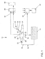
- FIG. 1 1 shows a device, generally designated 10, for measuring the temperature of a catalytic converter 12 through which an exhaust gas of an internal combustion engine flows or flows.
- the device 10 is part of a dynamic engine test bench for internal combustion engines 14, not shown in detail.
- the catalytic converter 12 is located in an exhaust gas line 16 of the internal combustion engine 14 arranged and acted upon by the exhaust gas 18.
- the catalytic converter 12 comprises a housing 20 with an inlet connection 22 for the untreated exhaust gas 18 and an outlet connection 24 for the catalytically treated exhaust gas 18.
- the catalyst support 26 is arranged, which is coated with a catalytically active coating (the so-called washcoat) is.
- a catalytically active coating (the so-called washcoat) is.
- it is a metal catalyst carrier, which is typically designed as a wound catalyst.
- a metal foil carrying the catalytically active coating is provided as a catalyst winding and fitted gas-tight into the housing 20.
- metal catalyst support and ceramic support so-called monoliths or the like can be used.
- the catalyst support 26 has a first end face 28, via which the exhaust gas 18 flows into the catalyst support 26, and a second end face 30, via which the catalytically treated exhaust gas 18 flows.
- the internal combustion engine 14 is associated with an engine controller 32, by means of which the working mode of the internal combustion engine 14 influencing operating parameters, such as ignition angle, throttle position, injection timing, fuel quantities to be injected, valve timing or the like, can be specified. These parameters are usually dependent on a current operating point, such as engine load or Motor speed specified, with stored maps are used. Furthermore, the engine controller 32 may also include control algorithms that cause coordination of the maps as well as the control of certain processes. The engine controller 32 cooperates with a transmission control unit 34, so that the engine controller 32 and the operating parameters of a - FIG. 1 not shown - transmission of the internal combustion engine 14 are known. Other operating parameters, such as signals from gas sensors of the exhaust system, are also included in the engine controller 32nd
- the device 10 further comprises an image recording device 36, which is preferably designed as a near-infrared thermographic camera 38.
- An objective 40 is directed onto the end face 30 of the catalyst winding 26 via an optical window 42, for example made of sapphire glass.
- the end face 30 or at least part of the end face 30 thus forms a measuring surface for measuring the temperature by means of the image recording device 36, as will be explained in more detail below.
- the device 10 comprises only one image recording device 36 which is associated with the end face 30.
- a further image recording device 36 may be provided which is associated with the end face 28.
- the measuring surface may also be formed by an arbitrarily placed sectional surface of the catalyst carrier 26.
- a catalyst can be prepared with an obliquely cut measuring surface or cut into a plurality of carrier blocks, so that there are measuring surfaces between two carrier blocks and thus temperatures at different depths of the catalyst carrier 26 can be determined.
- the image recording device 36 is connected to an evaluation device 44.
- the evaluation device 44 is associated with a calibration 46 which is connected to at least one temperature sensor (thermocouple) 48, which is introduced in a range of O to 2 mm from the end face 30 (and / or end face 28) in the axial direction in the catalyst winding 26 ,
- the thermocouple 48 is inserted into the cells or channels of the carrier 26 and the cell exit, for example, closed with ceramic adhesive to prevent flow through the cells with exhaust gas.
- the evaluation device 44 and the calibration 46 are connected to a storage means 50.
- FIG. 2 shows the arrangement of a catalyst 12 within the device 10 according to a further embodiment in longitudinal section, wherein the same parts as in FIG. 1 provided with the same reference numerals and are not explained again.
- the two catalyst carriers 26 arranged inside the housing 20 are assigned two image recording devices 36 designed as near-infrared thermographic cameras 38.
- Two optical (IR-transparent) windows 42 are provided in the housing 20 of the catalytic converter 12, by means of which a thermographic observation of the end surfaces 28 and 30 is possible.
- the optical window 42 consist for example of a Sapphire crystal or other IR-transparent material.
- the thermocouples (temperature sensors) 48 which are connected to the calibration 46 via signal lines 54 indicated here, are integrated in the end face 28 in the area of the measuring surface 52.
- the thermocouples 48 serve to calibrate the thermographic cameras 38 and for comparison purposes.
- the in the FIGS. 1 and 2 illustrated device 10 has the following function:
- the internal combustion engine 14 is driven in predetermined dynamic test cycles.
- a control of the internal combustion engine 14 via the engine controller 32 wherein operating parameters of the internal combustion engine 14 are set, which were obtained from test drives of a motor vehicle with a corresponding internal combustion engine 14 used on the test bench.
- the exhaust gas line 16 is acted upon by the exhaust gas 18, which has a temperature and pollutant composition dependent on the set operating parameters of the internal combustion engine 14.
- the exhaust gas 18 strikes the end face 28 of the catalyst support 26, flows through the catalyst support 26 and exits again on the end face 30.
- the measuring surface 52 of the end faces 28, 30 is scanned and recorded an image sequence.
- individual images are recorded with the appropriate repetition frequency, which together result in the image sequence.
- the corresponding digital signals supplied by the camera 38 are supplied to the evaluation device 44.
- the intensity of the thermal radiation of the catalyst carrier 26 in the region of the measuring surface is assigned a corresponding solid-state temperature. In this way, maximum temperature loads and real temporal temperature changes (transients) can be determined.
- the actual solid-state temperatures of the catalyst carrier 26 are determined for the engine operating points that have been started and stored as a function of the operating point.
- the temperature measurement is preferably synchronized with the current operating point by triggering.
- a 5V trigger signal output from the test stand is used to trigger the temperature detection.
- the assignment of the measured catalyst temperatures to the operating parameters is stored for each operating situation started on the engine test bench.
- the determined operating parameters are stored depending on the operating point in maps or characteristic curves, which are adjusted in accordance with limits not to be exceeded for the absolute catalyst temperature and for critical positive and negative temperature transients so that in a similar operating situation measured on the test bench increased thermal load does not occur.
- This adapted and stored in the engine control maps is accessed in real vehicle operation to adjust the required operating parameters depending on a requested by a driver by accelerator torque. If, for example, critical temperature loads of the carrier 26 occur on the engine test bench during ignition angle reductions during switching operations of an automatic transmission, the maps and / or control algorithms used for controlling the automatic switching operations are adapted such that the thermal load in the actual vehicle operation is reduced or avoided.
- the calibration of the signals output by the camera 38 that is, the assignment of the measured intensity to actual solid body temperatures is based on stationary engine operating points of the internal combustion engine 14.
- the internal combustion engine 14 is driven at a defined operating point until the catalyst 12 sets an equilibrium temperature. This temperature is over the Temperature sensors 48 measured and communicated to the calibration 46.
- the image sequences of the measuring surface 52 are recorded by means of the camera 38 during this calibration phase, so that an exact assignment to a defined temperature on the surface 28 can take place in accordance with the recorded intensity.
- the assignment of the temperature to the measured intensity is stored in a characteristic curve in the memory 50.
- This calibration of the camera 38 can take place in fixed cycles, for example, before a measurement cycle and / or after a measurement cycle. As a result, the optical measurement by means of the camera 38 influencing disturbing factors, such as contamination (sooting) of the optical window 42 are eliminated.
- the near infrared range is particularly suitable, while for the investigation in the low temperature range (cold start effects) the middle infrared range (MIR) is more sensitive.
- averaging of the measured values can take place.
- Corresponding to the repetition frequency of the camera 38 results in a number of measured values per second.
- an averaging for example from a measurement frequency of 50 Hz to a frequency of 10 Hz, an average value is formed for the selected number of measurements.
- the system according to the invention also allows a very good spatial resolution over the entire measuring surface by recording a two-dimensional intensity profile. As a result, local temperature peaks occurring as a result of inhomogeneous flow of the catalyst through the exhaust gas can be detected and suppressed.
- FIGS. 3 to 15 show the curves of various parameters and operating parameters of the internal combustion engine 14 in various struck on the transient test bench operating situations.
- the temperature of the inlet end surface 28 of the catalyst support 26 was determined thermographically with the thermographic camera 38 and for comparison with a conventional temperature sensor 48, which was located in the immediate vicinity of the thermographically evaluated area.
- the exhaust gas temperature was arranged by means of a temperature sensor arranged upstream of the catalytic converter 12 (in FIG. 1 and 2 not shown).
- the concentration of unburned hydrocarbons HC was determined by the fast FID measurement technique (flame ionization detection).
- a gas sensor also not shown, was arranged upstream of the catalytic converter 12.
- the same reference numerals are used for the same measurands.
- FIG. 3 shows results obtained with multiple ignition misfires at full load operation of the engine 14.
- the ignition of a cylinder was exposed at periodic intervals over a period of about 1 s.
- Curve 60 shows the course of the temperature of catalyst support 26 determined by means of thermography, measured in the middle region of catalyst end face 28.
- Curve 62 shows the temperature profile measured with temperature sensor 48 in the middle of end face 28.
- Curve 64 shows the exhaust gas temperature upstream of catalytic converter 12 and curve 66 shows the curve of the HC concentration upstream of the catalytic converter 12.
- the unburned hydrocarbons are catalytically converted in the catalyst 12, whereby temporary exothermic afterburning causes temperature peaks thermographically observed (curve 60).
- the catalyst temperature starting from a base level at about 870 ° C., rises in each case to over 1000 ° C. in the short term. The half-widths of these temperature peaks are in the range of about 400 to 500 ms.
- periodic cooling of the exhaust gas occurs (curve 64). It is noticeable that no temperature increase is detected by the conventional temperature measurement on the catalyst end face 28 with the thermocouple 48 (curve 62). Rather, after each misfire even a slight cooling is determined, which is caused by the cooler exhaust gas (curve 64).
- thermocouples are unable to detect short-term temperature events that do not result in heating of the thermocouple.
- FIG. 4 shows a similar series of measurements as FIG. 3 , but in each case at intervals of about 2 s, only a single misfire of a cylinder was caused, which corresponds to an event occurring at 50 Hz. The individual misfires lead to an increase in the HC concentration from 700 ppm to about 2000 ppm.
- a temperature increase of the end face 28 from 870 to more than 890 ° C is thermographically registered (curve 60). These temperature peaks, which have a half-width of less than 100 ms, are not registered by the thermocouple arranged on the catalyst end face (curve 62).
- FIGS. 3 and 4 make it clear that both multiple and single sparking misfires lead to a critical short-term increase in the temperature of the catalyst carrier 26. If such misfires occur in full load operation at anyway very high catalyst temperatures, there is a risk of the catalyst becoming heated above the permissible maximum temperature. However, at least just as damaging is the thermal cycling that occurs here with very high heating and cooling rates, whereby the (negative) cooling rate is to be regarded as much more critical than the (positive) heating rate. While hitherto short-term dynamic misfires have been underestimated due to the inadequate detection of the true catalyst temperature in terms of their damage potential, the present invention provides to adjust the engine control so that misfires are more effectively suppressed in full load operation.
- the air was injected between about 8 and 9 s and between 18 and 19 s.
- the exhaust gas is diluted in front of the catalyst by the air injection and the HC concentration thus decreases, there is a short-term increase in temperature of the catalyst by about 70 K.
- the temperature increase is due to the exothermic afterburning of the excess in the rich exhaust gas hydrocarbons with the blown Attributed oxygen.
- the half width of the thermographically determined temperature peaks of about 500 to 700 ms is sufficient to be registered by the thermocouple.
- the absolute temperature change is indicated by about 75% too low and with a certain delay.
- FIG. 6 shows measurement results obtained with a one-time retardation of ignition timing (retardation) by 6 ° CA with otherwise constant operating parameters in partial load engine operation.
- FIGS. 7 to 9 show dynamometer results of dynamic driving cycles.
- the operating parameters necessary for controlling the driving cycles were determined in the transient operation of a vehicle with automatic shifting in the inner track cycle.
- the figures show the influence of Zündwinkellessness notion for the purpose of torque reduction in automatic switching operation. Shown is the temperature of the catalyst detected thermographically at a measuring frequency of 5 Hz (curve 60), the catalyst temperature also measured at the end face with a thermosensor (curve 62) and the HC concentration present upstream of the catalyst (curve 66, only in FIG FIG. 8 ).
- FIG. 9 also shows the temporal catalyst temperature changes (temperature transients) determined by thermography (curve 60 ') as well as thermocouple (curve 62').
- the curves 60 'and 62' were formed by forming the first derivative of the curves 60 and 62, respectively Figure 8 and averaged to 1 Hz for better comparability and smoothing.
- the gear shift to the next higher gear is accompanied by a retraction of the ignition timing in order to achieve the fastest possible and precise reduction of the torque at the gear change due to the deterioration of the engine efficiency.
- a retardation of the ignition angle to a maximum of 3.75 ° kW after ZOT took place.
- FIG. 7 at about 638.5 s and in the FIGS. 8 and 9 at about 97 s ago.
- FIGS. 10 to 12 show results obtained on the test bench in dynamic driving cycles, determined on a high-speed train with a vehicle with manual transmission.
- FIG. 10 are shown thermographically determined with a measuring frequency of 50 Hz Catalyst temperature (curve 60), the thermocouple determined catalyst temperature (curve 62), the exhaust gas HC concentration (curve 66), the speed (curve 70) and the throttle opening (curve 74).
- time interval three switching operations, namely at 115 seconds, 125 and 141.
- a torque reduction takes place during the switching process by the driver himself by this briefly retracting the accelerator pedal.
- the throttle closes (curve 74).
- FIG. 11 that made the FIG. 10 obtained temperature transient - formed from the first derivatives of the curves 60 and 62 - shows heating rates in the course of the three switching operations of over +8000 K / min and cooling rates of about -7000 K / min. Both curves were averaged to 1 Hz for better comparability.
- FIG. 12 shows thermographic and thermocouple temperature transients of the same series of measurements.
- thermographically determined catalyst temperature (curve 60 ) averaged over 10 Hz is shown here in addition to the curves averaged at 1 Hz, and it is clear that the averaging to 10 Hz with respect to the 1 Hz averaging although with A worse signal-to-noise ratio, however, is also associated with a loss of information at 1 Hz, and in particular the true intensities are greatly smoothed.
- FIG. 13 shows a measurement in the dynamic drive cycle at a transition from full load to overrun.
- curve 78 shows the thermographically recorded temperature values at the hottest point of the end face 28, which always lie above those of the center.
- curve 78 shows the advantage of the spatially resolved temperature detection, which allows a consideration of the total catalyst area.
- the purpose of the dashpot function which is usually used to reduce the fuel supply in overrun mode, is to discharge a wall film of the cylinders formed by unburned fuel in such a way that it can still be burnt.
- the wall film demolition is modulated and so much fuel supplied that a mixture that is just ignitable is formed.
- the dashpot function is intended to prevent the unburned ejected fuel wall film burns on the catalyst and thus leads to an increased temperature load. As at the curve 66 of FIG. 12 can be seen, but this succeeds only incomplete. There is a certain output of unburned hydrocarbons HC and their post-combustion at the catalyst, causing there exothermic temperature peaks.
- Curve 78 which shows the thermographically determined catalyst temperature at the hottest point of the end face, shows that catalyst temperatures of up to 980 ° C occur in this case. According to the invention here is the opportunity to optimize the dashpot function so that these temperature peaks are avoided on the catalyst.
- FIGS. 14 and 15 show the influence of a lambda reduction (lambda enrichment) in the dynamic driving cycle in a transition from thrust to full load operation.
- the fuel cut is canceled and set a predetermined air-fuel mixture lambda.
- curve 68 comes in FIG. 14 from the positive infinite and adjusts itself to the given value. Due to the onset of combustion, there is a very rapid heating of the catalyst, as can be seen in the course of the thermographically determined temperature curve 60. Due to inertia, the temperature profile determined with the thermocouple follows the true temperature (curve 62). In order to protect the catalyst from excessive thermal stress in such situations, it is common to lower the combustion lambda more than necessary.
- FIG. 15 shows from the curves 60 and 62 of FIG. 14 determined temperature transients. Both curves were averaged to 1 Hz.
- the temperature detection according to the invention of catalysts with high time resolution and high spatial resolution allows a more accurate conception of the exact temperature behavior in certain operating situations.
Landscapes
- Engineering & Computer Science (AREA)
- Chemical & Material Sciences (AREA)
- Combustion & Propulsion (AREA)
- Mechanical Engineering (AREA)
- General Engineering & Computer Science (AREA)
- Chemical Kinetics & Catalysis (AREA)
- Physics & Mathematics (AREA)
- General Physics & Mathematics (AREA)
- Exhaust Gas After Treatment (AREA)
Claims (18)
- Procédé d'adaptation d'une commande de moteur (32) en ce qui concerne une charge thermique d'un catalyseur (12), dans lequel on fait fonctionner un moteur à combustion interne (14) en une marche de test stationnaire et/ou non stationnaire dans des cycles de test prédéterminés et on détermine une température de catalyseur en fonction du point de fonctionnement et, en présence d'une charge thermique accrue du catalyseur (12), on produit au moins une mesure applicative dans la commande de moteur (32) pour une utilisation ultérieure dans un fonctionnement réel du véhicule, de telle manière que, lors d'un fonctionnement analogue du moteur à combustion interne (14) dans un fonctionnement réel du véhicule, cette charge thermique accrue soit évitée, caractérisé en ce que, dans la marche de test, on détermine la température du catalyseur par thermographie pour un saut de température (ΔT) sur une plage de 20K à 150K avec une température initiale dans une plage de 500°C à 950°C, avec au moins une des résolutions temporelles suivantes:- après 10 ms, on détecte au moins 10 % du saut de température,- après 100 ms, on détecte au moins 20 % du saut de température,- après 500 ms, on détecte au moins 35 % du saut de température,- après 1000 ms, on détecte au moins 50 % du saut de température.
- Procédé selon la revendication 1, caractérisé en ce que l'on détecte la température du catalyseur avec au moins une des résolutions temporelles suivantes:- après 10 ms, on détecte au moins 15 % du saut de température,- après 100 ms, on détecte au moins 30 % du saut de température,- après 500 ms, on détecte au moins 50 % du saut de température,- après 1000 ms, on détecte au moins 70 % du saut de température.
- Procédé selon l'une quelconque des revendications précédentes, caractérisé en ce que l'on détecte la température du catalyseur avec des vitesses de chauffage et/ou des vitesses de refroidissement d'au moins |100K/s|, en particulier d'au moins |200K/s|, de préférence d'au moins |1000K/s| avec au moins une des résolutions temporelles.
- Procédé selon l'une quelconque des revendications précédentes, caractérisé en ce que l'on résout des pics de température temporaires de la température du catalyseur avec une largeur à mi-hauteur d'au plus 1000 ms, en particulier d'au plus 500 ms, de préférence d'au plus 250 ms, dans lequel on détecte au moins 50 % du saut de température.
- Procédé selon l'une quelconque des revendications précédentes, caractérisé en ce que l'on détecte la température du catalyseur avec une fréquence d'au moins 10 Hz, en particulier d'au moins 50 Hz.
- Procédé selon la revendication 5, caractérisé en ce que l'on calcule la moyenne des valeurs de mesure détectées sur un plus petit nombre de valeurs de mesure par seconde.
- Procédé selon l'une quelconque des revendications précédentes, caractérisé en ce que, dans la marche de test, on détermine la température du catalyseur sur une surface de mesure (52) du catalyseur (12) d'au moins 4 cm2 disposée essentiellement transversalement à la direction d'écoulement des gaz d'échappement, dans lequel on détermine la charge thermique à l'intérieur de la surface de mesure (52) en au moins deux points de mesure avec résolution de position.
- Procédé selon la revendication 7, caractérisé en ce que l'on détermine la température du catalyseur sur une surface de mesure (52) d'au moins 6,5 cm2, de préférence d'au moins 9 cm2.
- Procédé selon l'une quelconque des revendications 7 ou 8, caractérisé en ce que l'on détermine la température du catalyseur en au moins cinq, de préférence en au moins 20 points de mesure.
- Procédé selon l'une quelconque des revendications précédentes, caractérisé en ce que l'on détermine la température du catalyseur par thermographie infrarouge dans le domaine de l'infrarouge proche ou moyen.
- Procédé selon l'une quelconque des revendications précédentes, caractérisé en ce que l'on détermine comme charge thermique la température de corps solide réelle d'un support du catalyseur (12) séparément de la température d'un produit d'imprégnation.
- Procédé selon l'une quelconque des revendications précédentes, caractérisé en ce que l'on détermine la charge thermique sur une surface d'entrée et/ou sur une surface de sortie et/ou sur d'autres surfaces du catalyseur.
- Procédé selon l'une quelconque des revendications précédentes, caractérisé en ce que, dans au moins une des situations de fonctionnement suivantes, on détermine la température de catalyseur du catalyseur (12) en marche stationnaire et/ou non stationnaire:- situation à haut risque pour ratés d'allumage simples ou multiples,- déplacements de l'angle d'allumage;- opérations de changement du rapport avec transmission automatiques et manuelles,- passages de la marche à pleine charge à la marche en poussée et/ou de la marche en poussée à la marche à pleine charge,- baisses de lambda à partir de lambda riche comme mesure pour la protection des pièces,- insufflations d'air dans le collecteur en cas de lambda riche,- oscillations de lambda.
- Procédé selon l'une quelconque des revendications précédentes, caractérisé en ce que, pour chaque situation de fonctionnement parcourue en fonctionnement stationnaire et/ou non stationnaire, on détermine les paramètres de fonctionnement du moteur à combustion interne (14) déterminants pour la variation de la température du catalyseur (12) en même temps que les températures de catalyseur déterminées.
- Procédé selon l'une quelconque des revendications précédentes, caractérisé en ce que ladite au moins une mesure applicative, en particulier les diagrammes caractéristiques et/ou les algorithmes de commande, est conçue de telle manière qu'une température absolue critique du catalyseur (12), spécifique au catalyseur, et/ou une vitesse de chauffage critique et/ou une vitesse de refroidissement critique soit évitée.
- Procédé selon l'une quelconque des revendications précédentes, caractérisé en ce que l'on effectue un calibrage d'un dispositif de mesure utilisé pour la détermination de la charge thermique, en mesurant dans des conditions d'équilibre la charge thermique du catalyseur (12) en même temps au moyen du dispositif de mesure utilisé et au moyen d'un système de mesure calibré et en corrélant un signal du dispositif de mesure thermographique avec la température mesurée avec le système de mesure calibré.
- Procédé de commande d'un moteur à combustion interne (14), avec au moins un catalyseur (12) placé en aval, dans lequel on prédétermine des paramètres de fonctionnement pour la commande du moteur à combustion interne (14) en fonction d'une situation de fonctionnement actuelle au moyen de moyens applicatifs d'une commande de moteur (32), en particulier au moyen de diagrammes caractéristiques et/ou d'algorithmes, de telle manière qu'une charge thermique accrue du catalyseur (12) soit évitée, et dans lequel les moyens applicatifs de la commande de moteur (32) sont déterminés par un procédé selon l'une quelconque des revendications 1 à 6 et 10 à 16.
- Commande de moteur (32) d'un moteur à combustion interne (14) avec au moins un catalyseur (12) placé en aval, dans laquelle la commande de moteur (32) comprend des moyens applicatifs, en particulier des diagrammes caractéristiques et/ou des algorithmes, avec lesquels le moteur à combustion interne (14) peut être commandé de telle manière que, dans un fonctionnement du moteur à combustion interne (14), une charge thermique accrue dudit au moins un catalyseur (12) soit évitée, et dans laquelle les moyens applicatifs sont obtenus par un procédé selon l'une quelconque des revendications 1 à 6 et 10 à 16.
Priority Applications (1)
| Application Number | Priority Date | Filing Date | Title |
|---|---|---|---|
| EP10170144.9A EP2253825B1 (fr) | 2002-07-31 | 2003-07-30 | Procédé d'adaptation applicative d'une commande de moteur et commande de moteur fabriqué selon ledit procédé |
Applications Claiming Priority (5)
| Application Number | Priority Date | Filing Date | Title |
|---|---|---|---|
| DE10235094 | 2002-07-31 | ||
| DE10235094 | 2002-07-31 | ||
| DE10241052 | 2002-08-30 | ||
| DE10241052 | 2002-08-30 | ||
| PCT/EP2003/008433 WO2004013474A1 (fr) | 2002-07-31 | 2003-07-30 | Procede d'adaptation applicative d'une commande de moteur et commande de moteur obtenue selon ledit procede |
Related Child Applications (2)
| Application Number | Title | Priority Date | Filing Date |
|---|---|---|---|
| EP10170144.9A Division EP2253825B1 (fr) | 2002-07-31 | 2003-07-30 | Procédé d'adaptation applicative d'une commande de moteur et commande de moteur fabriqué selon ledit procédé |
| EP10170144.9A Division-Into EP2253825B1 (fr) | 2002-07-31 | 2003-07-30 | Procédé d'adaptation applicative d'une commande de moteur et commande de moteur fabriqué selon ledit procédé |
Publications (2)
| Publication Number | Publication Date |
|---|---|
| EP1527263A1 EP1527263A1 (fr) | 2005-05-04 |
| EP1527263B1 true EP1527263B1 (fr) | 2012-09-19 |
Family
ID=31189301
Family Applications (2)
| Application Number | Title | Priority Date | Filing Date |
|---|---|---|---|
| EP10170144.9A Expired - Lifetime EP2253825B1 (fr) | 2002-07-31 | 2003-07-30 | Procédé d'adaptation applicative d'une commande de moteur et commande de moteur fabriqué selon ledit procédé |
| EP03766367A Expired - Lifetime EP1527263B1 (fr) | 2002-07-31 | 2003-07-30 | Procede d'adaptation applicative d'une commande de moteur et commande de moteur obtenue selon ledit procede |
Family Applications Before (1)
| Application Number | Title | Priority Date | Filing Date |
|---|---|---|---|
| EP10170144.9A Expired - Lifetime EP2253825B1 (fr) | 2002-07-31 | 2003-07-30 | Procédé d'adaptation applicative d'une commande de moteur et commande de moteur fabriqué selon ledit procédé |
Country Status (3)
| Country | Link |
|---|---|
| EP (2) | EP2253825B1 (fr) |
| DE (1) | DE10335370B4 (fr) |
| WO (1) | WO2004013474A1 (fr) |
Families Citing this family (11)
| Publication number | Priority date | Publication date | Assignee | Title |
|---|---|---|---|---|
| DE102005019940A1 (de) * | 2005-04-29 | 2005-11-24 | Daimlerchrysler Ag | Verfahren zum Betreiben einer Brennkraftmaschine und dessen Verwendung |
| DE112006000952A5 (de) * | 2005-05-03 | 2008-02-14 | Avl List Gmbh | Verfahren zur Erkennung von reaktiven Gasanteilen |
| AT502911B1 (de) * | 2005-06-09 | 2008-06-15 | Avl List Gmbh | Verfahren zur erkennung von reaktiven gasanteilen |
| DE102006007417B4 (de) * | 2006-02-17 | 2012-08-09 | Continental Automotive Gmbh | Verfahren und Vorrichtung zum Betreiben einer Brennkraftmaschine |
| DE102008026236A1 (de) | 2008-05-28 | 2009-12-03 | Volkswagen Ag | Verfahren und Vorrichtung zur Ermittlung einer Temperatur einer Abgasnachbehandlungskomponente |
| DE102010002775A1 (de) | 2010-03-11 | 2011-09-15 | Robert Bosch Gmbh | Verfahren zum Betreiben von Katalysatoren und/oder Abgassonden |
| SE535930C2 (sv) * | 2010-06-21 | 2013-02-26 | Scania Cv Ab | Förfarande och anordning för undvikande av överhettning hos en doseringsenhet vid ett SCR-system |
| CN101936775B (zh) * | 2010-07-27 | 2011-11-02 | 中国计量学院 | 风筒出风口温度场的组合式测量装置及方法 |
| DE102012006249A1 (de) * | 2012-03-28 | 2013-10-02 | Emitec Denmark A/S | Fördereinheit für ein flüssiges Additiv mit einem Temperatursensor |
| CN109029779B (zh) * | 2018-04-28 | 2020-02-14 | 华映科技(集团)股份有限公司 | 一种实时人体温度快速侦测法 |
| CN112539939B (zh) * | 2020-12-22 | 2022-03-22 | 中联恒通机械有限公司 | 一种相变发动机尾焰温度测试装置及控制方法 |
Family Cites Families (20)
| Publication number | Priority date | Publication date | Assignee | Title |
|---|---|---|---|---|
| DE3812020A1 (de) | 1988-04-11 | 1989-10-26 | Interatom | Einrichtung zur beruehrungslosen temperaturmessung |
| US4854162A (en) * | 1988-06-27 | 1989-08-08 | Ford Motor Company | Method of locating friction generating defects in a multiple bearing assembly |
| DE4103747A1 (de) * | 1991-02-07 | 1992-08-13 | Emitec Emissionstechnologie | Verfahren und vorrichtung zur steuerung eines verbrennungsmotors unter einbeziehung der aktuellen temperatur eines nachgeschalteten katalysators |
| ES2048592T3 (es) * | 1990-03-19 | 1994-03-16 | Emitec Emissionstechnologie | Procedimiento y dispositivo para el control del funcionamiento de un catalizador de una maquina motriz de combustion interna. |
| DE4027207A1 (de) | 1990-08-28 | 1992-03-05 | Emitec Emissionstechnologie | Ueberwachung der katalytischen aktivitaet eines katalysators im abgassystem einer brennkraftmaschine |
| DE4032721A1 (de) * | 1990-10-15 | 1992-04-16 | Emitec Emissionstechnologie | Ueberwachung der funktion eines von einem katalysierbaren fluid durchstroembaren katalysators |
| DE4038829A1 (de) * | 1990-12-05 | 1992-06-11 | Emitec Emissionstechnologie | Ermittlung einer reaktionszone in einem katalysator |
| DE4244712C2 (de) * | 1992-02-14 | 1996-09-05 | Degussa | Beschichtungsdispersion zur Herstellung von kalysefördernden Überzügen auf einem inerten, strukturverstärkenden Körper |
| DE4319924A1 (de) * | 1993-06-16 | 1994-12-22 | Emitec Emissionstechnologie | Verfahren zur Überwachung der Funktion eines katalytischen Konverters |
| DE4228536A1 (de) * | 1992-08-27 | 1994-03-03 | Roth Technik Gmbh | Verfahren zur Überwachung der Funktionsfähigkeit von Katalysatoren in Abgasanlagen |
| DE4308661A1 (de) * | 1993-03-18 | 1994-09-22 | Emitec Emissionstechnologie | Verfahren und Vorrichtung zur Funktionsüberwachung eines katalytischen Konverters |
| US5475223A (en) * | 1994-04-25 | 1995-12-12 | Ford Motor Company | System for monitoring exhaust gas composition |
| DE19648427C2 (de) | 1996-11-22 | 2001-10-18 | Siemens Ag | Verfahren zur Regelung der Temperatur eines Katalysators |
| US6202406B1 (en) * | 1998-03-30 | 2001-03-20 | Heralus Electro-Nite International N.V. | Method and apparatus for catalyst temperature control |
| DE19832833C2 (de) | 1998-07-21 | 2002-01-31 | Fraunhofer Ges Forschung | Verfahren zur thermographischen Untersuchung eines Werkstückes und Vorrichtung hierfür |
| DE19833596A1 (de) | 1998-07-25 | 2000-02-10 | Joerg Kaiser | Vorrichtung zur Messung von Oberflächentemperaturen |
| DE19931223C2 (de) * | 1999-07-06 | 2002-10-31 | Siemens Ag | Verfahren zum Erkennen und Aufrechterhalten der Betriebsbereitschaft eines NOx-Speicherkatalysators |
| DE10020199A1 (de) | 2000-04-25 | 2001-10-31 | Inst Innovative Technologien T | Temperaturmeßeinrichtung |
| DE10103689A1 (de) * | 2001-01-26 | 2002-08-01 | Sandvoss Rolf | Thermographieverfahren |
| DE10124550B4 (de) * | 2001-05-19 | 2005-01-05 | Daimlerchrysler Ag | Sensor und Verfahren zur Überwachung und Steuerung von Katalysatoren, insbesondere von Kraftfahrzeugkatalysatoren |
-
2003
- 2003-07-30 DE DE10335370A patent/DE10335370B4/de not_active Expired - Fee Related
- 2003-07-30 EP EP10170144.9A patent/EP2253825B1/fr not_active Expired - Lifetime
- 2003-07-30 WO PCT/EP2003/008433 patent/WO2004013474A1/fr not_active Ceased
- 2003-07-30 EP EP03766367A patent/EP1527263B1/fr not_active Expired - Lifetime
Also Published As
| Publication number | Publication date |
|---|---|
| EP2253825A3 (fr) | 2016-07-27 |
| WO2004013474A1 (fr) | 2004-02-12 |
| EP1527263A1 (fr) | 2005-05-04 |
| EP2253825A2 (fr) | 2010-11-24 |
| DE10335370A1 (de) | 2004-02-26 |
| EP2253825B1 (fr) | 2018-11-07 |
| DE10335370B4 (de) | 2013-06-27 |
Similar Documents
| Publication | Publication Date | Title |
|---|---|---|
| EP1527263B1 (fr) | Procede d'adaptation applicative d'une commande de moteur et commande de moteur obtenue selon ledit procede | |
| DE60124807T2 (de) | An-Bord-Fehlzündung und unvollständige Verbrennung, Erfassung und Zündverzögerungs-Steuerung mit Zylinderdruckerfassung | |
| DE602005005849T2 (de) | Vorrichtung und verfahren zur bestimmung der von einem dieselmotor eines kraftfahrzeuges ausgestossenen nox-menge und diagnose- sowie motorverwaltungssystem mit einer derartigen vorrichtung | |
| EP0587836A1 (fr) | Procede et dispositif pour evaluer l'aptitude au fonctionnement d'un catalyseur. | |
| DE10111586A1 (de) | Verfahren zum Betrieb von Brennkraftmaschinen | |
| DE102008002261A1 (de) | Verfahren und Vorrichtung zur Ermittlung eines oder mehrerer Brennbeginne in einem Zylinder eines Verbrennungsmotors aus einem bereitgestellten Zylinderdruckverlauf | |
| DE102008005110A1 (de) | Verfahren und Steuerung zum Betreiben und Einstellen einer Lambda-Sonde | |
| DE112009004665T5 (de) | Katalysatoranormalitätsdiagnosevorrichtung | |
| DE10309422B4 (de) | Verfahren und Vorrichtung zur Kalibrierung eines NOx-Sensors | |
| EP1998032B1 (fr) | Procédé d'évaluation de l'état d'un mélange air/carburant | |
| EP1527264B1 (fr) | Méthode pour la génération de courbes caractéristiques ou de jeux de telles courbes pour le contrôle de moteurs à combustion interne | |
| DE102011087000B4 (de) | Vorrichtung zur Messung wenigstens einer Abgaskomponente in einem Abgaskanal eines Verbrennungsprozesses | |
| DE102014226757B3 (de) | Verfahren und Vorrichtung zum Erkennen von Glühzündungen bei einer fremdgezündeten Brennkraftmaschine | |
| DE4042025C2 (de) | Vorrichtung und Verfahren zur Auswertung des Verbrennungszustands in einer Brennkraftmaschine | |
| DE19608340A1 (de) | Verfahren zur Bestimmung, ob vor dem Starten einer Brennkraftmaschine eine Brennkraftmaschinen-Vorheizung erfolgt ist | |
| DE102014007537A1 (de) | Verfahren und Vorrichtung zum Ermitteln des Erwärmungsverhaltens eines Arbeitskolbens | |
| DE3840248C2 (fr) | ||
| DE10318463B4 (de) | Verfahren und Vorrichtung zum abgasseitigen Erfassen von Temperaturen an Verbrennungskraftmaschinen | |
| EP1524421B1 (fr) | Procédé et dispositif pour protéger un turbocompresseur | |
| DE102016221776B4 (de) | Verfahren zum Bewerten einer Zündeinrichtung für eine Brennkraftmaschine | |
| DE10332629B4 (de) | Verfahren zur Überwachung einer Breitbandsonde | |
| DE19523987C2 (de) | Abgassensor | |
| DE102014223864A1 (de) | Verfahren zur Erkennung eines Spannungsoffsets zumindest in einem Bereich bei einer Spannungs-Lambda-Kennlinie | |
| DE102009046763A1 (de) | Verfahren zum Betreiben einer Brennkraftmaschine, Vorrichtung zum Betreiben einer Brennkraftmaschine, Computerprogramm sowie Computer-Programmprodukt | |
| AT520434B1 (de) | Verfahren zur erkennung und detektion von vorzündungsereignissen |
Legal Events
| Date | Code | Title | Description |
|---|---|---|---|
| PUAI | Public reference made under article 153(3) epc to a published international application that has entered the european phase |
Free format text: ORIGINAL CODE: 0009012 |
|
| 17P | Request for examination filed |
Effective date: 20050228 |
|
| AK | Designated contracting states |
Kind code of ref document: A1 Designated state(s): AT BE BG CH CY CZ DE DK EE ES FI FR GB GR HU IE IT LI LU MC NL PT RO SE SI SK TR |
|
| RIN1 | Information on inventor provided before grant (corrected) |
Inventor name: DIEZEMANN, MATTHIAS Inventor name: BUECHNER, STEFAN |
|
| 17Q | First examination report despatched |
Effective date: 20070326 |
|
| GRAP | Despatch of communication of intention to grant a patent |
Free format text: ORIGINAL CODE: EPIDOSNIGR1 |
|
| RAP1 | Party data changed (applicant data changed or rights of an application transferred) |
Owner name: VOLKSWAGEN AKTIENGESELLSCHAFT |
|
| GRAS | Grant fee paid |
Free format text: ORIGINAL CODE: EPIDOSNIGR3 |
|
| GRAA | (expected) grant |
Free format text: ORIGINAL CODE: 0009210 |
|
| RIN1 | Information on inventor provided before grant (corrected) |
Inventor name: DIEZEMANN, MATTHIAS Inventor name: BUECHNER, STEFAN |
|
| AK | Designated contracting states |
Kind code of ref document: B1 Designated state(s): AT BE BG CH CY CZ DE DK EE ES FI FR GB GR HU IE IT LI LU MC NL PT RO SE SI SK TR |
|
| REG | Reference to a national code |
Ref country code: GB Ref legal event code: FG4D Free format text: NOT ENGLISH |
|
| REG | Reference to a national code |
Ref country code: CH Ref legal event code: EP |
|
| REG | Reference to a national code |
Ref country code: IE Ref legal event code: FG4D Free format text: LANGUAGE OF EP DOCUMENT: GERMAN |
|
| REG | Reference to a national code |
Ref country code: AT Ref legal event code: REF Ref document number: 576161 Country of ref document: AT Kind code of ref document: T Effective date: 20121015 |
|
| REG | Reference to a national code |
Ref country code: DE Ref legal event code: R096 Ref document number: 50314502 Country of ref document: DE Effective date: 20121115 |
|
| PG25 | Lapsed in a contracting state [announced via postgrant information from national office to epo] |
Ref country code: FI Free format text: LAPSE BECAUSE OF FAILURE TO SUBMIT A TRANSLATION OF THE DESCRIPTION OR TO PAY THE FEE WITHIN THE PRESCRIBED TIME-LIMIT Effective date: 20120919 Ref country code: CY Free format text: LAPSE BECAUSE OF FAILURE TO SUBMIT A TRANSLATION OF THE DESCRIPTION OR TO PAY THE FEE WITHIN THE PRESCRIBED TIME-LIMIT Effective date: 20120919 |
|
| REG | Reference to a national code |
Ref country code: NL Ref legal event code: VDEP Effective date: 20120919 |
|
| PG25 | Lapsed in a contracting state [announced via postgrant information from national office to epo] |
Ref country code: SE Free format text: LAPSE BECAUSE OF FAILURE TO SUBMIT A TRANSLATION OF THE DESCRIPTION OR TO PAY THE FEE WITHIN THE PRESCRIBED TIME-LIMIT Effective date: 20120919 Ref country code: GR Free format text: LAPSE BECAUSE OF FAILURE TO SUBMIT A TRANSLATION OF THE DESCRIPTION OR TO PAY THE FEE WITHIN THE PRESCRIBED TIME-LIMIT Effective date: 20121220 Ref country code: SI Free format text: LAPSE BECAUSE OF FAILURE TO SUBMIT A TRANSLATION OF THE DESCRIPTION OR TO PAY THE FEE WITHIN THE PRESCRIBED TIME-LIMIT Effective date: 20120919 |
|
| PG25 | Lapsed in a contracting state [announced via postgrant information from national office to epo] |
Ref country code: ES Free format text: LAPSE BECAUSE OF FAILURE TO SUBMIT A TRANSLATION OF THE DESCRIPTION OR TO PAY THE FEE WITHIN THE PRESCRIBED TIME-LIMIT Effective date: 20121230 Ref country code: NL Free format text: LAPSE BECAUSE OF FAILURE TO SUBMIT A TRANSLATION OF THE DESCRIPTION OR TO PAY THE FEE WITHIN THE PRESCRIBED TIME-LIMIT Effective date: 20120919 Ref country code: EE Free format text: LAPSE BECAUSE OF FAILURE TO SUBMIT A TRANSLATION OF THE DESCRIPTION OR TO PAY THE FEE WITHIN THE PRESCRIBED TIME-LIMIT Effective date: 20120919 Ref country code: CZ Free format text: LAPSE BECAUSE OF FAILURE TO SUBMIT A TRANSLATION OF THE DESCRIPTION OR TO PAY THE FEE WITHIN THE PRESCRIBED TIME-LIMIT Effective date: 20120919 Ref country code: RO Free format text: LAPSE BECAUSE OF FAILURE TO SUBMIT A TRANSLATION OF THE DESCRIPTION OR TO PAY THE FEE WITHIN THE PRESCRIBED TIME-LIMIT Effective date: 20120919 |
|
| PG25 | Lapsed in a contracting state [announced via postgrant information from national office to epo] |
Ref country code: PT Free format text: LAPSE BECAUSE OF FAILURE TO SUBMIT A TRANSLATION OF THE DESCRIPTION OR TO PAY THE FEE WITHIN THE PRESCRIBED TIME-LIMIT Effective date: 20130121 Ref country code: SK Free format text: LAPSE BECAUSE OF FAILURE TO SUBMIT A TRANSLATION OF THE DESCRIPTION OR TO PAY THE FEE WITHIN THE PRESCRIBED TIME-LIMIT Effective date: 20120919 |
|
| PLBE | No opposition filed within time limit |
Free format text: ORIGINAL CODE: 0009261 |
|
| STAA | Information on the status of an ep patent application or granted ep patent |
Free format text: STATUS: NO OPPOSITION FILED WITHIN TIME LIMIT |
|
| PG25 | Lapsed in a contracting state [announced via postgrant information from national office to epo] |
Ref country code: BG Free format text: LAPSE BECAUSE OF FAILURE TO SUBMIT A TRANSLATION OF THE DESCRIPTION OR TO PAY THE FEE WITHIN THE PRESCRIBED TIME-LIMIT Effective date: 20121219 Ref country code: DK Free format text: LAPSE BECAUSE OF FAILURE TO SUBMIT A TRANSLATION OF THE DESCRIPTION OR TO PAY THE FEE WITHIN THE PRESCRIBED TIME-LIMIT Effective date: 20120919 |
|
| 26N | No opposition filed |
Effective date: 20130620 |
|
| PG25 | Lapsed in a contracting state [announced via postgrant information from national office to epo] |
Ref country code: IT Free format text: LAPSE BECAUSE OF FAILURE TO SUBMIT A TRANSLATION OF THE DESCRIPTION OR TO PAY THE FEE WITHIN THE PRESCRIBED TIME-LIMIT Effective date: 20120919 |
|
| REG | Reference to a national code |
Ref country code: DE Ref legal event code: R097 Ref document number: 50314502 Country of ref document: DE Effective date: 20130620 |
|
| BERE | Be: lapsed |
Owner name: VOLKSWAGEN A.G. Effective date: 20130731 |
|
| PG25 | Lapsed in a contracting state [announced via postgrant information from national office to epo] |
Ref country code: MC Free format text: LAPSE BECAUSE OF FAILURE TO SUBMIT A TRANSLATION OF THE DESCRIPTION OR TO PAY THE FEE WITHIN THE PRESCRIBED TIME-LIMIT Effective date: 20120919 |
|
| REG | Reference to a national code |
Ref country code: CH Ref legal event code: PL |
|
| GBPC | Gb: european patent ceased through non-payment of renewal fee |
Effective date: 20130730 |
|
| REG | Reference to a national code |
Ref country code: IE Ref legal event code: MM4A |
|
| REG | Reference to a national code |
Ref country code: FR Ref legal event code: ST Effective date: 20140331 |
|
| PG25 | Lapsed in a contracting state [announced via postgrant information from national office to epo] |
Ref country code: GB Free format text: LAPSE BECAUSE OF NON-PAYMENT OF DUE FEES Effective date: 20130730 Ref country code: CH Free format text: LAPSE BECAUSE OF NON-PAYMENT OF DUE FEES Effective date: 20130731 Ref country code: LI Free format text: LAPSE BECAUSE OF NON-PAYMENT OF DUE FEES Effective date: 20130731 Ref country code: BE Free format text: LAPSE BECAUSE OF NON-PAYMENT OF DUE FEES Effective date: 20130731 |
|
| PG25 | Lapsed in a contracting state [announced via postgrant information from national office to epo] |
Ref country code: FR Free format text: LAPSE BECAUSE OF NON-PAYMENT OF DUE FEES Effective date: 20130731 |
|
| PG25 | Lapsed in a contracting state [announced via postgrant information from national office to epo] |
Ref country code: IE Free format text: LAPSE BECAUSE OF NON-PAYMENT OF DUE FEES Effective date: 20130730 |
|
| REG | Reference to a national code |
Ref country code: AT Ref legal event code: MM01 Ref document number: 576161 Country of ref document: AT Kind code of ref document: T Effective date: 20130730 |
|
| PG25 | Lapsed in a contracting state [announced via postgrant information from national office to epo] |
Ref country code: AT Free format text: LAPSE BECAUSE OF NON-PAYMENT OF DUE FEES Effective date: 20130730 |
|
| PG25 | Lapsed in a contracting state [announced via postgrant information from national office to epo] |
Ref country code: TR Free format text: LAPSE BECAUSE OF FAILURE TO SUBMIT A TRANSLATION OF THE DESCRIPTION OR TO PAY THE FEE WITHIN THE PRESCRIBED TIME-LIMIT Effective date: 20120919 |
|
| PG25 | Lapsed in a contracting state [announced via postgrant information from national office to epo] |
Ref country code: HU Free format text: LAPSE BECAUSE OF FAILURE TO SUBMIT A TRANSLATION OF THE DESCRIPTION OR TO PAY THE FEE WITHIN THE PRESCRIBED TIME-LIMIT; INVALID AB INITIO Effective date: 20030730 Ref country code: LU Free format text: LAPSE BECAUSE OF NON-PAYMENT OF DUE FEES Effective date: 20130730 |
|
| PGFP | Annual fee paid to national office [announced via postgrant information from national office to epo] |
Ref country code: DE Payment date: 20190731 Year of fee payment: 17 |
|
| REG | Reference to a national code |
Ref country code: DE Ref legal event code: R119 Ref document number: 50314502 Country of ref document: DE |
|
| PG25 | Lapsed in a contracting state [announced via postgrant information from national office to epo] |
Ref country code: DE Free format text: LAPSE BECAUSE OF NON-PAYMENT OF DUE FEES Effective date: 20210202 |