EP1527263B1 - Method for the applied adaptation of the control of a motor and control of a motor that is obtained according to said method - Google Patents
Method for the applied adaptation of the control of a motor and control of a motor that is obtained according to said method Download PDFInfo
- Publication number
- EP1527263B1 EP1527263B1 EP03766367A EP03766367A EP1527263B1 EP 1527263 B1 EP1527263 B1 EP 1527263B1 EP 03766367 A EP03766367 A EP 03766367A EP 03766367 A EP03766367 A EP 03766367A EP 1527263 B1 EP1527263 B1 EP 1527263B1
- Authority
- EP
- European Patent Office
- Prior art keywords
- temperature
- catalytic converter
- catalyst
- detected
- determined
- Prior art date
- Legal status (The legal status is an assumption and is not a legal conclusion. Google has not performed a legal analysis and makes no representation as to the accuracy of the status listed.)
- Expired - Lifetime
Links
- 238000000034 method Methods 0.000 title claims description 47
- 230000006978 adaptation Effects 0.000 title description 5
- 238000002485 combustion reaction Methods 0.000 claims description 46
- 230000003197 catalytic effect Effects 0.000 claims description 43
- 238000005259 measurement Methods 0.000 claims description 37
- 238000012360 testing method Methods 0.000 claims description 19
- 238000001816 cooling Methods 0.000 claims description 17
- 238000001514 detection method Methods 0.000 claims description 16
- 238000010438 heat treatment Methods 0.000 claims description 16
- 230000008646 thermal stress Effects 0.000 claims description 16
- 238000001931 thermography Methods 0.000 claims description 12
- 230000008569 process Effects 0.000 claims description 8
- 230000007704 transition Effects 0.000 claims description 8
- 230000008859 change Effects 0.000 claims description 5
- 239000007787 solid Substances 0.000 claims description 5
- 230000001419 dependent effect Effects 0.000 claims description 4
- 238000002347 injection Methods 0.000 claims description 4
- 239000007924 injection Substances 0.000 claims description 4
- 230000036760 body temperature Effects 0.000 claims description 3
- 230000007423 decrease Effects 0.000 claims description 2
- 230000010355 oscillation Effects 0.000 claims description 2
- 239000000758 substrate Substances 0.000 claims description 2
- 230000001276 controlling effect Effects 0.000 claims 1
- 230000002596 correlated effect Effects 0.000 claims 1
- 239000003054 catalyst Substances 0.000 description 127
- 239000007789 gas Substances 0.000 description 41
- 239000000446 fuel Substances 0.000 description 14
- 230000005540 biological transmission Effects 0.000 description 11
- 230000009467 reduction Effects 0.000 description 11
- 230000002123 temporal effect Effects 0.000 description 11
- 230000001052 transient effect Effects 0.000 description 11
- 230000006870 function Effects 0.000 description 10
- 230000003287 optical effect Effects 0.000 description 9
- 230000003111 delayed effect Effects 0.000 description 8
- 238000009529 body temperature measurement Methods 0.000 description 7
- 239000000203 mixture Substances 0.000 description 6
- 230000000737 periodic effect Effects 0.000 description 6
- 238000011144 upstream manufacturing Methods 0.000 description 6
- 239000011248 coating agent Substances 0.000 description 5
- 238000000576 coating method Methods 0.000 description 5
- 238000011156 evaluation Methods 0.000 description 5
- 229930195733 hydrocarbon Natural products 0.000 description 5
- 150000002430 hydrocarbons Chemical class 0.000 description 5
- 239000002184 metal Substances 0.000 description 5
- 230000004044 response Effects 0.000 description 5
- 238000004804 winding Methods 0.000 description 5
- 238000012935 Averaging Methods 0.000 description 4
- 230000005855 radiation Effects 0.000 description 4
- 239000000919 ceramic Substances 0.000 description 3
- 238000003878 thermal aging Methods 0.000 description 3
- 230000008901 benefit Effects 0.000 description 2
- 238000006243 chemical reaction Methods 0.000 description 2
- 230000006866 deterioration Effects 0.000 description 2
- 238000009826 distribution Methods 0.000 description 2
- 230000000694 effects Effects 0.000 description 2
- 238000005516 engineering process Methods 0.000 description 2
- 239000000463 material Substances 0.000 description 2
- 238000012544 monitoring process Methods 0.000 description 2
- 229910052594 sapphire Inorganic materials 0.000 description 2
- 239000010980 sapphire Substances 0.000 description 2
- 238000003860 storage Methods 0.000 description 2
- 230000002277 temperature effect Effects 0.000 description 2
- 238000005382 thermal cycling Methods 0.000 description 2
- 238000012546 transfer Methods 0.000 description 2
- UGFAIRIUMAVXCW-UHFFFAOYSA-N Carbon monoxide Chemical compound [O+]#[C-] UGFAIRIUMAVXCW-UHFFFAOYSA-N 0.000 description 1
- 239000000853 adhesive Substances 0.000 description 1
- 230000001070 adhesive effect Effects 0.000 description 1
- 230000032683 aging Effects 0.000 description 1
- QVGXLLKOCUKJST-UHFFFAOYSA-N atomic oxygen Chemical compound [O] QVGXLLKOCUKJST-UHFFFAOYSA-N 0.000 description 1
- 239000000969 carrier Substances 0.000 description 1
- 238000011109 contamination Methods 0.000 description 1
- 239000013078 crystal Substances 0.000 description 1
- 238000013461 design Methods 0.000 description 1
- 230000010259 detection of temperature stimulus Effects 0.000 description 1
- 238000010586 diagram Methods 0.000 description 1
- 230000005670 electromagnetic radiation Effects 0.000 description 1
- 239000003344 environmental pollutant Substances 0.000 description 1
- 238000001704 evaporation Methods 0.000 description 1
- 230000008020 evaporation Effects 0.000 description 1
- 238000002474 experimental method Methods 0.000 description 1
- 239000003546 flue gas Substances 0.000 description 1
- 239000011888 foil Substances 0.000 description 1
- 239000011521 glass Substances 0.000 description 1
- 238000009499 grossing Methods 0.000 description 1
- 238000009434 installation Methods 0.000 description 1
- 238000011835 investigation Methods 0.000 description 1
- 238000005461 lubrication Methods 0.000 description 1
- 238000000691 measurement method Methods 0.000 description 1
- 238000005457 optimization Methods 0.000 description 1
- 239000001301 oxygen Substances 0.000 description 1
- 229910052760 oxygen Inorganic materials 0.000 description 1
- 231100000719 pollutant Toxicity 0.000 description 1
- 230000001681 protective effect Effects 0.000 description 1
- 239000000523 sample Substances 0.000 description 1
- 238000005070 sampling Methods 0.000 description 1
- 238000004901 spalling Methods 0.000 description 1
- 230000035882 stress Effects 0.000 description 1
- 239000000126 substance Substances 0.000 description 1
- 230000001360 synchronised effect Effects 0.000 description 1
- 238000004154 testing of material Methods 0.000 description 1
- 239000012780 transparent material Substances 0.000 description 1
Images


Classifications
-
- F—MECHANICAL ENGINEERING; LIGHTING; HEATING; WEAPONS; BLASTING
- F01—MACHINES OR ENGINES IN GENERAL; ENGINE PLANTS IN GENERAL; STEAM ENGINES
- F01N—GAS-FLOW SILENCERS OR EXHAUST APPARATUS FOR MACHINES OR ENGINES IN GENERAL; GAS-FLOW SILENCERS OR EXHAUST APPARATUS FOR INTERNAL COMBUSTION ENGINES
- F01N3/00—Exhaust or silencing apparatus having means for purifying, rendering innocuous, or otherwise treating exhaust
- F01N3/08—Exhaust or silencing apparatus having means for purifying, rendering innocuous, or otherwise treating exhaust for rendering innocuous
- F01N3/0807—Exhaust or silencing apparatus having means for purifying, rendering innocuous, or otherwise treating exhaust for rendering innocuous by using absorbents or adsorbents
- F01N3/0828—Exhaust or silencing apparatus having means for purifying, rendering innocuous, or otherwise treating exhaust for rendering innocuous by using absorbents or adsorbents characterised by the absorbed or adsorbed substances
- F01N3/0842—Nitrogen oxides
-
- F—MECHANICAL ENGINEERING; LIGHTING; HEATING; WEAPONS; BLASTING
- F01—MACHINES OR ENGINES IN GENERAL; ENGINE PLANTS IN GENERAL; STEAM ENGINES
- F01N—GAS-FLOW SILENCERS OR EXHAUST APPARATUS FOR MACHINES OR ENGINES IN GENERAL; GAS-FLOW SILENCERS OR EXHAUST APPARATUS FOR INTERNAL COMBUSTION ENGINES
- F01N11/00—Monitoring or diagnostic devices for exhaust-gas treatment apparatus, e.g. for catalytic activity
- F01N11/002—Monitoring or diagnostic devices for exhaust-gas treatment apparatus, e.g. for catalytic activity the diagnostic devices measuring or estimating temperature or pressure in, or downstream of the exhaust apparatus
-
- F—MECHANICAL ENGINEERING; LIGHTING; HEATING; WEAPONS; BLASTING
- F02—COMBUSTION ENGINES; HOT-GAS OR COMBUSTION-PRODUCT ENGINE PLANTS
- F02D—CONTROLLING COMBUSTION ENGINES
- F02D41/00—Electrical control of supply of combustible mixture or its constituents
- F02D41/02—Circuit arrangements for generating control signals
- F02D41/021—Introducing corrections for particular conditions exterior to the engine
- F02D41/0235—Introducing corrections for particular conditions exterior to the engine in relation with the state of the exhaust gas treating apparatus
-
- G—PHYSICS
- G01—MEASURING; TESTING
- G01K—MEASURING TEMPERATURE; MEASURING QUANTITY OF HEAT; THERMALLY-SENSITIVE ELEMENTS NOT OTHERWISE PROVIDED FOR
- G01K7/00—Measuring temperature based on the use of electric or magnetic elements directly sensitive to heat ; Power supply therefor, e.g. using thermoelectric elements
- G01K7/42—Circuits effecting compensation of thermal inertia; Circuits for predicting the stationary value of a temperature
-
- F—MECHANICAL ENGINEERING; LIGHTING; HEATING; WEAPONS; BLASTING
- F01—MACHINES OR ENGINES IN GENERAL; ENGINE PLANTS IN GENERAL; STEAM ENGINES
- F01N—GAS-FLOW SILENCERS OR EXHAUST APPARATUS FOR MACHINES OR ENGINES IN GENERAL; GAS-FLOW SILENCERS OR EXHAUST APPARATUS FOR INTERNAL COMBUSTION ENGINES
- F01N2550/00—Monitoring or diagnosing the deterioration of exhaust systems
- F01N2550/02—Catalytic activity of catalytic converters
-
- F—MECHANICAL ENGINEERING; LIGHTING; HEATING; WEAPONS; BLASTING
- F01—MACHINES OR ENGINES IN GENERAL; ENGINE PLANTS IN GENERAL; STEAM ENGINES
- F01N—GAS-FLOW SILENCERS OR EXHAUST APPARATUS FOR MACHINES OR ENGINES IN GENERAL; GAS-FLOW SILENCERS OR EXHAUST APPARATUS FOR INTERNAL COMBUSTION ENGINES
- F01N3/00—Exhaust or silencing apparatus having means for purifying, rendering innocuous, or otherwise treating exhaust
- F01N3/08—Exhaust or silencing apparatus having means for purifying, rendering innocuous, or otherwise treating exhaust for rendering innocuous
- F01N3/10—Exhaust or silencing apparatus having means for purifying, rendering innocuous, or otherwise treating exhaust for rendering innocuous by thermal or catalytic conversion of noxious components of exhaust
- F01N3/18—Exhaust or silencing apparatus having means for purifying, rendering innocuous, or otherwise treating exhaust for rendering innocuous by thermal or catalytic conversion of noxious components of exhaust characterised by methods of operation; Control
- F01N3/20—Exhaust or silencing apparatus having means for purifying, rendering innocuous, or otherwise treating exhaust for rendering innocuous by thermal or catalytic conversion of noxious components of exhaust characterised by methods of operation; Control specially adapted for catalytic conversion ; Methods of operation or control of catalytic converters
-
- F—MECHANICAL ENGINEERING; LIGHTING; HEATING; WEAPONS; BLASTING
- F02—COMBUSTION ENGINES; HOT-GAS OR COMBUSTION-PRODUCT ENGINE PLANTS
- F02D—CONTROLLING COMBUSTION ENGINES
- F02D41/00—Electrical control of supply of combustible mixture or its constituents
- F02D41/02—Circuit arrangements for generating control signals
- F02D41/021—Introducing corrections for particular conditions exterior to the engine
- F02D41/0235—Introducing corrections for particular conditions exterior to the engine in relation with the state of the exhaust gas treating apparatus
- F02D2041/0265—Introducing corrections for particular conditions exterior to the engine in relation with the state of the exhaust gas treating apparatus to decrease temperature of the exhaust gas treating apparatus
-
- F—MECHANICAL ENGINEERING; LIGHTING; HEATING; WEAPONS; BLASTING
- F02—COMBUSTION ENGINES; HOT-GAS OR COMBUSTION-PRODUCT ENGINE PLANTS
- F02D—CONTROLLING COMBUSTION ENGINES
- F02D2200/00—Input parameters for engine control
- F02D2200/02—Input parameters for engine control the parameters being related to the engine
- F02D2200/08—Exhaust gas treatment apparatus parameters
- F02D2200/0802—Temperature of the exhaust gas treatment apparatus
- F02D2200/0804—Estimation of the temperature of the exhaust gas treatment apparatus
-
- F—MECHANICAL ENGINEERING; LIGHTING; HEATING; WEAPONS; BLASTING
- F02—COMBUSTION ENGINES; HOT-GAS OR COMBUSTION-PRODUCT ENGINE PLANTS
- F02D—CONTROLLING COMBUSTION ENGINES
- F02D41/00—Electrical control of supply of combustible mixture or its constituents
- F02D41/02—Circuit arrangements for generating control signals
- F02D41/14—Introducing closed-loop corrections
- F02D41/1438—Introducing closed-loop corrections using means for determining characteristics of the combustion gases; Sensors therefor
- F02D41/1444—Introducing closed-loop corrections using means for determining characteristics of the combustion gases; Sensors therefor characterised by the characteristics of the combustion gases
- F02D41/1451—Introducing closed-loop corrections using means for determining characteristics of the combustion gases; Sensors therefor characterised by the characteristics of the combustion gases the sensor being an optical sensor
-
- G—PHYSICS
- G01—MEASURING; TESTING
- G01K—MEASURING TEMPERATURE; MEASURING QUANTITY OF HEAT; THERMALLY-SENSITIVE ELEMENTS NOT OTHERWISE PROVIDED FOR
- G01K2205/00—Application of thermometers in motors, e.g. of a vehicle
- G01K2205/04—Application of thermometers in motors, e.g. of a vehicle for measuring exhaust gas temperature
-
- Y—GENERAL TAGGING OF NEW TECHNOLOGICAL DEVELOPMENTS; GENERAL TAGGING OF CROSS-SECTIONAL TECHNOLOGIES SPANNING OVER SEVERAL SECTIONS OF THE IPC; TECHNICAL SUBJECTS COVERED BY FORMER USPC CROSS-REFERENCE ART COLLECTIONS [XRACs] AND DIGESTS
- Y02—TECHNOLOGIES OR APPLICATIONS FOR MITIGATION OR ADAPTATION AGAINST CLIMATE CHANGE
- Y02T—CLIMATE CHANGE MITIGATION TECHNOLOGIES RELATED TO TRANSPORTATION
- Y02T10/00—Road transport of goods or passengers
- Y02T10/10—Internal combustion engine [ICE] based vehicles
- Y02T10/40—Engine management systems
Definitions
- the invention relates to a method for applicative adaptation of an engine control of an internal combustion engine with regard to the thermal load of an internal combustion engine downstream catalytic converter according to the preamble of claim 1.
- the invention further relates to a motor controller obtained according to the method of claim 18.
- engine control units usually, internal combustion engines are controlled in a real vehicle operation by means of engine control units.
- the required operating parameters are specified as a function of a requested by the driver by accelerator pedal power and a current engine speed. These include throttle position, supplied fuel mass, ignition angle, valve timing, air-fuel mixture, etc. These parameters are taken from maps that are stored in the engine control. In this case, different maps are available for different operating situations, such as engine cold start or transitions from the full load to the overrun. The coordination of the various maps is also done by the engine control means stored there algorithms. Another task of the engine control is to comply with predetermined limits, for example, with regard to smoothness, knock limit and exhaust emissions. These conditions limit engine operation.
- Another limiting factor is the thermal load capacity of arranged in the exhaust system of the internal combustion engine components, such as exhaust manifold, catalytic converters and probes.
- Catalysts which can be traversed by an exhaust gas from the carrier metal or ceramic and from an existing on the support catalytic coating, the so Washcoat, are exposed to extreme thermal influences. These are caused on the one hand by the high combustion process-related exhaust gas temperatures, which relate particularly close to the engine arranged catalysts.
- the exothermic implementation of the various exhaust gas components, in particular the unburned hydrocarbons HC leads to very high heat releases in the catalyst itself. As a result of uneven flow through the exhaust gas and the radially uneven reaction front within the Catalyst occurs in addition to locally uneven heating of the catalyst.
- the dynamic vehicle operation In addition to the critical absolute temperatures and the local temperature gradients, the dynamic vehicle operation also leads to a high thermal cycling load with extreme heating and cooling rates. All of these factors can cause damage to the substrates, such as cell outbreaks, to immediate material failure. Spalling of the washcoat is also observed. In addition, the thermal aging of the washcoat over the catalyst life leads to a deterioration in the conversion rate, so that emission limits can no longer be met.
- thermocouples thermocouples which are arranged, for example, on an inlet end face and / or outlet face of the catalyst ( DE 40 27 207 A1 . DE 196 48 427 C2 . DE 100 20 199 A1 ).
- a disadvantage of the use of temperature sensors on the one hand is their thermally inert response, which leads to a delayed display of temperature changes. As a result, the detection of temporary temperature peaks on the catalyst with very low half-widths is not possible.
- temperature sensors do not allow the detection of actual solid body temperatures of the catalyst, since the sensor temperature is always influenced by the temperature of the incoming exhaust gas even with the best possible contact. Therefore, a temperature sensor always indicates a mixture of the catalyst and the exhaust gas temperature. As a result, temperature sensors allow only temporally and absolutely inaccurate temperature detection.
- the single temperature sensor always displays only one temperature, which corresponds to its installation location, and thus does not permit statements about temperature distributions in the catalytic converter.
- non-contact temperature measurement by means of fast HC measurement technology is known.
- the HC concentration is determined by a flame ionization detector (FID) upstream of the catalyst.
- FID flame ionization detector
- thermographic methods for non-contact measurement of surface temperatures from other fields of technology, for example for material testing or monitoring of mechanically loaded components.
- the infrared radiation emitted by the workpiece is detected with an infrared camera and adjusted with a reference radiator of known temperature ( DE 38 12 020 A1 . DE 198 32 833 C2 . DE 198 33 596 A1 . DE 689 06 317 T2 ).
- the application of optical temperature measurement methods for catalyst monitoring or map optimization is not yet known.
- the object of the present invention is to provide a method for adjusting an engine control, which ensures a more accurate compliance with permissible temperature ranges of catalytic converters in order to reduce thermal aging of the catalyst. It is also intended to provide a correspondingly obtained motor control.
- the high time resolutions according to the invention with which the catalyst temperature is detected in stationary and / or transient test mode, are tuned so that even very fast and very short-lasting temperature events, in particular temperature peaks in the catalyst, are detected.
- the presence of such rapid and short-term temperature changes to the catalyst was recognized for the first time and surprisingly in the context of the present invention.
- the inventively enabled detection of such temperature events allows a very accurate adaptation of the engine control, in particular the maps stored in the engine control and control algorithms with respect to the actual thermal stress of the catalyst.
- the inventive measures it is now possible to protect the catalyst from thermal stresses whose existence was previously unknown and could be suspected only based on the visually observed catalyst damage.
- Typical operating situations in which correspondingly fast temperature characteristics have been found using the measuring technique according to the invention include, for example, misfiring, delayed lambda reduction for component protection (component protection) and switching operations.
- component protection component protection
- switching operations As a result, the thermal aging of catalysts can now be effectively delayed and high exhaust gas safety can be ensured. Knowing the actual component temperature, which is unadulterated by the exhaust gas temperature, moreover makes it possible to specify threshold values for the thermal limit load of the catalyst support and / or the washcoat with a smaller safety margin, since temperature overshoots can be reliably detected and reduced by suitable application measures.
- applicative measure or motor application means the determination of all engine-specific functionalities stored in an engine control unit; these are, in particular, maps which contain an assignment of operation-relevant parameters to corresponding operating points and control algorithms which, for example, link the maps.
- maps which contain an assignment of operation-relevant parameters to corresponding operating points and control algorithms which, for example, link the maps.
- the influence of individual operating parameters such as ignition angle, throttle valve position or lambda can be adapted specifically with regard to the permitted temperature load on the catalytic converter.
- temporal temperature changes in the catalyst with heating rates and / or cooling rates of at least 100 K / s, in particular at least 200 K / s, preferably at least 1000 K / s, with the time resolution according to the invention to capture.
- Such processes can be detected with temperature sensors only with a considerable delay.
- temperature overshoot is preferably provided to interpret the maximum time resolution of the temperature measurement so that temperature peaks with half-widths of at most 1000 ms, in particular at most 500 ms, are detected, wherein at least 50% of the absolute temperature jump are detected. It is particularly advantageous to resolve half-value widths of at most 250 ms.
- the high time resolutions according to the invention are achieved when the catalyst temperature is detected at a measurement frequency of at least 1 Hz, in particular of at least 10 Hz.
- measurement frequencies of 50 Hz or higher are preferred, even frequencies of more than 100 Hz up to the kHz range being possible.
- temperature pulses can be resolved down to the ms range.
- it may be advantageous to average the detected measured values for example to 10 Hz, at a measuring frequency greater than 10 Hz
- the signal-to-noise ratio is improved.
- the thermal stress of catalysts can also be achieved by a further aspect, which is not part of the present invention, namely, the location of the thermal stress of the catalyst is detected in a spatially resolved manner.
- the thermal load over a measuring surface of the catalyst of at least 4 cm 2 , in particular at least 6.5 cm 2 , and preferably of at least 9 cm 2 is determined, the thermal load within this measuring surface at least 2 measuring points, in particular at least 5, and preferably at least 20 measuring points is determined. It has been found that due to inhomogeneous flow of the catalyst through the exhaust gas is a locally non-uniform temperature distribution.
- the structure of the catalyst carrier ensures uneven heating and cooling behavior.
- metal supports as a result of a special winding technique with which they are made, there are points where two smooth films abut one another and increased thermal inertia is observed. These sites are characterized both by heating and cooling processes of the catalyst by a lagging temperature profile. The resulting material stresses can cause mechanical damage to the catalyst. If a spatially resolved temperature detection takes place, these so-called hot spots can also be taken into account and largely prevented in the context of the application of the motor control. However, this is not part of the present invention.
- thermography in particular the infrared thermography, wherein in a simple manner by means of a thermographic camera of the actual actual temperature corresponding electromagnetic radiation (solid state radiation) is measured by the Catalyst is emitted.
- the temperature profile over the surface can thus be determined in a simple manner.
- the near infrared range is particularly suitable, while for lower temperatures between 20 and 500 ° C, for example, to observe cold start effects, the middle infrared range is more sensitive.
- the temperature measurement takes place at an inlet end face and / or an outlet end face of the catalyst.
- the temperature measurement takes place at an inlet end face and / or an outlet end face of the catalyst.
- the inventive method is characterized by the detection of the actual solid-state temperature, wherein it is also possible to determine the temperature of the support of the catalyst separately from that of the washcoat and take into account.
- the detection according to the invention of the catalyst temperature in stationary and / or transient operation for the purpose of adapting the functionalities of the engine control, that is to say the maps and / or control algorithms stored there, is preferably carried out for those operating situations in which there is a high thermal risk for the catalytic converter.
- the method can be used for operating situations which proceed with a high risk of the occurrence of single and / or multiple ignition misfires.
- the temperature peaks occurring at misfires are so short and thus have such a low half-width that they are not detectable with conventional thermocouples due to their thermal inertia.
- the applicative measure is designed such that a catalyst-specific critical temperature of the absolute temperature of the catalyst and / or a critical heating rate and / or a critical cooling rate is not achieved. Not only are particularly high catalyst temperatures avoided, but also very fast heating and cooling processes.
- the applicative measure can take place, for example, in the form of a characteristic map adaptation by limiting value definition, which limits the operating parameters that can be selected in an operating situation. It is also conceivable to provide an adaptation of control algorithms as an applicational measure, which, in thermally critical operating situations, make a control of the internal combustion engine suitable with regard to the thermal load of the catalytic converter.
- the invention further relates to a method for controlling an internal combustion engine.
- operating parameters for controlling the internal combustion engine as a function of a current operating situation are specified in a manner based on application means of a motor control, in particular based on characteristic diagrams and / or control algorithms, such that an increased thermal load on the catalytic converter is avoided.
- the applicative means are determined in a stationary and / or transient operation of the internal combustion engine by detecting a catalyst temperature in a similar operating situation as a function of the predetermined operating parameters. It is inventively provided to detect the catalyst temperature in stationary and / or transient operation in the manner described above, in particular with one of the time resolutions described above.
- the invention further relates to a motor control comprising applicative means (functionalities), in particular maps and / or control algorithms, which were obtained in the manner described above.
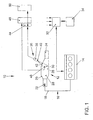
- FIG. 1 1 shows a device, generally designated 10, for measuring the temperature of a catalytic converter 12 through which an exhaust gas of an internal combustion engine flows or flows.
- the device 10 is part of a dynamic engine test bench for internal combustion engines 14, not shown in detail.
- the catalytic converter 12 is located in an exhaust gas line 16 of the internal combustion engine 14 arranged and acted upon by the exhaust gas 18.
- the catalytic converter 12 comprises a housing 20 with an inlet connection 22 for the untreated exhaust gas 18 and an outlet connection 24 for the catalytically treated exhaust gas 18.
- the catalyst support 26 is arranged, which is coated with a catalytically active coating (the so-called washcoat) is.
- a catalytically active coating (the so-called washcoat) is.
- it is a metal catalyst carrier, which is typically designed as a wound catalyst.
- a metal foil carrying the catalytically active coating is provided as a catalyst winding and fitted gas-tight into the housing 20.
- metal catalyst support and ceramic support so-called monoliths or the like can be used.
- the catalyst support 26 has a first end face 28, via which the exhaust gas 18 flows into the catalyst support 26, and a second end face 30, via which the catalytically treated exhaust gas 18 flows.
- the internal combustion engine 14 is associated with an engine controller 32, by means of which the working mode of the internal combustion engine 14 influencing operating parameters, such as ignition angle, throttle position, injection timing, fuel quantities to be injected, valve timing or the like, can be specified. These parameters are usually dependent on a current operating point, such as engine load or Motor speed specified, with stored maps are used. Furthermore, the engine controller 32 may also include control algorithms that cause coordination of the maps as well as the control of certain processes. The engine controller 32 cooperates with a transmission control unit 34, so that the engine controller 32 and the operating parameters of a - FIG. 1 not shown - transmission of the internal combustion engine 14 are known. Other operating parameters, such as signals from gas sensors of the exhaust system, are also included in the engine controller 32nd
- the device 10 further comprises an image recording device 36, which is preferably designed as a near-infrared thermographic camera 38.
- An objective 40 is directed onto the end face 30 of the catalyst winding 26 via an optical window 42, for example made of sapphire glass.
- the end face 30 or at least part of the end face 30 thus forms a measuring surface for measuring the temperature by means of the image recording device 36, as will be explained in more detail below.
- the device 10 comprises only one image recording device 36 which is associated with the end face 30.
- a further image recording device 36 may be provided which is associated with the end face 28.
- the measuring surface may also be formed by an arbitrarily placed sectional surface of the catalyst carrier 26.
- a catalyst can be prepared with an obliquely cut measuring surface or cut into a plurality of carrier blocks, so that there are measuring surfaces between two carrier blocks and thus temperatures at different depths of the catalyst carrier 26 can be determined.
- the image recording device 36 is connected to an evaluation device 44.
- the evaluation device 44 is associated with a calibration 46 which is connected to at least one temperature sensor (thermocouple) 48, which is introduced in a range of O to 2 mm from the end face 30 (and / or end face 28) in the axial direction in the catalyst winding 26 ,
- the thermocouple 48 is inserted into the cells or channels of the carrier 26 and the cell exit, for example, closed with ceramic adhesive to prevent flow through the cells with exhaust gas.
- the evaluation device 44 and the calibration 46 are connected to a storage means 50.
- FIG. 2 shows the arrangement of a catalyst 12 within the device 10 according to a further embodiment in longitudinal section, wherein the same parts as in FIG. 1 provided with the same reference numerals and are not explained again.
- the two catalyst carriers 26 arranged inside the housing 20 are assigned two image recording devices 36 designed as near-infrared thermographic cameras 38.
- Two optical (IR-transparent) windows 42 are provided in the housing 20 of the catalytic converter 12, by means of which a thermographic observation of the end surfaces 28 and 30 is possible.
- the optical window 42 consist for example of a Sapphire crystal or other IR-transparent material.
- the thermocouples (temperature sensors) 48 which are connected to the calibration 46 via signal lines 54 indicated here, are integrated in the end face 28 in the area of the measuring surface 52.
- the thermocouples 48 serve to calibrate the thermographic cameras 38 and for comparison purposes.
- the in the FIGS. 1 and 2 illustrated device 10 has the following function:
- the internal combustion engine 14 is driven in predetermined dynamic test cycles.
- a control of the internal combustion engine 14 via the engine controller 32 wherein operating parameters of the internal combustion engine 14 are set, which were obtained from test drives of a motor vehicle with a corresponding internal combustion engine 14 used on the test bench.
- the exhaust gas line 16 is acted upon by the exhaust gas 18, which has a temperature and pollutant composition dependent on the set operating parameters of the internal combustion engine 14.
- the exhaust gas 18 strikes the end face 28 of the catalyst support 26, flows through the catalyst support 26 and exits again on the end face 30.
- the measuring surface 52 of the end faces 28, 30 is scanned and recorded an image sequence.
- individual images are recorded with the appropriate repetition frequency, which together result in the image sequence.
- the corresponding digital signals supplied by the camera 38 are supplied to the evaluation device 44.
- the intensity of the thermal radiation of the catalyst carrier 26 in the region of the measuring surface is assigned a corresponding solid-state temperature. In this way, maximum temperature loads and real temporal temperature changes (transients) can be determined.
- the actual solid-state temperatures of the catalyst carrier 26 are determined for the engine operating points that have been started and stored as a function of the operating point.
- the temperature measurement is preferably synchronized with the current operating point by triggering.
- a 5V trigger signal output from the test stand is used to trigger the temperature detection.
- the assignment of the measured catalyst temperatures to the operating parameters is stored for each operating situation started on the engine test bench.
- the determined operating parameters are stored depending on the operating point in maps or characteristic curves, which are adjusted in accordance with limits not to be exceeded for the absolute catalyst temperature and for critical positive and negative temperature transients so that in a similar operating situation measured on the test bench increased thermal load does not occur.
- This adapted and stored in the engine control maps is accessed in real vehicle operation to adjust the required operating parameters depending on a requested by a driver by accelerator torque. If, for example, critical temperature loads of the carrier 26 occur on the engine test bench during ignition angle reductions during switching operations of an automatic transmission, the maps and / or control algorithms used for controlling the automatic switching operations are adapted such that the thermal load in the actual vehicle operation is reduced or avoided.
- the calibration of the signals output by the camera 38 that is, the assignment of the measured intensity to actual solid body temperatures is based on stationary engine operating points of the internal combustion engine 14.
- the internal combustion engine 14 is driven at a defined operating point until the catalyst 12 sets an equilibrium temperature. This temperature is over the Temperature sensors 48 measured and communicated to the calibration 46.
- the image sequences of the measuring surface 52 are recorded by means of the camera 38 during this calibration phase, so that an exact assignment to a defined temperature on the surface 28 can take place in accordance with the recorded intensity.
- the assignment of the temperature to the measured intensity is stored in a characteristic curve in the memory 50.
- This calibration of the camera 38 can take place in fixed cycles, for example, before a measurement cycle and / or after a measurement cycle. As a result, the optical measurement by means of the camera 38 influencing disturbing factors, such as contamination (sooting) of the optical window 42 are eliminated.
- the near infrared range is particularly suitable, while for the investigation in the low temperature range (cold start effects) the middle infrared range (MIR) is more sensitive.
- averaging of the measured values can take place.
- Corresponding to the repetition frequency of the camera 38 results in a number of measured values per second.
- an averaging for example from a measurement frequency of 50 Hz to a frequency of 10 Hz, an average value is formed for the selected number of measurements.
- the system according to the invention also allows a very good spatial resolution over the entire measuring surface by recording a two-dimensional intensity profile. As a result, local temperature peaks occurring as a result of inhomogeneous flow of the catalyst through the exhaust gas can be detected and suppressed.
- FIGS. 3 to 15 show the curves of various parameters and operating parameters of the internal combustion engine 14 in various struck on the transient test bench operating situations.
- the temperature of the inlet end surface 28 of the catalyst support 26 was determined thermographically with the thermographic camera 38 and for comparison with a conventional temperature sensor 48, which was located in the immediate vicinity of the thermographically evaluated area.
- the exhaust gas temperature was arranged by means of a temperature sensor arranged upstream of the catalytic converter 12 (in FIG. 1 and 2 not shown).
- the concentration of unburned hydrocarbons HC was determined by the fast FID measurement technique (flame ionization detection).
- a gas sensor also not shown, was arranged upstream of the catalytic converter 12.
- the same reference numerals are used for the same measurands.
- FIG. 3 shows results obtained with multiple ignition misfires at full load operation of the engine 14.
- the ignition of a cylinder was exposed at periodic intervals over a period of about 1 s.
- Curve 60 shows the course of the temperature of catalyst support 26 determined by means of thermography, measured in the middle region of catalyst end face 28.
- Curve 62 shows the temperature profile measured with temperature sensor 48 in the middle of end face 28.
- Curve 64 shows the exhaust gas temperature upstream of catalytic converter 12 and curve 66 shows the curve of the HC concentration upstream of the catalytic converter 12.
- the unburned hydrocarbons are catalytically converted in the catalyst 12, whereby temporary exothermic afterburning causes temperature peaks thermographically observed (curve 60).
- the catalyst temperature starting from a base level at about 870 ° C., rises in each case to over 1000 ° C. in the short term. The half-widths of these temperature peaks are in the range of about 400 to 500 ms.
- periodic cooling of the exhaust gas occurs (curve 64). It is noticeable that no temperature increase is detected by the conventional temperature measurement on the catalyst end face 28 with the thermocouple 48 (curve 62). Rather, after each misfire even a slight cooling is determined, which is caused by the cooler exhaust gas (curve 64).
- thermocouples are unable to detect short-term temperature events that do not result in heating of the thermocouple.
- FIG. 4 shows a similar series of measurements as FIG. 3 , but in each case at intervals of about 2 s, only a single misfire of a cylinder was caused, which corresponds to an event occurring at 50 Hz. The individual misfires lead to an increase in the HC concentration from 700 ppm to about 2000 ppm.
- a temperature increase of the end face 28 from 870 to more than 890 ° C is thermographically registered (curve 60). These temperature peaks, which have a half-width of less than 100 ms, are not registered by the thermocouple arranged on the catalyst end face (curve 62).
- FIGS. 3 and 4 make it clear that both multiple and single sparking misfires lead to a critical short-term increase in the temperature of the catalyst carrier 26. If such misfires occur in full load operation at anyway very high catalyst temperatures, there is a risk of the catalyst becoming heated above the permissible maximum temperature. However, at least just as damaging is the thermal cycling that occurs here with very high heating and cooling rates, whereby the (negative) cooling rate is to be regarded as much more critical than the (positive) heating rate. While hitherto short-term dynamic misfires have been underestimated due to the inadequate detection of the true catalyst temperature in terms of their damage potential, the present invention provides to adjust the engine control so that misfires are more effectively suppressed in full load operation.
- the air was injected between about 8 and 9 s and between 18 and 19 s.
- the exhaust gas is diluted in front of the catalyst by the air injection and the HC concentration thus decreases, there is a short-term increase in temperature of the catalyst by about 70 K.
- the temperature increase is due to the exothermic afterburning of the excess in the rich exhaust gas hydrocarbons with the blown Attributed oxygen.
- the half width of the thermographically determined temperature peaks of about 500 to 700 ms is sufficient to be registered by the thermocouple.
- the absolute temperature change is indicated by about 75% too low and with a certain delay.
- FIG. 6 shows measurement results obtained with a one-time retardation of ignition timing (retardation) by 6 ° CA with otherwise constant operating parameters in partial load engine operation.
- FIGS. 7 to 9 show dynamometer results of dynamic driving cycles.
- the operating parameters necessary for controlling the driving cycles were determined in the transient operation of a vehicle with automatic shifting in the inner track cycle.
- the figures show the influence of Zündwinkellessness notion for the purpose of torque reduction in automatic switching operation. Shown is the temperature of the catalyst detected thermographically at a measuring frequency of 5 Hz (curve 60), the catalyst temperature also measured at the end face with a thermosensor (curve 62) and the HC concentration present upstream of the catalyst (curve 66, only in FIG FIG. 8 ).
- FIG. 9 also shows the temporal catalyst temperature changes (temperature transients) determined by thermography (curve 60 ') as well as thermocouple (curve 62').
- the curves 60 'and 62' were formed by forming the first derivative of the curves 60 and 62, respectively Figure 8 and averaged to 1 Hz for better comparability and smoothing.
- the gear shift to the next higher gear is accompanied by a retraction of the ignition timing in order to achieve the fastest possible and precise reduction of the torque at the gear change due to the deterioration of the engine efficiency.
- a retardation of the ignition angle to a maximum of 3.75 ° kW after ZOT took place.
- FIG. 7 at about 638.5 s and in the FIGS. 8 and 9 at about 97 s ago.
- FIGS. 10 to 12 show results obtained on the test bench in dynamic driving cycles, determined on a high-speed train with a vehicle with manual transmission.
- FIG. 10 are shown thermographically determined with a measuring frequency of 50 Hz Catalyst temperature (curve 60), the thermocouple determined catalyst temperature (curve 62), the exhaust gas HC concentration (curve 66), the speed (curve 70) and the throttle opening (curve 74).
- time interval three switching operations, namely at 115 seconds, 125 and 141.
- a torque reduction takes place during the switching process by the driver himself by this briefly retracting the accelerator pedal.
- the throttle closes (curve 74).
- FIG. 11 that made the FIG. 10 obtained temperature transient - formed from the first derivatives of the curves 60 and 62 - shows heating rates in the course of the three switching operations of over +8000 K / min and cooling rates of about -7000 K / min. Both curves were averaged to 1 Hz for better comparability.
- FIG. 12 shows thermographic and thermocouple temperature transients of the same series of measurements.
- thermographically determined catalyst temperature (curve 60 ) averaged over 10 Hz is shown here in addition to the curves averaged at 1 Hz, and it is clear that the averaging to 10 Hz with respect to the 1 Hz averaging although with A worse signal-to-noise ratio, however, is also associated with a loss of information at 1 Hz, and in particular the true intensities are greatly smoothed.
- FIG. 13 shows a measurement in the dynamic drive cycle at a transition from full load to overrun.
- curve 78 shows the thermographically recorded temperature values at the hottest point of the end face 28, which always lie above those of the center.
- curve 78 shows the advantage of the spatially resolved temperature detection, which allows a consideration of the total catalyst area.
- the purpose of the dashpot function which is usually used to reduce the fuel supply in overrun mode, is to discharge a wall film of the cylinders formed by unburned fuel in such a way that it can still be burnt.
- the wall film demolition is modulated and so much fuel supplied that a mixture that is just ignitable is formed.
- the dashpot function is intended to prevent the unburned ejected fuel wall film burns on the catalyst and thus leads to an increased temperature load. As at the curve 66 of FIG. 12 can be seen, but this succeeds only incomplete. There is a certain output of unburned hydrocarbons HC and their post-combustion at the catalyst, causing there exothermic temperature peaks.
- Curve 78 which shows the thermographically determined catalyst temperature at the hottest point of the end face, shows that catalyst temperatures of up to 980 ° C occur in this case. According to the invention here is the opportunity to optimize the dashpot function so that these temperature peaks are avoided on the catalyst.
- FIGS. 14 and 15 show the influence of a lambda reduction (lambda enrichment) in the dynamic driving cycle in a transition from thrust to full load operation.
- the fuel cut is canceled and set a predetermined air-fuel mixture lambda.
- curve 68 comes in FIG. 14 from the positive infinite and adjusts itself to the given value. Due to the onset of combustion, there is a very rapid heating of the catalyst, as can be seen in the course of the thermographically determined temperature curve 60. Due to inertia, the temperature profile determined with the thermocouple follows the true temperature (curve 62). In order to protect the catalyst from excessive thermal stress in such situations, it is common to lower the combustion lambda more than necessary.
- FIG. 15 shows from the curves 60 and 62 of FIG. 14 determined temperature transients. Both curves were averaged to 1 Hz.
- the temperature detection according to the invention of catalysts with high time resolution and high spatial resolution allows a more accurate conception of the exact temperature behavior in certain operating situations.
Landscapes
- Engineering & Computer Science (AREA)
- Chemical & Material Sciences (AREA)
- Combustion & Propulsion (AREA)
- Mechanical Engineering (AREA)
- General Engineering & Computer Science (AREA)
- Chemical Kinetics & Catalysis (AREA)
- Physics & Mathematics (AREA)
- General Physics & Mathematics (AREA)
- Exhaust Gas After Treatment (AREA)
Description
Die Erfindung betrifft ein Verfahren zur applikativen Anpassung einer Motorsteuerung einer Brennkraftmaschine hinsichtlich der thermischen Belastung eines der Brennkraftmaschine nachgeschalteten Abgaskatalysators nach dem Oberbegriff des Anspruchs 1. Die Erfindung betrifft ferner eine nach dem Verfahren erhaltene Motorsteuerung nach Anspruch 18.The invention relates to a method for applicative adaptation of an engine control of an internal combustion engine with regard to the thermal load of an internal combustion engine downstream catalytic converter according to the preamble of
Üblicherweise werden Brennkraftmaschinen in einem realen Fahrzeugbetrieb mittels Motorsteuergeräten gesteuert. Dabei werden in Abhängigkeit einer von dem Fahrer per Gaspedal angeforderten Leistung sowie einer aktuellen Motordrehzahl die erforderlichen Betriebsparameter vorgegeben. Hierzu gehören beispielsweise Drosselklappenstellung, zugeführte Kraftstoffmasse, Zündwinkel, Ventilsteuerzeiten, Luft-Kraftstoff-Gemisch etc. Diese Parameter werden Kennfeldern entnommen, die abgespeichert in der Motorsteuerung vorliegen. Dabei sind für unterschiedliche Betriebssituationen, beispielsweise Motorkaltstart oder Übergänge aus dem Volllast- in den Schubbetrieb, unterschiedliche Kennfelder vorhanden. Die Koordination der verschiedenen Kennfelder erfolgt ebenfalls durch die Motorsteuerung mittels dort abgespeicherter Algorithmen. Eine weitere Aufgabe der Motorsteuerung besteht in der Einhaltung vorgegebener Grenzwerte, beispielsweise hinsichtlich Laufruhe, Klopfgrenze und Abgasemissionen. Durch diese Rahmenbedingungen wird der Motorbetrieb begrenzt.Usually, internal combustion engines are controlled in a real vehicle operation by means of engine control units. In this case, the required operating parameters are specified as a function of a requested by the driver by accelerator pedal power and a current engine speed. These include throttle position, supplied fuel mass, ignition angle, valve timing, air-fuel mixture, etc. These parameters are taken from maps that are stored in the engine control. In this case, different maps are available for different operating situations, such as engine cold start or transitions from the full load to the overrun. The coordination of the various maps is also done by the engine control means stored there algorithms. Another task of the engine control is to comply with predetermined limits, for example, with regard to smoothness, knock limit and exhaust emissions. These conditions limit engine operation.
Einen weiteren begrenzenden Faktor stellt die thermische Belastbarkeit von im Abgasstrang der Brennkraftmaschine angeordneten Bauteilen, wie Abgaskrümmer, Abgaskatalysatoren und Sonden, dar. Katalysatoren, die aus einem vom Abgas durchströmbaren Träger aus Metall oder Keramik sowie aus einer auf dem Träger vorhandenen katalytischen Beschichtung, dem so genannten Washcoat, aufgebaut sind, sind extremen thermischen Einflüssen ausgesetzt. Diese werden zum einen durch die hohen Verbrennungsprozessbedingten Abgastemperaturen verursacht, die besonders motornah angeordnete Katalysatoren betreffen. Des Weiteren führt die exotherme Umsetzung der verschiedenen Abgaskomponenten, insbesondere der unverbrannten Kohlenwasserstoffe HC, zu sehr hohen Wärmefreisetzungen im Katalysator selbst. Infolge ungleichmäßiger Anströmung durch das Abgas sowie der radial ungleichmäßig verlaufenden Reaktionsfront innerhalb des Katalysators kommt es zusätzlich zu lokal ungleichmäßigen Aufheizungen des Katalysators. Neben den kritischen Absoluttemperaturen und den örtlichen Temperaturgradienten führt der dynamische Fahrzeugbetrieb ferner zu einer hohen thermischen Wechselbelastung mit extremen Aufheiz- und Abkühlraten. All diese Faktoren können Schädigungen der Trägermaterialien, beispielsweise in Form von Zellausbrüchen, bis hin zum sofortigen Materialversagen verursachen. Auch Abplatzungen des Washcoats werden beobachtet. Darüber hinaus führt die thermische Alterung des Washcoats über die Katalysatorlaufzeit zu einer Verschlechterung der Konvertierungsrate, so dass Emissionsgrenzwerte nicht mehr eingehalten werden können.Another limiting factor is the thermal load capacity of arranged in the exhaust system of the internal combustion engine components, such as exhaust manifold, catalytic converters and probes., Catalysts, which can be traversed by an exhaust gas from the carrier metal or ceramic and from an existing on the support catalytic coating, the so Washcoat, are exposed to extreme thermal influences. These are caused on the one hand by the high combustion process-related exhaust gas temperatures, which relate particularly close to the engine arranged catalysts. Furthermore, the exothermic implementation of the various exhaust gas components, in particular the unburned hydrocarbons HC, leads to very high heat releases in the catalyst itself. As a result of uneven flow through the exhaust gas and the radially uneven reaction front within the Catalyst occurs in addition to locally uneven heating of the catalyst. In addition to the critical absolute temperatures and the local temperature gradients, the dynamic vehicle operation also leads to a high thermal cycling load with extreme heating and cooling rates. All of these factors can cause damage to the substrates, such as cell outbreaks, to immediate material failure. Spalling of the washcoat is also observed. In addition, the thermal aging of the washcoat over the catalyst life leads to a deterioration in the conversion rate, so that emission limits can no longer be met.
Um das Temperaturverhalten von Katalysatoren zu ermitteln, ist bekannt, im stationären oder instationären Betrieb, das heißt auf Fahrzeugteststrecken beziehungsweise auf Fahrzeugprüfständen, die Brennkraftmaschine in vorgegebenen Fahrzyklen zu betreiben und die Temperatur des Katalysators zu messen. Die relevanten Betriebsparameter der Brennkraftmaschine sowie die ermittelten Katalysatortemperaturen werden dann abgespeichert. Anschließend werden dann Funktionalitäten der Motorsteuerung, das heißt Kennfelder sowie Steueralgorithmen, derart adaptiert, dass im realen Fahrzeugbetrieb, wenn die Brennkraftmaschine durch die Motorsteuerung gesteuert wird, in einer entsprechenden Betriebssituation die erhöhte thermische Belastung des Katalysators vermieden wird. Es wird insbesondere angestrebt eine kritische Maximaltemperatur nicht zu überschreiten, wobei es üblich ist, einen gewissen Sicherheitsabstand zur kritischen Maximaltemperatur einzuhalten.In order to determine the temperature behavior of catalysts, it is known to operate in stationary or transient operation, that is, on vehicle test tracks or on vehicle test stands, the internal combustion engine in predetermined driving cycles and to measure the temperature of the catalyst. The relevant operating parameters of the internal combustion engine and the determined catalyst temperatures are then stored. Subsequently, functionalities of the engine control, ie maps and control algorithms are then adapted such that in real vehicle operation, when the internal combustion engine is controlled by the engine control, in a corresponding operating situation, the increased thermal load of the catalyst is avoided. It is particularly desirable not to exceed a critical maximum temperature, whereby it is customary to maintain a certain safety distance to the critical maximum temperature.
Bekannte Methoden zur Messung der Katalysatortemperatur verwenden Temperatursensoren (Thermoelemente), die beispielsweise an einer Eintrittsstirnfläche und/oder Austrittsstirnfläche des Katalysators angeordnet werden (
Darüber hinaus ist die berührungslose Temperaturmessung mittels schneller HC-Messtechnik bekannt. Hierbei wird stromauf des Katalysators die HC-Konzentration durch einen Flammenionisationsdetektor (FID) ermittelt. Aus der Kenntnis der HC-Konzentration sowie des Abgasmassenstroms wird dann die exotherme Erwärmung des Katalysators infolge des chemischen Energieeintrags berechnet. Problematisch hieran ist jedoch einerseits, dass Abgastemperatureinflüsse nicht berücksichtigt werden. Darüber hinaus lassen sich mit der schnellen HC-Messung einige exotherme Vorgänge bestimmter Betriebssituationen nicht detektieren.In addition, non-contact temperature measurement by means of fast HC measurement technology is known. In this case, the HC concentration is determined by a flame ionization detector (FID) upstream of the catalyst. From the knowledge of the HC concentration and the exhaust gas mass flow then the exothermic heating of the catalyst is calculated as a result of the chemical energy input. The problem here, however, on the one hand, that exhaust gas temperature influences are not taken into account. In addition, with the rapid HC measurement, some exothermic processes of certain operating situations can not be detected.
Es sind ferner thermographische Verfahren zur berührungslosen Messung von Oberflächentemperaturen aus anderen Technikbereichen, beispielsweise zur Materialprüfung oder Überwachung mechanisch belasteter Bauteile, bekannt. Dabei wird mit einer Infrarotkamera die von dem Werkstück emittierte Infrarotstrahlung erfasst und mit einem Referenzstrahler bekannter Temperatur abgeglichen (
Aufgabe der vorliegenden Erfindung ist, ein Verfahren zur Anpassung einer Motorsteuerung zu schaffen, das eine genauere Einhaltung zulässiger Temperaturbereiche von Abgaskatalysatoren gewährleistet, um eine thermische Alterung des Katalysators zu vermindern. Es soll ferner eine entsprechend erhaltene Motorsteuerung bereitgestellt werden.The object of the present invention is to provide a method for adjusting an engine control, which ensures a more accurate compliance with permissible temperature ranges of catalytic converters in order to reduce thermal aging of the catalyst. It is also intended to provide a correspondingly obtained motor control.
Diese Aufgabe wird durch ein Verfahren mit den Merkmalen des Anspruchs 1 gelöst. Erfindungsgemäß ist vorgesehen, dass die Katalysatortemperatur bei einem Temperatursprung (ΔT) in einem Bereich von 20 K bis 150 K bei einer Ausgangstemperatur in einem Bereich von 500 °C bis 950 °C mit mindestens einer der folgenden Zeitauflösungen mittels Thermographie ermittelt wird:
- nach 10 ms wird mindestens 10%, insbesondere mindestens 15 % des Temperatursprungs erfasst,
- nach 100ms wird mindestens 20%, insbesondere mindestens 30% des Temperatursprungs erfasst,
- nach 500 ms wird mindestens 35 %, insbesondere mindestens 50 % des Temperatursprungs erfasst,
- nach 1000 ms wird mindestens 50 %, insbesondere mindestens 70 % des Temperatursprungs erfasst.
- after 10 ms at least 10%, in particular at least 15% of the temperature jump is recorded,
- after 100ms at least 20%, in particular at least 30% of the temperature jump is detected,
- after 500 ms at least 35%, in particular at least 50% of the temperature jump is recorded,
- after 1000 ms at least 50%, in particular at least 70% of the temperature jump is detected.
Die erfindungsgemäßen hohen Zeitauflösungen, mit denen die Katalysatortemperatur im stationären und/oder instationären Testbetrieb erfasst werden, sind so abgestimmt, dass auch sehr schnelle und sehr kurz anhaltende Temperaturereignisse, insbesondere Temperaturspitzen im Katalysator, detektiert werden. Das Vorliegen derartig schneller und kurzfristiger Temperaturänderungen am Katalysator wurde im Rahmen der vorliegenden Erfindung erstmalig und überraschend erkannt. Die erfindungsgemäß ermöglichte Detektion solcher Temperaturereignisse gestattet eine sehr genaue Anpassung der Motorsteuerung, insbesondere der in der Motorsteuerung gespeicherten Kennfelder und Steueralgorithmen hinsichtlich der tatsächlichen thermischen Belastung des Katalysators. Durch die erfindungsgemäßen Maßnahmen ist es nunmehr möglich, den Katalysator vor thermischen Belastungen zu schützen, deren Existenz bislang unbekannt war und nur anhand der visuell zu beobachtenden Katalysatorschäden nachträglich vermutet werden konnte. Typische Betriebssituationen, bei denen unter Anwendung der erfindungsgemäßen Messtechnik entsprechend schnelle Temperaturcharakteristiken gefunden wurden, sind beispielsweise Zündaussetzer, verspätete Lambdaabsenkung zum Bauteilschutz (Bauteilschutzanfettung) und Schaltvorgänge. Infolgedessen kann die thermische Alterung von Katalysatoren nunmehr wirkungsvoll verzögert werden und eine hohe Abgassicherheit gewährleistet werden. Die Kenntnis der tatsächlichen, von der Abgastemperatur unverfälschten Bauteiltemperatur erlaubt darüber hinaus die Vorgabe von Schwellenwerten für die thermische Grenzbelastung des Katalysatorträgers und/oder des Washcoats mit einem geringeren Sicherheitsabstand, da Temperaturüberschwinger sicher detektiert und durch geeignete applikative Maßnahmen reduziert werden können. Im Rahmen der vorliegenden Erfindung werden unter dem Begriff applikative Maßnahme beziehungsweise Motorapplikation die Ermittlung aller in einem Motorsteuerungsgerät gespeicherten motorspezifischen Funktionalitäten verstanden, dies sind insbesondere Kennfelder, die eine Zuordnung betriebsrelevanter Parameter zu entsprechenden Betriebspunkten enthalten sowie Steueralgorithmen, die beispielsweise eine Verknüpfung der Kennfelder bewirken. Bei überlagernden Applikationsereignissen, insbesondere im hochdynamischen Fahrzeugbetrieb (beispielsweise Volllast-Schubwechsel), kann der Einfluss einzelner Betriebsparameter wie Zündwinkel, Drosselklappenstellung oder Lambda, hinsichtlich der erlaubten Temperaturbelastung des Katalysators gezielt angepasst werden.The high time resolutions according to the invention, with which the catalyst temperature is detected in stationary and / or transient test mode, are tuned so that even very fast and very short-lasting temperature events, in particular temperature peaks in the catalyst, are detected. The presence of such rapid and short-term temperature changes to the catalyst was recognized for the first time and surprisingly in the context of the present invention. The inventively enabled detection of such temperature events allows a very accurate adaptation of the engine control, in particular the maps stored in the engine control and control algorithms with respect to the actual thermal stress of the catalyst. The inventive measures it is now possible to protect the catalyst from thermal stresses whose existence was previously unknown and could be suspected only based on the visually observed catalyst damage. Typical operating situations in which correspondingly fast temperature characteristics have been found using the measuring technique according to the invention include, for example, misfiring, delayed lambda reduction for component protection (component protection) and switching operations. As a result, the thermal aging of catalysts can now be effectively delayed and high exhaust gas safety can be ensured. Knowing the actual component temperature, which is unadulterated by the exhaust gas temperature, moreover makes it possible to specify threshold values for the thermal limit load of the catalyst support and / or the washcoat with a smaller safety margin, since temperature overshoots can be reliably detected and reduced by suitable application measures. In the context of the present invention, the term applicative measure or motor application means the determination of all engine-specific functionalities stored in an engine control unit; these are, in particular, maps which contain an assignment of operation-relevant parameters to corresponding operating points and control algorithms which, for example, link the maps. In the case of overlapping application events, in particular in highly dynamic vehicle operation (for example full-load thrust change), the influence of individual operating parameters such as ignition angle, throttle valve position or lambda can be adapted specifically with regard to the permitted temperature load on the catalytic converter.
Nach einer vorteilhaften Ausgestaltung der Erfindung ist weiterhin vorgesehen, zeitliche Temperaturveränderungen (Temperaturtransienten) im Katalysator mit Aufheizraten und/oder Abkühlraten von mindestens 100 K/s, insbesondere mindestens 200 K/s, vorzugsweise von mindestens 1000 K/s, mit der erfindungsgemäßen Zeitauflösung zu erfassen. Derartige Prozesse können mit Temperatursensoren nur mit einer erheblichen Verzögerung erfasst werden.According to an advantageous embodiment of the invention is further provided, temporal temperature changes (temperature transients) in the catalyst with heating rates and / or cooling rates of at least 100 K / s, in particular at least 200 K / s, preferably at least 1000 K / s, with the time resolution according to the invention to capture. Such processes can be detected with temperature sensors only with a considerable delay.
Im Falle von kurzfristig auftretender Temperaturspitzen der Katalysatortemperatur (Temperaturüberschwinger) ist bevorzugt vorgesehen, die maximale Zeitauflösung der Temperaturmessung so auszulegen, dass Temperaturspitzen mit Halbwertsbreiten von höchstens 1000 ms, insbesondere höchstens 500 ms, erfasst werden, wobei mindestens 50 % des absoluten Temperatursprungs erfasst werden. Es ist besonders vorteilhaft vorgesehen, Halbwertsbreiten von höchstens 250 ms aufzulösen.In the case of short-term temperature peaks of the catalyst temperature (temperature overshoot) is preferably provided to interpret the maximum time resolution of the temperature measurement so that temperature peaks with half-widths of at most 1000 ms, in particular at most 500 ms, are detected, wherein at least 50% of the absolute temperature jump are detected. It is particularly advantageous to resolve half-value widths of at most 250 ms.
Die erfindungsgemäßen hohen Zeitauflösungen werden erreicht, wenn die Katalysatortemperatur mit einer Messfrequenz von mindestens 1 Hz, insbesondere von mindestens 10 Hz, erfasst wird. Bevorzugt sind jedoch Messfrequenzen von 50 HZ oder höher, wobei sogar Frequenzen von über 100 Hz bis in den kHz-Bereich möglich sind. Auf diese Weise können Temperaturimpulse bis in den ms-Bereich aufgelöst werden. Damit nicht zu kurzfristige Temperaturschwankungen erfasst werden, die aufgrund des verzögerten Wärmeübergangs durch die Beschichtung keinen Einfluss auf die tatsächliche Bauteiltemperatur des Trägers haben, kann vorteilhaft vorgesehen sein, bei einer Messfrequenz größer als 10 Hz die erfassten Messwerte zu mitteln, beispielsweise auf 10 Hz. Hierdurch wird zudem das Signal-Rausch-Verhältnis verbessert.The high time resolutions according to the invention are achieved when the catalyst temperature is detected at a measurement frequency of at least 1 Hz, in particular of at least 10 Hz. However, measurement frequencies of 50 Hz or higher are preferred, even frequencies of more than 100 Hz up to the kHz range being possible. In this way, temperature pulses can be resolved down to the ms range. In order not to detect short-term temperature fluctuations, which due to the delayed heat transfer through the coating have no influence on the actual component temperature of the carrier, it may be advantageous to average the detected measured values, for example to 10 Hz, at a measuring frequency greater than 10 Hz In addition, the signal-to-noise ratio is improved.
Während die vorausgehend genannten Maßnahmen die Zeitauflösung der Temperaturmessung betreffen, kann eine genauere Berücksichtigung der thermischen Belastung von Katalysatoren auch durch einen weiteren Aspekt den jedoch nicht Teil der vorliegenden Erfindung ist, erreicht werden, indem nämlich die thermische Belastung des Katalysators ortsaufgelöst erfasst wird. Insbesondere ist vorgesehen, dass die thermische Belastung über eine Messfläche des Katalysators von mindestens 4 cm2, insbesondere mindestens 6,5 cm2, und vorzugsweise von mindestens 9 cm2 ermittelt wird, wobei die thermische Belastung innerhalb diese Messfläche an mindestens 2 Messpunkten, insbesondere an mindestens 5, und vorzugsweise an mindestens 20 Messpunkten, bestimmt wird. Es hat sich nämlich herausgestellt, dass infolge inhomogener Anströmung des Katalysators durch das Abgas eine lokal ungleichmäßige Temperaturverteilung erfolgt. Zusätzlich sorgt beispielsweise die Struktur des Katalysatorträgers für ein ungleichmäßiges Aufheiz- und Abkühlverhalten. Insbesondere entstehen im Fall von Metallträgern infolge einer speziellen Wickeltechnik, mit denen sie hergestellt werden, Stellen, an denen zwei glatte Folien aneinander liegen und eine erhöhte thermische Trägheit zu beobachten ist. Diese Stellen zeichnen sich sowohl bei Erwärmungs- als auch bei Abkühlungsprozessen des Katalysators durch einen nachhinkenden Temperaturverlauf aus. Die hierbei entstehenden Materialspannungen können mechanische Schädigungen des Katalysators zur Folge haben. Erfolgt eine ortsaufgelöste Temperaturerfassung, so können auch diese so genannten Hot-Spots im Rahmen der Applikation der Motorsteuerung berücksichtigt und weitgehend unterbunden werden. Dies ist jedoch nicht Teil der verliegenden Erfindung.While the above-mentioned measures relate to the time resolution of the temperature measurement, a more precise consideration of the thermal stress of catalysts can also be achieved by a further aspect, which is not part of the present invention, namely, the location of the thermal stress of the catalyst is detected in a spatially resolved manner. In particular, it is provided that the thermal load over a measuring surface of the catalyst of at least 4 cm 2 , in particular at least 6.5 cm 2 , and preferably of at least 9 cm 2 is determined, the thermal load within this measuring surface at least 2 measuring points, in particular at least 5, and preferably at least 20 measuring points is determined. It has been found that due to inhomogeneous flow of the catalyst through the exhaust gas is a locally non-uniform temperature distribution. In addition, for example, the structure of the catalyst carrier ensures uneven heating and cooling behavior. In particular, in the case of metal supports, as a result of a special winding technique with which they are made, there are points where two smooth films abut one another and increased thermal inertia is observed. These sites are characterized both by heating and cooling processes of the catalyst by a lagging temperature profile. The resulting material stresses can cause mechanical damage to the catalyst. If a spatially resolved temperature detection takes place, these so-called hot spots can also be taken into account and largely prevented in the context of the application of the motor control. However, this is not part of the present invention.
Es ist besonders bevorzugt vorgesehen, sowohl die oben genannten Maßnahmen zur zeitaufgelösten Temperaturerfassung als auch die der ortsaufgelösten Temperaturerfassung miteinander zu kombinieren. Auf diese Weise können sowohl dynamische Temperaturänderungen (Temperaturtransienten) als auch örtliche Temperaturunterschiede im Katalysator (Temperaturgradienten) berücksichtigt werden.It is particularly preferred to combine both the above-mentioned measures for time-resolved temperature detection as well as the spatially resolved temperature detection. In this way, both dynamic temperature changes (temperature transients) and local temperature differences in the catalyst (temperature gradients) can be taken into account.
Eine besonders geeignete Methode, um Katalysatortemperaturen mit hoher Zeit- und Ortauflösung zu erfassen, stellt die Thermographie, insbesondere die Infrarotthermographie dar, wobei in einfacher Weise mittels einer Thermographiekamera eine der tatsächlichen Ist-Temperatur entsprechende elektromagnetische Strahlung (Festkörperstrahlung) gemessen wird, die von dem Katalysator abgestrahlt wird. Entsprechend einer gewählten Messfläche lässt sich so in einfacher Weise auch der Temperaturverlauf über der Fläche ermitteln. Dabei ist für die Detektion für Temperaturen oberhalb von 500 °C der nahe Infrarotbereich besonders geeignet, während für niedrigere Temperaturen zwischen 20 und 500 °C, beispielsweise zur Beobachtung von Kaltstarteffekten, der mittlere Infrarotbereich empfindlicher ist.A particularly suitable method to detect catalyst temperatures with high time and place resolution is the thermography, in particular the infrared thermography, wherein in a simple manner by means of a thermographic camera of the actual actual temperature corresponding electromagnetic radiation (solid state radiation) is measured by the Catalyst is emitted. In accordance with a selected measuring surface, the temperature profile over the surface can thus be determined in a simple manner. In this case, for the detection of temperatures above 500 ° C, the near infrared range is particularly suitable, while for lower temperatures between 20 and 500 ° C, for example, to observe cold start effects, the middle infrared range is more sensitive.
Besonders vorteilhaft erfolgt die Temperaturmessung an einer Eintrittsstirnfläche und/oder einer Austrittsstirnfläche des Katalysators. Im Falle mehrteiliger, beabstandet voreinander angeordneter Träger kommt jedoch auch eine Messung der ausgebildeten Zwischenflächen in Frage.Particularly advantageously, the temperature measurement takes place at an inlet end face and / or an outlet end face of the catalyst. In the case of multi-part, spaced apart arranged carrier but also a measurement of the formed intermediate surfaces in question.
Die erfindungsgemäße Methode zeichnet sich durch die Erfassung der tatsächlichen Festkörpertemperatur aus, wobei auch möglich ist, die Temperatur des Trägers des Katalysators getrennt von der des Washcoats zu ermitteln und zu berücksichtigen.The inventive method is characterized by the detection of the actual solid-state temperature, wherein it is also possible to determine the temperature of the support of the catalyst separately from that of the washcoat and take into account.
Die erfindungsgemäße Erfassung der Katalysatortemperatur im stationären und/oder instationären Betrieb zum Zwecke der Anpassung der Funktionalitäten der Motorsteuerung, das heißt der dort gespeicherten Kennfelder und/oder Steueralgorithmen, wird vorzugsweise für solche Betriebssituationen durchgeführt, in denen ein hohes thermisches Risiko für den Katalysator besteht. Insbesondere kann das Verfahren für Betriebssituationen angewendet werden, die mit einem hohen Risiko für das Auftreten von Einfach- und/oder Mehrfachzündaussetzern emhergehen. Die bei Zündaussetzern auftretenden Temperaturspitzen sind so kurz und haben folglich eine so geringe Halbwertsbreite, dass sie mit herkömmlichen Thermoelementen aufgrund ihrer thermischen Trägheiten nicht detektierbar sind. Weitere Betriebssituationen, die mit hohen und schnellen Temperaturänderungen verbunden sind, sind etwa Zündwinkelverstellungen, insbesondere Spätverstellungen (Zündwinkelrücknahmen); Schaltvorgänge bei Automatik- und bei Handschaltgetrieben oder hochdynamische Vorgänge, insbesondere Übergänge von Volllast- in Schubbetrieb. Weitere applikativ zu adaptierende Betriebssituationen sind etwa Lambdaabsenkungen, ausgehend von fettem Lambda als Maßnahme zum Bauteilschutz; Lufteinblasungen in den Krümmer bei fettem Lambda sowie schnelle Lambdaoszillationen. Dabei werden für jede Betriebssituation die Katalysatortemperaturen zusammen mit den maßgeblichen Betriebsparametern ermittelt. Nachfolgend werden die zur Steuerung der Brennkraftmaschine im realen Fahrzeugbetrieb in einer gleichartigen Betriebssituation verwendeten Kennfelder und Steueralgorithmen werden dann so adaptiert, dass bei ihrer Anwendung die erhöhte thermische Belastung des Katalysators vermieden wird. Insbesondere wird die applikative Maßnahme derart ausgelegt, dass eine katalysatorspezifische kritische Absoluttemperatur des Katalysators und/oder eine kritische Aufheizrate und/oder eine kritische Abkühlrate nicht erreicht wird. Es werden somit nicht nur besonders hohe Katalysatortemperaturen vermieden, sondern auch sehr schnelle Aufheiz- und Abkühlprozesse. Die applikative Maßnahme kann beispielsweise in Form einer Kennfeldanpassung durch Grenzwertfestlegung erfolgen, welche die in einer Betriebssituation wählbaren Betriebsparameter begrenzt. Denkbar ist auch, als applikative Maßnahme eine Anpassung von Steueralgorithmen vorzusehen, die in thermisch kritischen Betriebssituationen eine hinsichtlich der thermischen Belastung des Katalysators geeignete Steuerung der Brennkraftmaschine vornehmen.The detection according to the invention of the catalyst temperature in stationary and / or transient operation for the purpose of adapting the functionalities of the engine control, that is to say the maps and / or control algorithms stored there, is preferably carried out for those operating situations in which there is a high thermal risk for the catalytic converter. In particular, the method can be used for operating situations which proceed with a high risk of the occurrence of single and / or multiple ignition misfires. The temperature peaks occurring at misfires are so short and thus have such a low half-width that they are not detectable with conventional thermocouples due to their thermal inertia. Other operating situations that are associated with high and rapid changes in temperature are about Zündwinkelverstellungen, in particular retards (Zündwinkelrücknahmen); Switching operations in automatic and manual transmissions or highly dynamic processes, in particular transitions from full load to coasting mode. Further operating situations to be adapted by application are, for example, lambda subsidence, starting from rich lambda as a measure for component protection; Injection of air into the manifold at high lambda and fast lambda oscillations. In this case, the catalyst temperatures are determined together with the relevant operating parameters for each operating situation. Subsequently, the maps and control algorithms used to control the internal combustion engine in real vehicle operation in a similar operating situation are then adapted so that the increased thermal load of the catalyst is avoided in their application. In particular, the applicative measure is designed such that a catalyst-specific critical temperature of the absolute temperature of the catalyst and / or a critical heating rate and / or a critical cooling rate is not achieved. Not only are particularly high catalyst temperatures avoided, but also very fast heating and cooling processes. The applicative measure can take place, for example, in the form of a characteristic map adaptation by limiting value definition, which limits the operating parameters that can be selected in an operating situation. It is also conceivable to provide an adaptation of control algorithms as an applicational measure, which, in thermally critical operating situations, make a control of the internal combustion engine suitable with regard to the thermal load of the catalytic converter.
Die Erfindung betrifft ferner ein Verfahren zur Steuerung einer Brennkraftmaschine. Nach dem Verfahren werden Betriebsparameter zur Steuerung der Brennkraftmaschine in Abhängigkeit einer aktuellen Betriebssituation anhand von applikativen Mitteln einer Motorsteuerung, insbesondere anhand von Kennfeldern und/oder Steueralgorithmen, in einer Weise vorgegeben werden, dass eine erhöhte thermische Belastung des Katalysators vermieden wird. Dabei werden die applikativen Mittel in einem stationären und/oder instationären Betrieb der Brennkraftmaschine ermittelt, indem in einer gleichartigen Betriebssituation eine Katalysatortemperatur in Abhängigkeit der vorgegebenen Betriebsparameter erfasst wird. Dabei ist erfindungsgemäß vorgesehen, die Katalysatortemperatur im stationären und/oder instationären Betrieb in der oben beschriebenen Weise, insbesondere mit einer der oben beschriebenen Zeitauflösungen, zu erfassen.The invention further relates to a method for controlling an internal combustion engine. According to the method, operating parameters for controlling the internal combustion engine as a function of a current operating situation are specified in a manner based on application means of a motor control, in particular based on characteristic diagrams and / or control algorithms, such that an increased thermal load on the catalytic converter is avoided. In this case, the applicative means are determined in a stationary and / or transient operation of the internal combustion engine by detecting a catalyst temperature in a similar operating situation as a function of the predetermined operating parameters. It is inventively provided to detect the catalyst temperature in stationary and / or transient operation in the manner described above, in particular with one of the time resolutions described above.
Die Erfindung betrifft ferner eine Motorsteuerung, die applikative Mittel (Funktionalitäten), insbesondere Kennfelder und/oder Steueralgorithmen umfasst, die in der oben beschriebenen Weise erhalten wurden.The invention further relates to a motor control comprising applicative means (functionalities), in particular maps and / or control algorithms, which were obtained in the manner described above.
Weitere bevorzugte Ausgestaltungen der Erfindung ergeben sich aus den übrigen, in den Unteransprüchen genannten Merkmalen.Further preferred embodiments of the invention will become apparent from the remaining, mentioned in the dependent claims characteristics.
Die Erfindung wird nachfolgend in einem Ausführungsbeispiel anhand der zugehörigen Zeichnungen näher erläutert. Es zeigen:
Figur 1- eine schematische Darstellung einer Brennkraftmaschine mit einer erfindungsgemäßen Motorsteuerung;
Figur 2- Anordnung eines Abgaskatalysators mit Thermographiekameras ;
- Figur 3
- zeitliche Verläufe einer mittels Thermographie und Thermoelement ermittelten Katalysatortemperatur, einer mittels Thermoelement ermittelten Abgastemperatur sowie einer HC-Konzentration im Laufe periodischer Mehrfachzündaussetzer bei Volllast ;
Figur 4- zeitliche Verläufe einer mittels Thermographie und Thermoelement ermittelten Katalysatortemperatur sowie einer HC-Konzentration im Laufe periodischer Einfachfachzündaussetzer bei Volllast ;
Figur 5- zeitliche Verläufe der Größen wie in
Figur 3 gemessen im Laufe periodischer Lufteinblasungen im Krümmer bei fettem Abgas; Figur 6- zeitliche Verläufe einer mittels Thermographie und Thermoelement ermittelten Katalysatortemperatur im Laufe einer einmaligen Zündwinkelrücknahme;
- Figur 7 -9
- zeitliche Verläufe verschiedener Messgrößen und Betriebsparameter sowie Temperaturtransienten im Laufe einer kritischen Zündwinkelrücknahme bei Schaltvorgängen eines Automatikgetriebes;
- Figur 10 - 12
- zeitliche Verläufe verschiedener Messgrößen und Betriebsparameter sowie Temperaturtransienten während Schaltvorgängen eines Handschaltgetriebes;
Figur 13- zeitliche Verläufe verschiedener Messgrößen und Betriebsparameter bei einem Volllast-Schub-Übergang; und
Figur - zeitliche Verläufe verschiedener Messgrößen und Betriebsparameter sowie zeitliche Temperaturgradienten bei einem Schub-Volllast-Übergang.
- FIG. 1
- a schematic representation of an internal combustion engine with an engine control according to the invention;
- FIG. 2
- Arrangement of a catalytic converter with thermographic cameras;
- FIG. 3
- chronological courses of a temperature determined by means of thermography and thermocouple catalyst temperature, an exhaust gas temperature determined by means of a thermocouple and an HC concentration in the course of periodic Mehrfachzündaussetzer at full load;
- FIG. 4
- chronological courses of a temperature determined by means of thermography and thermocouple catalyst temperature and an HC concentration in the course of periodic Einfachfachzündaussetzer at full load;
- FIG. 5
- temporal courses of the sizes as in
FIG. 3 Measured in the course of periodic Lufteinblasungen in the manifold with rich exhaust gas; - FIG. 6
- chronological courses of a temperature determined by means of thermography and thermocouple catalyst temperature in the course of a single Zündwinkelrücknahme;
- Figure 7 -9
- chronological courses of different measured quantities and operating parameters as well as temperature transients in the course of a critical ignition angle retraction during switching operations of an automatic transmission;
- FIGS. 10 to 12
- temporal courses of different parameters and operating parameters as well as temperature transients during switching operations of a manual transmission;
- FIG. 13
- temporal courses of different parameters and operating parameters in a full-load thrust transition; and
- FIG. 14, 15
- temporal courses of different measured variables and operating parameters as well as temporal temperature gradients in a thrust-full load transition.
Der Verbrennungskraftmaschine 14 ist eine Motorsteuerung 32 zugeordnet, mittels der den Arbeitsmodus der Verbrennungskraftmaschine 14 beeinflussende Betriebsparameter, wie beispielsweise Zündwinkel, Drosselklappenstellung, Einspritzzeitpunkte, einzuspritzende Kraftstoffmengen, Ventilsteuerzeiten oder dergleichen, vorgebbar sind. Diese Parameter werden üblicherweise in Abhängigkeit von einen aktuellen Betriebspunkt, wie Motorlast oder Motordrehzahl vorgegeben, wobei abgespeicherte Kennfelder verwendet werden. Ferner kann die Motorsteuerung 32 auch Steueralgorithmen enthalten, die eine Koordination der Kennfelder sowie die Steuerung bestimmter Prozesse bewirken. Die Motorsteuerung 32 wirkt mit einem Getriebesteuergerät 34 zusammen, so dass der Motorsteuerung 32 auch die Betriebsparameter eines - in
Die Vorrichtung 10 umfasst ferner eine Bildaufzeichnungseinrichtung 36, die vorzugsweise als Nah-Infrarot-Thermographiekamera 38 ausgebildet ist. Ein Objektiv 40 ist über ein optisches Fenster 42, beispielsweise aus Saphirglas, auf die Stirnfläche 30 der Katalysatorwicklung 26 gerichtet. Die Stirnfläche 30 oder zumindest ein Teil der Stirnfläche 30 bildet somit eine Messfläche zum Messen der Temperatur mittels der Bildaufzeichnungseinrichtung 36, wie nachfolgend noch näher erläutet wird.The
Gemäß der in
Die Bildaufzeichnungseinrichtung 36 ist mit einer Auswerteeinrichtung 44 verbunden. Der Auswerteeinrichtung 44 ist eine Kalibrierung 46 zugeordnet, die mit wenigstens einem Temperatursensor (Thermoelement) 48 verbunden ist, der in einen Bereich von O bis 2 mm von der Stirnfläche 30 (und/oder Stirnfläche 28) in axialer Richtung in die Katalysatorwicklung 26 eingebracht ist. Hierfür wird das Thermoelement 48 in die Zellen beziehungsweise Kanäle des Trägers 26 eingeschoben und der Zellaustritt beispielsweise mit Keramikkleber verschlossen, um eine Durchströmung der Zellen mit Abgas zu verhindern. Die Auswerteeinrichtung 44 und die Kalibrierung 46 sind mit einem Speichermittel 50 verbunden.The
Die in den
Mittels des Motorenprüfstandes wird die Verbrennungskraftmaschine 14 in vorgegebenen dynamischen Testzyklen gefahren. Hierbei erfolgt eine Ansteuerung der Verbrennungskraftmaschine 14 über die Motorsteuerung 32, wobei Betriebsparameter der Verbrennungskraftmaschine 14 eingestellt werden, die aus Testfahrten eines Kraftfahrzeuges mit einer auf dem Prüfstand verwendeten entsprechenden Verbrennungskraftmaschine 14 gewonnen wurden. Entsprechend der Ansteuerung der Verbrennungskraftmaschine 14 erfolgt eine Beaufschlagung des Abgasstranges 16 mit dem Abgas 18, das eine von den eingestellten Betriebsparametern der Verbrennungskraftmaschine 14 abhängige Temperatur und Schadstoffzusammensetzung besitzt. Das Abgas 18 trifft auf die Stirnfläche 28 des Katalysatorträgers 26, durchströmt den Katalysatorträger 26 und tritt auf der Stirnfläche 30 wieder aus.By means of the engine test stand, the
Über die Nah-Infrarot-Thermographiekamera 38 wird die Messfläche 52 der Stirnflächen 28, 30 abgetastet und eine Bildsequenz aufgenommen. Entsprechend der Ansteuerung der Kamera 38, beispielsweise mit einer Taktung ≥ 50 Hz, werden mit entsprechende Wiederholfrequenz Einzelbilder aufgenommen, die zusammen die Bildsequenz ergeben. Hierbei wird jeweils die Intensität der Festkörperstrahlung im Nah-Infrarot-Wellenlängenbereich im Vollbild über die Messfläche 52 aufgezeichnet. Die entsprechenden von der Kamera 38 gelieferten digitalen Signale werden der Auswerteeinrichtung 44 zugeführt. Mittels der Kalibrierung 46 wird der intensität der Wärmestrahlung des Katalysatorträgers 26 im Bereich der Messfläche, eine entsprechende Festkörpertemperatur zugeordnet. Hierdurch lassen sich maximale Temperaturbelastungen und reale zeitliche Temperaturänderungen (Transienten) ermitteln.About the near-
Es werden für die angefahrenen Motorbetriebspunkte somit die tatsächlichen Festkörpertemperaturen des Katalysatorträgers 26 ermittelt und betriebspunktabhängig abgespeichert. Um eine exakte zeitliche Zuordnung einer Temperatur beziehungsweise eines örtlich über die Messfläche aufgelösten Temperaturverlaufs zu einem angefahrenen Betriebspunkt zu gewährleisten, erfolgt vorzugsweise eine Synchronisation der Temperaturmessung mit dem aktuellen Betriebspunkt durch Triggerung. Hierfür wird beispielsweise ein von dem Prüfstand ausgegebenes 5V-Triggersignal zur Auslösung der Temperaturerfassung verwendet.Thus, the actual solid-state temperatures of the
Die Zuordnung der gemessenen Katalysatortemperaturen zu den Betriebsparametern wird für jede auf dem Motorprüfstand angefahrene Betriebssituation abgespeichert. Die ermittelte Betriebsparameter werden betriebspunktabhängig in Kennfeldern beziehungsweise Kennlinien gespeichert, die unter Vorgabe nicht zu überschreitender Grenzwerte für die absolute Katalysatortemperatur sowie für kritische positive und negative Temperaturtransienten so angepasst werden, dass in einer ähnlichen Betriebssituation die auf dem Prüfstand gemessene erhöhte thermische Belastung nicht auftritt. Auf diese adaptierten und in der Motorsteuerung gespeicherten Kennfelder wird im realen Fahrzeugbetrieb zugegriffen, um in Abhängigkeit eines von einem Fahrer per Gaspedal angeforderten Drehmoments die erforderlichen Betriebsparameter einzustellen. Stellen sich beispielsweise auf dem Motorprüfstand kritische Temperaturbelastungen des Trägers 26 bei Zündwinkelrücknahmen bei Schaltvorgängen eines Automatikgetriebes ein, so werden die zur Steuerungen der Automatik-Schaltvorgänge verwendeten Kennfelder und/oder Steuerungsalgorithmen so adaptiert, dass die thermische Belastung im realen Fahrzeugbetrieb vermindert wird beziehungsweise vermieden wird.The assignment of the measured catalyst temperatures to the operating parameters is stored for each operating situation started on the engine test bench. The determined operating parameters are stored depending on the operating point in maps or characteristic curves, which are adjusted in accordance with limits not to be exceeded for the absolute catalyst temperature and for critical positive and negative temperature transients so that in a similar operating situation measured on the test bench increased thermal load does not occur. This adapted and stored in the engine control maps is accessed in real vehicle operation to adjust the required operating parameters depending on a requested by a driver by accelerator torque. If, for example, critical temperature loads of the
Die Kalibrierung der von der Kamera 38 ausgegebenen Signale, das heißt die Zuordnung der gemessenen Intensität zu tatsächlichen Festkörpertemperaturen erfolgt anhand von stationären Motorbetriebspunkten der Verbrennungskraftmaschine 14. Hierzu wird die Verbrennungskraftmaschine 14 in einem definierten Betriebspunkt gefahren, bis sich am Katalysator 12 eine Gleichgewichtstemperatur einstellt. Diese Temperatur wird über die Temperatursensoren 48 gemessen und der Kalibrierung 46 mitgeteilt. Gleichzeitig werden während dieser Kalibrierphase mittels der Kamera 38 die Bildsequenzen der Messfläche 52 aufgezeichnet, so dass entsprechend der aufgenommenen Intensität eine exakte Zuordnung zu einer definierten Temperatur auf der Oberfläche 28 erfolgen kann. Die Zuordnung der Temperatur zur gemessenen Intensität wird in einer Kennlinie in dem Speicher 50 abgelegt. Dieses Kalibrieren der Kamera 38 kann in festgelegten Zyklen beispielsweise vor einem Messzyklus und/oder nach einem Messzyklus erfolgen. Hierdurch werden die optische Messung mittels der Kamera 38 beeinflussende Störfaktoren, beispielsweise eine Verschmutzung (Verrußung) des optischen Fensters 42 eliminiert.The calibration of the signals output by the
Anhand der vorstehenden Erläuterungen wird deutlich, dass durch Wahl der Abtastfrequenz der Kamera 38 hoch zeitauflösend über die Messfläche 52 Temperaturimpulse bis in den Millisekunden-Bereich erfasst werden können. Somit stehen eine Vorrichtung 10 und ein Verfahren zur Verfügung, mittels denen berührungslos in Ist-Zeit eine zuverlässige Messung der Oberflächentemperatur, hier insbesondere an der Stirnseite 28 und/oder 30 eines Katalysatorträgers 26, erfolgen kann. Beispielsweise können so im dynamischen Motorbetrieb typischerweise auftretende Temperaturimpulse ΔT von 20 bis 200 K in einem Zeitraster mit 10 ms-Schritten aufgelöst werden. Für den typischen Messbereich von Hochtemperatureffekten von 500 bis über 1200 °C eignet sich besonders der nahe Infrarotbereich (NIR), während für die Untersuchung im Niedrigtemperaturbereich (Kaltstarteffekte) der mittlere Infrarotbereich (MIR) empfindlicher ist.On the basis of the above explanations, it is clear that by selecting the sampling frequency of the
Bei der Aufzeichnung des zeitlichen Temperaturgradienten (Temperaturtransienten) kann eine Mittlung der Messwerte erfolgen. Entsprechend der Wiederholfrequenz der Kamera 38 ergibt sich eine Anzahl von Messwerten pro Sekunde. Bei einer Mittelung, beispielsweise von einer Messfrequenz von 50 HZ auf eine Frequenz von 10 Hz, wird für die gewählte Anzahl von Messungen ein Mittelwert gebildet. Hierdurch können extrem kurzfristige Temperaturschwankungen, die keinen Einfluss auf die tatsächliche Temperatur der Katalysatorwicklung 26 haben, ausgeblendet werden und unberücksichtigt bleiben. Diese sehr kurzfristigen Temperaturschwankungen werden aufgrund eines verzögerten Wärmeüberganges über die katalytisch wirksame Beschichtung nicht am Träger wirksam.When recording the temporal temperature gradient (temperature transient), averaging of the measured values can take place. Corresponding to the repetition frequency of the
Neben der sehr hohen zeitlichen Auflösung des Temperaturverlaufs gestattet das erfindungsgemäße System auch eine sehr gute Ortsauflösung über die gesamte Messfläche durch Aufnahme eines zweidimensionalen Intensitätsprofils. Hierdurch können auch infolge inhomogener Anströmung des Katalysators durch das Abgas auftretende lokale Temperaturspitzen erfasst und unterdrückt werden.In addition to the very high temporal resolution of the temperature profile, the system according to the invention also allows a very good spatial resolution over the entire measuring surface by recording a two-dimensional intensity profile. As a result, local temperature peaks occurring as a result of inhomogeneous flow of the catalyst through the exhaust gas can be detected and suppressed.
Weiterhin ist als Vorteil hervorzuheben, dass das erfindungsgemäße Verfahren und die erfindungsgemäße Vorrichtung die Erfassung der tatsächlichen Bauteiltemperatur gestatten, die praktisch nicht durch Temperatureffekte des einströmenden Abgases verfälscht wird.Furthermore, it should be emphasized as an advantage that the method according to the invention and the device according to the invention allow the detection of the actual component temperature, which is practically not falsified by temperature effects of the inflowing exhaust gas.
Durch Übernahme der Ergebnisse in die Motorapplikation, das heißt die Erstellung der Kennlinien und Kennfelder und Steueralgorithmen mit der erfindungsgemäßen Vorgehensweise, lassen sich im dynamischen Realverkehr auftretende Temperaturspitzen wirkungsvoll unterdrücken. Die Alterung und Schädigung des Katalysators kann damit reduziert und eine höhere Abgassicherheit erzielt werden.By adopting the results in the engine application, that is, the creation of the characteristics and maps and control algorithms with the procedure according to the invention, can be effectively suppress the temperature peaks occurring in dynamic real traffic. The aging and damage to the catalyst can thus be reduced and a higher exhaust gas safety can be achieved.
Die
Die
Die
Wie bei Äutomatikgetrieben üblich, wird der Schaltvorgang in den nächsthöheren Gang von einer Zündwinkelrücknahme begleitet, um durch die Verschlechterung des Motorwirkungsgrades einen möglichst schnellen und präzisen Drehmomentenabbau beim Schaltübergang zu erzielen. Im vorliegenden Beispiel erfolgte eine Spätverstellung des Zündwinkels auf maximal 3,75° kW nach ZOT. Eine solche Situation liegt in
Die extremen, in den
Die
Die Dashpot-Funktion, mit der üblicherweise im Schubbetrieb die Kraftstoffzufuhr zurückgefahren wird, hat die Aufgabe, einen durch unverbrannten Kraftstoff gebildeten Wandfilm der Zylinder so auszutragen, dass dieser noch verbrannt werden kann. Dabei wird in den ersten Arbeitsspielen nach Beginn der Schubphase der Wandfilmabriss moduliert und so viel Kraftstoff zugeführt, dass ein gerade noch zündfähiges Gemisch entsteht. Die Dashpot-Funktion soll verhindern, dass der unverbrannt ausgestoßene Kraftstoffwandfilm am Katalysator verbrennt und somit zu einer erhöhten Temperaturbelastung führt. Wie an der Kurve 66 der
Die
Zusammenfassend lässt sich feststellen, dass die erfindungsgemäße Temperaturerfassung von Katalysatoren mit hoher Zeitauflösung und hoher Ortsauflösung eine genauere Vorstellung des exakten Temperaturverhaltens in bestimmten Betriebssituationen erlaubt. Dies eröffnet die Möglichkeit, die Motorsteuerung, das heißt einerseits die dort gespeicherten Kennfelder und Grenzwerte sowie die zur Steuerung herangezogenen Algorithmen zu optimieren. Extreme Temperaturbelastungen des Katalysators, die bislang nicht zu detektieren waren, können nun wirkungsvoll vermieden werden. Auf diese Weise lassen sich Katalysatorschäden vermeiden und eine hohe Abgassicherheit gewährleisten.In summary, it can be stated that the temperature detection according to the invention of catalysts with high time resolution and high spatial resolution allows a more accurate conception of the exact temperature behavior in certain operating situations. This opens up the possibility of optimizing the engine control, that is, on the one hand, the maps and limit values stored there and the algorithms used for the control. Extreme temperature loads of the catalyst, which were previously not detectable, can now be effectively avoided. In this way, catalyst damage can be avoided and ensure a high flue gas safety.
- 1010
- Vorrichtungcontraption
- 1212
- Katalysatorcatalyst
- 1414
- VerbrennungskraftmaschineInternal combustion engine
- 1616
- Abgasstrangexhaust gas line
- 1818
- Abgasexhaust
- 2020
- Gehäusecasing
- 2222
- Einlassstutzeninlet port
- 2424
- Auslassstutzenoutlet
- 2626
- Katalysatorträgercatalyst support
- 2828
- EintrittsstirnflächeInlet face
- 3030
- AustrittsstirnflächeExit end face
- 3232
- MotorsteuergerätEngine control unit
- 3434
- GetriebesteuergerätTransmission Control Module
- 3636
- BildaufzeichnungseinrichtungImage recording device
- 3838
- Nah-Infrarot-ThermographiekameraNear infrared thermography camera
- 4040
- Objektivlens
- 4242
- optisches Fensteroptical window
- 4444
- Auswerteeinrichtungevaluation
- 4646
- Kalibrierungcalibration
- 4848
- Thermosensorenthermal sensors
- 5050
- Speichermittelstorage means
- 5252
- Messflächemeasuring surface
- 5454
- Signalleitungensignal lines
- 6060
- Temperaturverlauf, thermographisch gemessen auf Katalysatorstirnfläche MitteTemperature curve, thermographically measured on the catalyst end face middle
- 60'60 '
- thermographisch gemessener Temperaturtransientthermographically measured temperature transient
- 6262
- Temperaturverlauf, mittels Thermoelement gemessen auf Katalysatorstirnfläche MitteTemperature profile, measured by thermocouple on catalyst end face center
- 62'62 '
- mittels Thermoelement gemessener TemperatutransientTemperatutransient measured by thermocouple
- 6464
- Temperaturverlauf im Abgas, mittels Thermoelement gemessen vor KatalysatorTemperature profile in the exhaust gas, measured by thermocouple before catalyst
- 6666
- HC-Emission vor KatalysatorHC emission before catalyst
- 6868
- Lambdalambda
- 7070
- Drehzahl DRZSpeed DRZ
- 7272
- Gangcorridor
- 7474
- Drosselklappe DKLThrottle DKL
- 7676
- Zündwinkel ZWIgnition angle ZW
- 7878
- Temperaturverlauf, thermographisch gemessen auf Katalysatorstirnfläche Hot-SpotTemperature curve, thermographically measured on the catalyst face Hot-Spot
Claims (18)
- Method for adapting an engine controller (32) with regard to a thermal stress of a catalytic converter (12), wherein in a steady state and/or non-steady state test operating mode, an internal combustion engine (14) is operated under predefined test cycles and a catalytic converter temperature is determined in an operating-point-dependent manner and, in the presence of an increased thermal stress of the catalytic converter (12), at least one applicative measure is implemented in the engine controller (32) for later utilization in a real vehicle operating mode such that said increased thermal stress is avoided under similar operation of the internal combustion engine (14) in the real vehicle operating mode, characterized in that, in the test operating mode, the catalytic converter temperature is determined by means of thermography, for a temperature step (ΔT) over a range from 20 K to 150 K with a starting temperature in a range from 500 °C to 950 °C, with at least one of the following time resolutions:- after 10 ms, at least 10% of the temperature step is detected,- after 100 ms, at least 20% of the temperature step is detected,- after 500 ms, at least 35% of the temperature step is detected,- after 1000 ms, at least 50% of the temperature step is detected.
- Method according to Claim 1, characterized in that the catalytic converter temperature is determined with at least one of the following time resolutions:- after 10 ms, at least 15% of the temperature step is detected,- after 100 ms, at least 30% of the temperature step is detected,- after 500 ms, at least 50% of the temperature step is detected,- after 1000 ms, at least 70% of the temperature step is detected.
- Method according to one of the preceding claims, characterized in that the catalytic converter temperature is detected with heating rates and/or cooling rates of at least |100 K/s|, in particular of at least |200 K/s|, preferably of at least |1000 K/s|, with at least one of the time resolutions.
- Method according to one of the preceding claims, characterized in that temporary temperature peaks of the catalytic converter temperature are resolved with a full width at half maximum of at most 1000 ms, in particular at most 500 ms, preferably at most 250 ms, wherein at least 50% of the temperature step is detected.
- Method according to one of the preceding claims, characterized in that the catalytic converter temperature is detected with a frequency of at least 10 Hz, in particular of at least 50 Hz.
- Method according to Claim 5, characterized in that the detected measurement values are averaged to a lower number of measurement values per second.
- Method according to one of the preceding claims, characterized in that, in the test operating mode, the catalytic converter temperature is determined over a measurement surface (52) of the catalytic converter (12) of at least 4 cm2, said measurement surface being arranged substantially transversely with respect to the exhaust-gas flow direction, wherein the thermal stress within the measurement surface (52) is determined in a spatially resolved manner at at least two measurement points.
- Method according to Claim 7, characterized in that the catalytic converter temperature is determined over a measurement surface (52) of at least 6.5 cm2, preferably at least 9 cm2.
- Method according to either of Claims 7 and 8, characterized in that the catalytic converter temperature is determined at at least five, in particular at at least 20 measurement points.
- Method according to one of the preceding claims, characterized in that the catalytic converter temperature is determined by means of infrared thermography in the near-infrared or mid-infrared range.
- Method according to one of the preceding claims, characterized in that, as thermal stress, the actual solid body temperature of a substrate of the catalytic converter (12) is determined separately from the temperature of a washcoat.
- Method according to one of the preceding claims, characterized in that the thermal stress is determined at an inlet end surface and/or at an outlet end surface and/or at further surfaces of the catalytic converter.
- Method according to one of the preceding claims, characterized in that, in at least one of the following operating situations, the catalytic converter temperature of the catalytic converter (12) is detected in the steady state and/or non-steady state operating mode:- situations with a high risk of single and/or multiple ignition failures,- ignition angle adjustments,- shift processes during automatic and manual shifts,- transitions from full load to overrun operation and/or from overrun to full load operation,- lambda decreases proceeding from rich lambda as a measure for component protection,- air injections into the manifold in the case of rich lambda,- lambda oscillations.
- Method according to one of the preceding claims, characterized in that, for every operating situation run through in the steady state and/or non-steady state operating mode, those operating parameters of the internal combustion engine (14) which are significant for the temperature change of the catalytic converter (12) are determined together with the determined catalytic converter temperatures.
- Method according to one of the preceding claims, characterized in that the at least one applicative measure, in particular the characteristic maps and/or control algorithms, are configured such that a catalytic-converter-specific critical absolute temperature of the catalytic converter (12) and/or a critical heating-up rate and/or a critical cooling rate is avoided.
- Method according to one of the preceding claims, characterized in that a calibration of a measurement device used for the detection of the thermal stress is carried out in that, under equilibrium conditions, the thermal stress of the catalytic converter (12) is measured simultaneously by means of the measurement device which is used and by means of a calibrated measurement system, and a signal of the thermographic measurement device is correlated with the temperature measured by means of the calibrated measurement system.
- Method for controlling an internal combustion engine (14), downstream of which is positioned at least one catalytic converter (12), wherein operating parameters for the control of the internal combustion engine (14) are predefined as a function of a present operating situation on the basis of applicative means of an engine controller (32), in particular on the basis of characteristic maps and/or algorithms, in such a way that an increased thermal stress of the catalytic converter (12) is avoided, and wherein the applicative means of the engine controller (32) are determined in accordance with a method according to one of Claims 1 to 6 and 10 to 16.
- Engine controller (32) of an internal combustion engine (14) having at least one catalytic converter (12) positioned downstream, wherein the engine controller (32) comprises applicative means, in particular characteristic maps and/or algorithms, with which the internal combustion engine (14) can be controlled such that, in an operating mode of the internal combustion engine (14), an increased thermal stress of the at least one catalytic converter (12) is avoided, and wherein the applicative means are obtained by means of a method according to one of Claims 1 to 6 and 10 to 16.
Priority Applications (1)
| Application Number | Priority Date | Filing Date | Title |
|---|---|---|---|
| EP10170144.9A EP2253825B1 (en) | 2002-07-31 | 2003-07-30 | Method for calibration of an engine controller and engine controller obtained using said method |
Applications Claiming Priority (5)
| Application Number | Priority Date | Filing Date | Title |
|---|---|---|---|
| DE10235094 | 2002-07-31 | ||
| DE10235094 | 2002-07-31 | ||
| DE10241052 | 2002-08-30 | ||
| DE10241052 | 2002-08-30 | ||
| PCT/EP2003/008433 WO2004013474A1 (en) | 2002-07-31 | 2003-07-30 | Method for the applied adaptation of the control of a motor and control of a motor that is obtained according to said method |
Related Child Applications (2)
| Application Number | Title | Priority Date | Filing Date |
|---|---|---|---|
| EP10170144.9A Division EP2253825B1 (en) | 2002-07-31 | 2003-07-30 | Method for calibration of an engine controller and engine controller obtained using said method |
| EP10170144.9A Division-Into EP2253825B1 (en) | 2002-07-31 | 2003-07-30 | Method for calibration of an engine controller and engine controller obtained using said method |
Publications (2)
| Publication Number | Publication Date |
|---|---|
| EP1527263A1 EP1527263A1 (en) | 2005-05-04 |
| EP1527263B1 true EP1527263B1 (en) | 2012-09-19 |
Family
ID=31189301
Family Applications (2)
| Application Number | Title | Priority Date | Filing Date |
|---|---|---|---|
| EP03766367A Expired - Lifetime EP1527263B1 (en) | 2002-07-31 | 2003-07-30 | Method for the applied adaptation of the control of a motor and control of a motor that is obtained according to said method |
| EP10170144.9A Expired - Lifetime EP2253825B1 (en) | 2002-07-31 | 2003-07-30 | Method for calibration of an engine controller and engine controller obtained using said method |
Family Applications After (1)
| Application Number | Title | Priority Date | Filing Date |
|---|---|---|---|
| EP10170144.9A Expired - Lifetime EP2253825B1 (en) | 2002-07-31 | 2003-07-30 | Method for calibration of an engine controller and engine controller obtained using said method |
Country Status (3)
| Country | Link |
|---|---|
| EP (2) | EP1527263B1 (en) |
| DE (1) | DE10335370B4 (en) |
| WO (1) | WO2004013474A1 (en) |
Families Citing this family (11)
| Publication number | Priority date | Publication date | Assignee | Title |
|---|---|---|---|---|
| DE102005019940A1 (en) * | 2005-04-29 | 2005-11-24 | Daimlerchrysler Ag | Internal combustion engine operating method, involves controlling fuel mixture generation of internal combustion engine based on requirement of control input parameters by control unit |
| WO2006116787A2 (en) * | 2005-05-03 | 2006-11-09 | Avl List Gmbh | Method for identifying reactive gas constituents in the exhaust gas of an internal combustion engine |
| AT502911B1 (en) * | 2005-06-09 | 2008-06-15 | Avl List Gmbh | Reactive gas portion detecting method for internal combustion engine, involves assigning a temperature peak time point to the time of origin of a characteristic cyclical motor characteristic and attributing it to a specific engine cylinder |
| DE102006007417B4 (en) | 2006-02-17 | 2012-08-09 | Continental Automotive Gmbh | Method and device for operating an internal combustion engine |
| DE102008026236A1 (en) | 2008-05-28 | 2009-12-03 | Volkswagen Ag | Temperature determining method for exhaust gas post treatment component provided for flowing internal combustion engine exhaust gas, involves guiding reference radiation through optical window and detecting intensity of reference radiation |
| DE102010002775A1 (en) | 2010-03-11 | 2011-09-15 | Robert Bosch Gmbh | Method for operating catalyst or exhaust gas probe for after-treatment of exhaust gases of internal combustion engine, particularly motor vehicle, involves standing parameter in connection with temperature of catalyst or exhaust gas probe |
| SE535930C2 (en) * | 2010-06-21 | 2013-02-26 | Scania Cv Ab | Method and apparatus for avoiding overheating of a dosing unit in an SCR system |
| CN101936775B (en) * | 2010-07-27 | 2011-11-02 | 中国计量学院 | Combined measuring device and method for air outlet temperature filed of wind tube |
| DE102012006249A1 (en) * | 2012-03-28 | 2013-10-02 | Emitec Denmark A/S | Feed unit for a liquid additive with a temperature sensor |
| CN109029779B (en) * | 2018-04-28 | 2020-02-14 | 华映科技(集团)股份有限公司 | Real-time human body temperature rapid detection method |
| CN112539939B (en) * | 2020-12-22 | 2022-03-22 | 中联恒通机械有限公司 | Phase change engine tail flame temperature testing device and control method |
Family Cites Families (20)
| Publication number | Priority date | Publication date | Assignee | Title |
|---|---|---|---|---|
| DE3812020A1 (en) | 1988-04-11 | 1989-10-26 | Interatom | Arrangement for non-contact temperature measurement |
| US4854162A (en) * | 1988-06-27 | 1989-08-08 | Ford Motor Company | Method of locating friction generating defects in a multiple bearing assembly |
| EP0521052B1 (en) * | 1990-03-19 | 1994-01-26 | Emitec Gesellschaft für Emissionstechnologie mbH | Process and device for monitoring the performance of a catalyst in an internal combustion engine |
| DE4103747A1 (en) * | 1991-02-07 | 1992-08-13 | Emitec Emissionstechnologie | Combustion engine control responsive to catalytic converter temp. |
| DE4032721A1 (en) * | 1990-10-15 | 1992-04-16 | Emitec Emissionstechnologie | MONITORING THE FUNCTION OF A CATALYZER FLOWING FROM A CATALYZABLE FLUID |
| DE4027207A1 (en) | 1990-08-28 | 1992-03-05 | Emitec Emissionstechnologie | MONITORING THE CATALYTIC ACTIVITY OF A CATALYST IN THE EXHAUST SYSTEM OF AN INTERNAL COMBUSTION ENGINE |
| DE4038829A1 (en) * | 1990-12-05 | 1992-06-11 | Emitec Emissionstechnologie | DETERMINATION OF A REACTION ZONE IN A CATALYST |
| DE4244712C2 (en) * | 1992-02-14 | 1996-09-05 | Degussa | Coating dispersion for the production of coatings promoting an alkaline, structure-strengthening body |
| DE4319924A1 (en) * | 1993-06-16 | 1994-12-22 | Emitec Emissionstechnologie | Method for monitoring the function of a catalytic converter |
| DE4228536A1 (en) * | 1992-08-27 | 1994-03-03 | Roth Technik Gmbh | Process for monitoring the functionality of catalysts in exhaust systems |
| DE4308661A1 (en) * | 1993-03-18 | 1994-09-22 | Emitec Emissionstechnologie | Method and device for monitoring the function of a catalytic converter |
| US5475223A (en) * | 1994-04-25 | 1995-12-12 | Ford Motor Company | System for monitoring exhaust gas composition |
| DE19648427C2 (en) | 1996-11-22 | 2001-10-18 | Siemens Ag | Process for regulating the temperature of a catalytic converter |
| US6202406B1 (en) * | 1998-03-30 | 2001-03-20 | Heralus Electro-Nite International N.V. | Method and apparatus for catalyst temperature control |
| DE19832833C2 (en) | 1998-07-21 | 2002-01-31 | Fraunhofer Ges Forschung | Process for thermographic examination of a workpiece and device therefor |
| DE19833596A1 (en) | 1998-07-25 | 2000-02-10 | Joerg Kaiser | Arrangement for measuring surface temperature; corrects infrared camera output signal when sensing material using difference between camera output signal and reference radiator signal |
| DE19931223C2 (en) * | 1999-07-06 | 2002-10-31 | Siemens Ag | Method for detecting and maintaining the operational readiness of a NOx storage catalytic converter |
| DE10020199A1 (en) | 2000-04-25 | 2001-10-31 | Inst Innovative Technologien T | Temperature measuring device for motor car catalytic converters based on thermoelectric wires set at intervals along device length |
| DE10103689A1 (en) * | 2001-01-26 | 2002-08-01 | Sandvoss Rolf | Active thermography materials testing method has test area of tested object scanned via thermal imaging camera before and after heating test area via focused laser beam |
| DE10124550B4 (en) * | 2001-05-19 | 2005-01-05 | Daimlerchrysler Ag | Sensor and method for monitoring and controlling catalysts, in particular of motor vehicle catalysts |
-
2003
- 2003-07-30 WO PCT/EP2003/008433 patent/WO2004013474A1/en not_active Application Discontinuation
- 2003-07-30 DE DE10335370A patent/DE10335370B4/en not_active Expired - Fee Related
- 2003-07-30 EP EP03766367A patent/EP1527263B1/en not_active Expired - Lifetime
- 2003-07-30 EP EP10170144.9A patent/EP2253825B1/en not_active Expired - Lifetime
Also Published As
| Publication number | Publication date |
|---|---|
| EP2253825B1 (en) | 2018-11-07 |
| WO2004013474A1 (en) | 2004-02-12 |
| DE10335370B4 (en) | 2013-06-27 |
| EP2253825A3 (en) | 2016-07-27 |
| EP1527263A1 (en) | 2005-05-04 |
| DE10335370A1 (en) | 2004-02-26 |
| EP2253825A2 (en) | 2010-11-24 |
Similar Documents
| Publication | Publication Date | Title |
|---|---|---|
| EP1527263B1 (en) | Method for the applied adaptation of the control of a motor and control of a motor that is obtained according to said method | |
| DE60124807T2 (en) | On-board misfire and incomplete combustion, detection and ignition delay control with cylinder pressure sensing | |
| DE3933826C2 (en) | ||
| EP0587836B1 (en) | Methods and device for assessing the operatability of a catalytic converter | |
| DE602005005849T2 (en) | DEVICE AND METHOD FOR DETERMINING THE NOX QUANTITY AND DIAGNOSIS AND MOTOR MANAGEMENT SYSTEM EMITTED BY A DIESEL ENGINE OF A MOTOR VEHICLE WITH SUCH A DEVICE | |
| DE10111586A1 (en) | Process for operating internal combustion engines | |
| DE102008005110A1 (en) | Lambda sensor operating method for regulating fuel/air mixture ratio of combustion process of internal-combustion engine, involves determining correction value, where value is added to operating-reference value with correction value | |
| DE112009004665T5 (en) | KATALYSATORANORMALITÄTSDIAGNOSEVORRICHTUNG | |
| DE10309422B4 (en) | Method and device for calibrating a NOx sensor | |
| EP1998032B1 (en) | Method for evaluating the status of an air/fuel mixture | |
| DE102011087000B4 (en) | Device for measuring at least one exhaust gas component in an exhaust gas passage of a combustion process | |
| EP1527264B1 (en) | Method for generating characteristic functions or arrays of characteristic functions for controlling combustion engines | |
| DE102014226757B3 (en) | Method and device for detecting pre-ignition in a spark-ignited internal combustion engine | |
| DE4042025C2 (en) | Device and method for evaluating the combustion state in an internal combustion engine | |
| DE102014007537A1 (en) | Method and device for determining the heating behavior of a working piston | |
| DE3840248C2 (en) | ||
| DE10349134B4 (en) | Method and device for determining maps for operating a regenerable particulate filter | |
| EP1524421B1 (en) | Method and device for protecting a turbo-supercharger | |
| DE10318463B4 (en) | Method and device for the exhaust-side detection of temperatures on internal combustion engines | |
| DE10332629B4 (en) | Method for monitoring a broadband probe | |
| DE102014223864A1 (en) | Method for detecting a voltage offset, at least in one area in the case of a voltage lambda characteristic | |
| DE19523987C2 (en) | Exhaust gas sensor | |
| DE102016221776B4 (en) | Method for evaluating an ignition device for an internal combustion engine | |
| DE102009046763A1 (en) | Method for operating e.g. diesel internal-combustion engine, involves monitoring combustion chamber temperature in combustion chambers of internal-combustion engine by sensor that is arranged in combustion chambers | |
| AT520434B1 (en) | METHOD FOR DETECTING AND DETECTING PREVIOUS IGNITION EVENTS |
Legal Events
| Date | Code | Title | Description |
|---|---|---|---|
| PUAI | Public reference made under article 153(3) epc to a published international application that has entered the european phase |
Free format text: ORIGINAL CODE: 0009012 |
|
| 17P | Request for examination filed |
Effective date: 20050228 |
|
| AK | Designated contracting states |
Kind code of ref document: A1 Designated state(s): AT BE BG CH CY CZ DE DK EE ES FI FR GB GR HU IE IT LI LU MC NL PT RO SE SI SK TR |
|
| RIN1 | Information on inventor provided before grant (corrected) |
Inventor name: DIEZEMANN, MATTHIAS Inventor name: BUECHNER, STEFAN |
|
| 17Q | First examination report despatched |
Effective date: 20070326 |
|
| GRAP | Despatch of communication of intention to grant a patent |
Free format text: ORIGINAL CODE: EPIDOSNIGR1 |
|
| RAP1 | Party data changed (applicant data changed or rights of an application transferred) |
Owner name: VOLKSWAGEN AKTIENGESELLSCHAFT |
|
| GRAS | Grant fee paid |
Free format text: ORIGINAL CODE: EPIDOSNIGR3 |
|
| GRAA | (expected) grant |
Free format text: ORIGINAL CODE: 0009210 |
|
| RIN1 | Information on inventor provided before grant (corrected) |
Inventor name: DIEZEMANN, MATTHIAS Inventor name: BUECHNER, STEFAN |
|
| AK | Designated contracting states |
Kind code of ref document: B1 Designated state(s): AT BE BG CH CY CZ DE DK EE ES FI FR GB GR HU IE IT LI LU MC NL PT RO SE SI SK TR |
|
| REG | Reference to a national code |
Ref country code: GB Ref legal event code: FG4D Free format text: NOT ENGLISH |
|
| REG | Reference to a national code |
Ref country code: CH Ref legal event code: EP |
|
| REG | Reference to a national code |
Ref country code: IE Ref legal event code: FG4D Free format text: LANGUAGE OF EP DOCUMENT: GERMAN |
|
| REG | Reference to a national code |
Ref country code: AT Ref legal event code: REF Ref document number: 576161 Country of ref document: AT Kind code of ref document: T Effective date: 20121015 |
|
| REG | Reference to a national code |
Ref country code: DE Ref legal event code: R096 Ref document number: 50314502 Country of ref document: DE Effective date: 20121115 |
|
| PG25 | Lapsed in a contracting state [announced via postgrant information from national office to epo] |
Ref country code: FI Free format text: LAPSE BECAUSE OF FAILURE TO SUBMIT A TRANSLATION OF THE DESCRIPTION OR TO PAY THE FEE WITHIN THE PRESCRIBED TIME-LIMIT Effective date: 20120919 Ref country code: CY Free format text: LAPSE BECAUSE OF FAILURE TO SUBMIT A TRANSLATION OF THE DESCRIPTION OR TO PAY THE FEE WITHIN THE PRESCRIBED TIME-LIMIT Effective date: 20120919 |
|
| REG | Reference to a national code |
Ref country code: NL Ref legal event code: VDEP Effective date: 20120919 |
|
| PG25 | Lapsed in a contracting state [announced via postgrant information from national office to epo] |
Ref country code: SE Free format text: LAPSE BECAUSE OF FAILURE TO SUBMIT A TRANSLATION OF THE DESCRIPTION OR TO PAY THE FEE WITHIN THE PRESCRIBED TIME-LIMIT Effective date: 20120919 Ref country code: GR Free format text: LAPSE BECAUSE OF FAILURE TO SUBMIT A TRANSLATION OF THE DESCRIPTION OR TO PAY THE FEE WITHIN THE PRESCRIBED TIME-LIMIT Effective date: 20121220 Ref country code: SI Free format text: LAPSE BECAUSE OF FAILURE TO SUBMIT A TRANSLATION OF THE DESCRIPTION OR TO PAY THE FEE WITHIN THE PRESCRIBED TIME-LIMIT Effective date: 20120919 |
|
| PG25 | Lapsed in a contracting state [announced via postgrant information from national office to epo] |
Ref country code: ES Free format text: LAPSE BECAUSE OF FAILURE TO SUBMIT A TRANSLATION OF THE DESCRIPTION OR TO PAY THE FEE WITHIN THE PRESCRIBED TIME-LIMIT Effective date: 20121230 Ref country code: NL Free format text: LAPSE BECAUSE OF FAILURE TO SUBMIT A TRANSLATION OF THE DESCRIPTION OR TO PAY THE FEE WITHIN THE PRESCRIBED TIME-LIMIT Effective date: 20120919 Ref country code: EE Free format text: LAPSE BECAUSE OF FAILURE TO SUBMIT A TRANSLATION OF THE DESCRIPTION OR TO PAY THE FEE WITHIN THE PRESCRIBED TIME-LIMIT Effective date: 20120919 Ref country code: CZ Free format text: LAPSE BECAUSE OF FAILURE TO SUBMIT A TRANSLATION OF THE DESCRIPTION OR TO PAY THE FEE WITHIN THE PRESCRIBED TIME-LIMIT Effective date: 20120919 Ref country code: RO Free format text: LAPSE BECAUSE OF FAILURE TO SUBMIT A TRANSLATION OF THE DESCRIPTION OR TO PAY THE FEE WITHIN THE PRESCRIBED TIME-LIMIT Effective date: 20120919 |
|
| PG25 | Lapsed in a contracting state [announced via postgrant information from national office to epo] |
Ref country code: PT Free format text: LAPSE BECAUSE OF FAILURE TO SUBMIT A TRANSLATION OF THE DESCRIPTION OR TO PAY THE FEE WITHIN THE PRESCRIBED TIME-LIMIT Effective date: 20130121 Ref country code: SK Free format text: LAPSE BECAUSE OF FAILURE TO SUBMIT A TRANSLATION OF THE DESCRIPTION OR TO PAY THE FEE WITHIN THE PRESCRIBED TIME-LIMIT Effective date: 20120919 |
|
| PLBE | No opposition filed within time limit |
Free format text: ORIGINAL CODE: 0009261 |
|
| STAA | Information on the status of an ep patent application or granted ep patent |
Free format text: STATUS: NO OPPOSITION FILED WITHIN TIME LIMIT |
|
| PG25 | Lapsed in a contracting state [announced via postgrant information from national office to epo] |
Ref country code: BG Free format text: LAPSE BECAUSE OF FAILURE TO SUBMIT A TRANSLATION OF THE DESCRIPTION OR TO PAY THE FEE WITHIN THE PRESCRIBED TIME-LIMIT Effective date: 20121219 Ref country code: DK Free format text: LAPSE BECAUSE OF FAILURE TO SUBMIT A TRANSLATION OF THE DESCRIPTION OR TO PAY THE FEE WITHIN THE PRESCRIBED TIME-LIMIT Effective date: 20120919 |
|
| 26N | No opposition filed |
Effective date: 20130620 |
|
| PG25 | Lapsed in a contracting state [announced via postgrant information from national office to epo] |
Ref country code: IT Free format text: LAPSE BECAUSE OF FAILURE TO SUBMIT A TRANSLATION OF THE DESCRIPTION OR TO PAY THE FEE WITHIN THE PRESCRIBED TIME-LIMIT Effective date: 20120919 |
|
| REG | Reference to a national code |
Ref country code: DE Ref legal event code: R097 Ref document number: 50314502 Country of ref document: DE Effective date: 20130620 |
|
| BERE | Be: lapsed |
Owner name: VOLKSWAGEN A.G. Effective date: 20130731 |
|
| PG25 | Lapsed in a contracting state [announced via postgrant information from national office to epo] |
Ref country code: MC Free format text: LAPSE BECAUSE OF FAILURE TO SUBMIT A TRANSLATION OF THE DESCRIPTION OR TO PAY THE FEE WITHIN THE PRESCRIBED TIME-LIMIT Effective date: 20120919 |
|
| REG | Reference to a national code |
Ref country code: CH Ref legal event code: PL |
|
| GBPC | Gb: european patent ceased through non-payment of renewal fee |
Effective date: 20130730 |
|
| REG | Reference to a national code |
Ref country code: IE Ref legal event code: MM4A |
|
| REG | Reference to a national code |
Ref country code: FR Ref legal event code: ST Effective date: 20140331 |
|
| PG25 | Lapsed in a contracting state [announced via postgrant information from national office to epo] |
Ref country code: GB Free format text: LAPSE BECAUSE OF NON-PAYMENT OF DUE FEES Effective date: 20130730 Ref country code: CH Free format text: LAPSE BECAUSE OF NON-PAYMENT OF DUE FEES Effective date: 20130731 Ref country code: LI Free format text: LAPSE BECAUSE OF NON-PAYMENT OF DUE FEES Effective date: 20130731 Ref country code: BE Free format text: LAPSE BECAUSE OF NON-PAYMENT OF DUE FEES Effective date: 20130731 |
|
| PG25 | Lapsed in a contracting state [announced via postgrant information from national office to epo] |
Ref country code: FR Free format text: LAPSE BECAUSE OF NON-PAYMENT OF DUE FEES Effective date: 20130731 |
|
| PG25 | Lapsed in a contracting state [announced via postgrant information from national office to epo] |
Ref country code: IE Free format text: LAPSE BECAUSE OF NON-PAYMENT OF DUE FEES Effective date: 20130730 |
|
| REG | Reference to a national code |
Ref country code: AT Ref legal event code: MM01 Ref document number: 576161 Country of ref document: AT Kind code of ref document: T Effective date: 20130730 |
|
| PG25 | Lapsed in a contracting state [announced via postgrant information from national office to epo] |
Ref country code: AT Free format text: LAPSE BECAUSE OF NON-PAYMENT OF DUE FEES Effective date: 20130730 |
|
| PG25 | Lapsed in a contracting state [announced via postgrant information from national office to epo] |
Ref country code: TR Free format text: LAPSE BECAUSE OF FAILURE TO SUBMIT A TRANSLATION OF THE DESCRIPTION OR TO PAY THE FEE WITHIN THE PRESCRIBED TIME-LIMIT Effective date: 20120919 |
|
| PG25 | Lapsed in a contracting state [announced via postgrant information from national office to epo] |
Ref country code: HU Free format text: LAPSE BECAUSE OF FAILURE TO SUBMIT A TRANSLATION OF THE DESCRIPTION OR TO PAY THE FEE WITHIN THE PRESCRIBED TIME-LIMIT; INVALID AB INITIO Effective date: 20030730 Ref country code: LU Free format text: LAPSE BECAUSE OF NON-PAYMENT OF DUE FEES Effective date: 20130730 |
|
| PGFP | Annual fee paid to national office [announced via postgrant information from national office to epo] |
Ref country code: DE Payment date: 20190731 Year of fee payment: 17 |
|
| REG | Reference to a national code |
Ref country code: DE Ref legal event code: R119 Ref document number: 50314502 Country of ref document: DE |
|
| PG25 | Lapsed in a contracting state [announced via postgrant information from national office to epo] |
Ref country code: DE Free format text: LAPSE BECAUSE OF NON-PAYMENT OF DUE FEES Effective date: 20210202 |