EP1526967B1 - Unite de centrage pour dispositif de serigraphie - Google Patents
Unite de centrage pour dispositif de serigraphie Download PDFInfo
- Publication number
- EP1526967B1 EP1526967B1 EP03792195A EP03792195A EP1526967B1 EP 1526967 B1 EP1526967 B1 EP 1526967B1 EP 03792195 A EP03792195 A EP 03792195A EP 03792195 A EP03792195 A EP 03792195A EP 1526967 B1 EP1526967 B1 EP 1526967B1
- Authority
- EP
- European Patent Office
- Prior art keywords
- servo
- centering system
- centering
- plate
- plates
- Prior art date
- Legal status (The legal status is an assumption and is not a legal conclusion. Google has not performed a legal analysis and makes no representation as to the accuracy of the status listed.)
- Expired - Lifetime
Links
- 238000007650 screen-printing Methods 0.000 title claims description 10
- 238000012545 processing Methods 0.000 claims description 2
- 239000000969 carrier Substances 0.000 abstract description 7
- 238000010276 construction Methods 0.000 description 4
- 238000000034 method Methods 0.000 description 4
- 238000001514 detection method Methods 0.000 description 2
- 238000011161 development Methods 0.000 description 2
- 238000013459 approach Methods 0.000 description 1
- 230000015572 biosynthetic process Effects 0.000 description 1
- 238000013461 design Methods 0.000 description 1
- 238000006073 displacement reaction Methods 0.000 description 1
- 230000000694 effects Effects 0.000 description 1
- 238000003780 insertion Methods 0.000 description 1
- 230000037431 insertion Effects 0.000 description 1
- 238000009434 installation Methods 0.000 description 1
- 238000007639 printing Methods 0.000 description 1
- 230000000717 retained effect Effects 0.000 description 1
- 238000010079 rubber tapping Methods 0.000 description 1
- 230000002123 temporal effect Effects 0.000 description 1
- 238000012546 transfer Methods 0.000 description 1
- 238000011144 upstream manufacturing Methods 0.000 description 1
Images


Classifications
-
- B—PERFORMING OPERATIONS; TRANSPORTING
- B41—PRINTING; LINING MACHINES; TYPEWRITERS; STAMPS
- B41F—PRINTING MACHINES OR PRESSES
- B41F15/00—Screen printers
- B41F15/14—Details
- B41F15/16—Printing tables
- B41F15/18—Supports for workpieces
- B41F15/26—Supports for workpieces for articles with flat surfaces
Definitions
- the invention relates to a centering device for a screen printing device with arranged in a support plane for printing plates or discs stop rollers that come to rest on the outer edge of the plates or discs and secure their location for further processing.
- EP-A-1 193 060 discloses a centering device for a screen printing machine with stop rollers arranged in a support plane for plates to be printed.
- each opposite stop rollers mechanically, eg via chain spindles or toothed belt to couple with each other, so that when adjusting the stop rollers cover the opposite stop rollers the same way and thus centering on the disc or plate center is guaranteed.
- This approach allows compensation of dimensional tolerances of the discs or plates.
- a disadvantage is the very complex mechanical construction, which must be designed so that a rotation and a displacement of the plates or discs is possible.
- the stop rollers in their direction of movement defined by the construction. Plates or discs with certain external dimensions, such as the side windows of motor vehicles, can not be positioned with such facilities.
- the invention has the object of providing a centering device of the type mentioned in such a way that with relatively little construction cost centering of plates or discs of any shape is in each case aligned with the plate or disc center possible.
- the stop rollers are mounted on longitudinally adjustable servo axes in a centering device of the type mentioned, which lie above the support plane and in turn are mounted on carriers which are arranged on a stationary frame and above the support plane.
- a centering is possible in a relatively simple manner;
- the opposite stop rollers can be moved synchronously so that disc or plate tolerances can be compensated.
- all movements and position detections can be stored, so that they can be retrieved in a new print job.
- the centering force itself can be adjusted via the torque of the servo axes. It is also possible to transfer the plate data to the positioning system via a CAD system. This eliminates the need to scan the plates by the servo axes.
- the servo axes are pivotally mounted on the carriers, so that their effective direction is adjustable.
- the carriers may be provided with spaced holes for this purpose and the servo axes with pins anchorable in them. In this way, adjustment of the effective axes is possible without much effort. This may be necessary for certain disc or plate shapes, as will be explained later.
- the support plane can be preceded by a transport path and assigned to a conveyor belt running parallel to it, from which the plates or discs can be lifted into the support plane via a lifting device.
- This lifting device may advantageously be provided with a plurality of ball guides lying in one plane, which can be raised together in the support plane via the plane formed by the conveyor belt. The plates or discs are then on the ball guides and can be adjusted in a simple and easy way by operating the servo axes in the desired centering position.
- the stop rollers are expedient from one side of the servo axes. They can be arranged at a distance adjustable on the servo axes, for example, pivotable, so that they can be swung down to come into contact with the outer contours of the discs or plates from a first inoperative position in the operating position.
- a centering device 1 which has a stand 2, which can be erected on a floor, not shown, in which plates 3 can be centered in the manner explained below.
- the centering device 1 is preceded by a transport device 4 with a roller conveyor on which the plates 3 in the direction of the arrow 6 of the centering device 1 can be supplied.
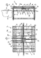
- a support frame 7 is provided with four cross members 8 adjacent to the transport device 4, which are equipped with four upwardly directed ball guides 9.
- the ball guides 9 and the uppermost contour of each ball lie in a common plane.
- the ball guides 4 therefore support the plate 3 in the position of the centering device 1 shown in FIGS. 1, 2 and 3. 4 makes it clear that in a starting position, namely, when the plate 3 is first retracted from the roller conveyor 5 in the direction of the arrow 6 in the centering device 1, the frame 7 with the ball guides 9 below the transport plane for the plate 3 is located, which is received within the frame 1 by a in Fig. 1 and 3, not shown, from FIGS. 2 and 4 but apparent conveyor belt 10 and transported in the direction of the arrows 11 in the centering device 1 in. If this is done, then the frame 7 is raised to the height shown in FIGS. 1 and 3, so that the ball guides 9 together form a supporting plane 12 for the plate 3.
- a support means in the form of a frame with three perpendicular to the supports 8 extending profile supports 13 is provided, which can be seen in detail in Fig. 8 and the following Fig.
- servo axes 14, 14a, 14b and 15 and 15a are arranged such that the strips surrounding the housing-like corresponding adjusting spindles lie below the carrier 13.
- the retaining strips 16 for these servo axes are, as Fig. 9 clearly shows, each attached to angle strips 17 of the carrier 13, which in turn are attached to cross members 18 at the upper edge of the frame 1.
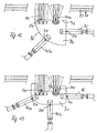
- each servo axis is provided in a conventional manner with an adjusting spindle and with an electric drive 22, with which it is possible, for example, on a nut of the spindle guided holder 23 (FIG. 9) between a first end position 23a and a second end position 23rd to move.
- the brackets 23 are each provided with stop rollers 24 which are fixed in the embodiment of Figs. 8, 9 and following with their axes fixed to the bracket 23, but even rotatably.
- the stop rollers 24 are indeed also connected to a slidable on the servo axes 14, 15 holder, but there not shown in detail pivot lever 25, with the help of the stop rollers 24 from the plane of the support plane 12 upwards can be without the servo axes 14, 15 must be moved to this.
- FIGS. 8 and 9, which is also retained in the following FIGS. 10 to 13, provides, as can also be seen in the drawings, the arrangement of the stop rollers 24 at much shorter guides.
- the arrangement is thus more stable, but requires that the servo axes 14, 15 including their carrier 13 and their associated carrier system can be raised up to the insertion process of the plates 3 in the centering - see Fig. 4 - not to hinder its retraction ,
- the lifting of the support system for the servo axes 14, 15 can be done in the same manner as is the case with the top of screen printing machines, one of which - not shown - the arrow direction III (Fig. 2) of the centering device 1 is arranged downstream ,
- Fig. 4 shows first, as already indicated, that during the retraction of the plate 3 in the centering both the ball guides 9 and the stop rollers 24 are moved out of lying on the lower edge of the plate 3 support level 12 up or down.
- the ball guides 9 are moved upwards, so that they, as previously stated, form the support plane 12 for the plate 3, which is therefore no longer on the conveyor belt 10.
- the stop rollers 24 are moved into the support plane 12, which takes place either in the embodiment of FIGS. 1 to 3 by pivoting the lever 25 or, in the embodiment of FIGS. 8 and 9 by lowering the carrier 13.
- the servo axes 14 and 15 are then actuated until the stop rollers 24, as shown in Fig. 5, abut against the outer contour of the plate 3 and fix it.
- This position is recorded by providing a torque pick-up device of the drive motors 22 of the servo shafts 14, 15, which can be done, for example, by detecting the current required to operate the motors 22.
- a pick-up device can operate very sensitively, so that with a corresponding increase in torque and the thus set position of the plate 3 in the centering clearly detected and, for example, by a balance of desired and actual positions an exact centering of the plate 3 allows regardless of any tolerances in the contour of the plate 3.
- the determined values of this approached end position can also be stored in a memory device and recalled for centering a subsequent plate.
- Fig. 6 shows that the plate 3 in its centered position from below by a transport device 26, for example, with suction cups 27, detected and transported in the direction of arrow 6 from the centering direction to the screen printing machine, not shown. These operations are shown in Fig. 6, where the suction cups 27 of the transport means 26 become active before the abutment rollers 24 are removed from the plate 3. Fig.
- FIGS. 8 and 10 to 13 show examples of plates 3, 3a, 3b and 3c having different outer contours which can be centered by the device according to the invention without any problems.
- 8 shows firstly that the servo axes 14 and 14a extend parallel to one another between the adjacent carriers 13 and that the servo axis 14b is arranged parallel to them on the opposite side. Not shown are perpendicular to extending servo axes, which serve to stop formation transverse to the direction of movement of the servo axes 14, 14a and 14b.
- the square plate 3 shown in Fig. 8 can be centered on the center of the centering device by the operation of the servo axes.
- the stop rollers 24 of the three servo axes are pressed for this purpose from opposite sides of the outer edges of the plate 3.
- the pressing of abutment rollers takes place at the sides perpendicular to the sides against which the abutment rollers 24 of the servo axes 14a and 14b abut the sides of the plate 3.
- FIG. 8 also makes it clear that plates up to the size 3 '- see the diagonal lines 29 - can be centered in the facility, if necessary.
- Fig. 10 shows e.g. the centering of a plate 3a with one-sided round contours.
- the centering is in principle in the same manner as that shown with reference to FIG. 8.
- the servo axes 14, 14a and 14b engage in opposite directions on the plate 3a in a direction of action, while the servo axes 15, 15a press their stop rollers 24 against the outer contour in a vertical direction of action.
- FIG. 13 shows a plate 3c with a recess contour 33 on which two abutment rollers 24 are applied by servo axes acting parallel to one another.
- the stop roller 24 acts on a servo axis 14b, and the page centering is performed by the stop rollers 24 of servo axes 15 and 15a, one of which is perpendicular to the direction of action of the servo axis 14b, the other at an angle to the axes of action of the other servo axes.
- the corresponding servo axis 15a then abuts with its stop roller 24 on the curved outer edge of the plate 3c.
Claims (12)
- Unité de centrage pour un dispositif de sérigraphie avec des rouleaux de butée (24) placés dans un plan de support (12) pour des plaques d'impression (3, 3a, 3b), lesquels viennent en contact avec le bord extérieur des plaques (3, 3a, 3b) et assurent ainsi leur position pour la poursuite du traitement,
caractérisée en ce que les rouleaux de butée (24) sont montés sur des servo-axes (14, 15) réglables en longueur qui se trouvent au-dessus du plan de support (12) et sont montés de leur côté sur des supports (13), qui sont disposés sur un châssis fixe (2) et au-dessus du plan de support (12). - Unité de centrage selon la revendication 1,
caractérisée en ce que les servo-axes (14, 15) sont montés de manière à pouvoir pivoter sur les supports (13), de façon à ce que leur direction d'action soit réglable. - Unité de centrage selon la revendication 1 ou 2,
caractérisée en ce que le couple de rotation des moteurs d'entraînement (22) des servo-axes (14, 15) est mesuré et utilisé pour définir la position des plaques. - Unité de centrage selon la revendication 3,
caractérisée en ce que la valeur du couple de rotation et la fonction d'entraînement des servo-axes (14, 15) sont enregistrées dans une unité de mémoire de manière à pouvoir être prélevées à nouveau. - Unité de centrage selon la revendication 1,
caractérisée en ce que les dimensions des plaques sont transmises par le biais d'un système DAO à un système de positionnement pour commander les servo-axes (14, 15) et enregistrées le cas échéant. - Unité de centrage selon la revendication 1,
caractérisée en ce que les supports (13) sont munis de trous (20) espacés les uns des autres et que les servo-axes (14, 15) sont munis de tiges (21, 28) pouvant être ancrées dans ceux-ci. - Unité de centrage selon la revendication 1,
caractérisée en ce qu'un chemin de transport (14) est prévu en amont du plan de support (12) et qu'une bande transporteuse (10) parallèle au chemin de transport lui est attribuée, depuis laquelle les plaques (3, 3a, 3b) peuvent être soulevées dans le plan de support (12) par un dispositif élévateur. - Unité de centrage selon la revendication 7,
caractérisée en ce que le dispositif élévateur est muni de plusieurs guides sphériques (9) placés dans un plan, qui peuvent être soulevés ensemble dans le plan de support (12) au-dessus du plan formé par la bande transporteuse (10). - Unité de centrage selon la revendication 1,
caractérisée en ce que les rouleaux de butée (24) sont en saillie d'un côté des servo-axes (14, 15). - Unité de centrage selon la revendication 9,
caractérisée en ce que les rouleaux de butée (24) sont disposés de manière à être réglables en distance par rapport aux servo-axes (14, 15). - Unité de centrage selon la revendication 10,
caractérisée en ce que les rouleaux de butée (24) sont disposés sur les servo-axes (14, 15).de manière à pouvoir pivoter, en particulier par des leviers de pivotement (25), - Unité de centrage selon la revendication 9,
caractérisée en ce que les rouleaux de butée (24) sont disposés de manière fixe avec leurs axes sur des éléments de fixation des servo-axes (14, 15) réglables et que les supports (13) pour les servo-axes (14, 15) font partie d'un cadre pouvant être levé ou baissé qui est prévu sur le dessus du châssis (2).
Applications Claiming Priority (3)
| Application Number | Priority Date | Filing Date | Title |
|---|---|---|---|
| DE10237038A DE10237038C1 (de) | 2002-08-08 | 2002-08-08 | Zentriereinrichtung für eine Siebdruckvorrichtung |
| DE10237038 | 2002-08-08 | ||
| PCT/EP2003/007558 WO2004018207A1 (fr) | 2002-08-08 | 2003-07-12 | Unite de centrage pour dispositif de serigraphie |
Publications (2)
| Publication Number | Publication Date |
|---|---|
| EP1526967A1 EP1526967A1 (fr) | 2005-05-04 |
| EP1526967B1 true EP1526967B1 (fr) | 2006-09-13 |
Family
ID=29225193
Family Applications (1)
| Application Number | Title | Priority Date | Filing Date |
|---|---|---|---|
| EP03792195A Expired - Lifetime EP1526967B1 (fr) | 2002-08-08 | 2003-07-12 | Unite de centrage pour dispositif de serigraphie |
Country Status (7)
| Country | Link |
|---|---|
| US (1) | US7284480B2 (fr) |
| EP (1) | EP1526967B1 (fr) |
| AT (1) | ATE339309T1 (fr) |
| AU (1) | AU2003257455A1 (fr) |
| DE (2) | DE10237038C1 (fr) |
| ES (1) | ES2271688T3 (fr) |
| WO (1) | WO2004018207A1 (fr) |
Families Citing this family (1)
| Publication number | Priority date | Publication date | Assignee | Title |
|---|---|---|---|---|
| US8215473B2 (en) * | 2008-05-21 | 2012-07-10 | Applied Materials, Inc. | Next generation screen printing system |
Family Cites Families (8)
| Publication number | Priority date | Publication date | Assignee | Title |
|---|---|---|---|---|
| US3918167A (en) * | 1974-03-01 | 1975-11-11 | Gerber Scientific Instr Co | Apparatus for sensing relative movement of a work table and tool |
| JPS57201657A (en) * | 1981-06-05 | 1982-12-10 | Seiko Epson Corp | Positioning mechanism for item to be printed |
| JP2614946B2 (ja) * | 1991-05-27 | 1997-05-28 | 日立テクノエンジニアリング株式会社 | スクリーン印刷機 |
| IT1283534B1 (it) | 1996-07-26 | 1998-04-21 | Aisa Spa | Macchina per la stampa serigrafica di lastre dotata di apparecchiatura di registrazione della posizione relativa tra la lastra e il retino |
| US6300971B1 (en) * | 1998-11-06 | 2001-10-09 | Gerber Systems Corporation | Apparatus and method for handling media sheets in a photo-plotter |
| IT1319173B1 (it) * | 2000-09-29 | 2003-09-26 | Engineering S R L Ag | Dispositivo e procedimento per posizionare un prodotto da decorare inuna macchina serigrafica. |
| DE10143563A1 (de) * | 2001-09-05 | 2003-03-27 | Nexpress Solutions Llc | Einrichtung zum Einstellen eines Druckmaschinenrahmens |
| US6561078B1 (en) * | 2001-12-28 | 2003-05-13 | Mark J. Hughes | Device for separating and removing kraeusen from beer during fermentation |
-
2002
- 2002-08-08 DE DE10237038A patent/DE10237038C1/de not_active Expired - Fee Related
-
2003
- 2003-07-12 EP EP03792195A patent/EP1526967B1/fr not_active Expired - Lifetime
- 2003-07-12 DE DE50305057T patent/DE50305057D1/de not_active Expired - Lifetime
- 2003-07-12 AU AU2003257455A patent/AU2003257455A1/en not_active Abandoned
- 2003-07-12 US US10/523,469 patent/US7284480B2/en active Active
- 2003-07-12 ES ES03792195T patent/ES2271688T3/es not_active Expired - Lifetime
- 2003-07-12 WO PCT/EP2003/007558 patent/WO2004018207A1/fr active IP Right Grant
- 2003-07-12 AT AT03792195T patent/ATE339309T1/de not_active IP Right Cessation
Also Published As
| Publication number | Publication date |
|---|---|
| US7284480B2 (en) | 2007-10-23 |
| ES2271688T3 (es) | 2007-04-16 |
| AU2003257455A1 (en) | 2004-03-11 |
| DE50305057D1 (de) | 2006-10-26 |
| WO2004018207A1 (fr) | 2004-03-04 |
| DE10237038C1 (de) | 2003-11-13 |
| US20060162587A1 (en) | 2006-07-27 |
| EP1526967A1 (fr) | 2005-05-04 |
| ATE339309T1 (de) | 2006-10-15 |
Similar Documents
| Publication | Publication Date | Title |
|---|---|---|
| DE60015853T2 (de) | Halterung für Reifen und Verfahren zum Greifen derselben | |
| DE60007226T2 (de) | Vorrichtung zum Zuführen von Platten | |
| DE3609086C2 (fr) | ||
| DE4339398C2 (de) | Dreheinrichtung für Transformator-Kernplatten | |
| DE3142378A1 (de) | "maschine zur selbsttaetigen montage von reifen auf felgen" | |
| DE60203081T2 (de) | Positionierungsvorrichtung für Bögen | |
| DE10047395A1 (de) | Bogentransportsystem für eine Rotationsdruckmaschine | |
| DE3515729A1 (de) | Platteneinschiebevorrichtung zum einschieben von auf einem hubtisch abgelegten plattenfoermigen werkstuecken in plattenaufteilanlagen | |
| EP1949982B1 (fr) | Dispositif de laminage et procédé d'enroulement de barrettes de liaison dans des profilés | |
| DE2751971C2 (fr) | ||
| EP0792814A1 (fr) | Machine de déballage de rouleaux, spécialement de rouleaux de papier d'imprimerie | |
| EP1181228A1 (fr) | Dispositif pour deposer des feuilles sur une pile | |
| EP1526967B1 (fr) | Unite de centrage pour dispositif de serigraphie | |
| DE3513754C1 (de) | Vorrichtung zum Aufsetzen von Deckeln auf Behaelter | |
| DE4315513C2 (de) | Einrichtung zur Formatanpassung einer Bogenübergabetrommel | |
| EP0227887A2 (fr) | Unité de chargement d'une bobine de papier sur un support de bobine de machine d'impression en creux | |
| DE1474184A1 (de) | Vorrichtung zum Ausrichten und Zufuehren von Belegen od.dgl. | |
| EP1520715B1 (fr) | Imprimante pour livres imprimant des documents de type livre | |
| DE3220489A1 (de) | Siebdruckmaschine | |
| EP0369162B1 (fr) | Imprimante comportant un poste d'impression basculant | |
| EP0597386B1 (fr) | Dispositif pour transférer des tÔles dans une installation de presse | |
| DE2821363C2 (de) | Einrichtung zum Aufstapeln von Blättern o.dgl. auf einer Palette sowie zum automatischen Entfernen der Blattstapel von der Stapelposition | |
| EP0629574A1 (fr) | Dispositif de chargement pour du matériau, en particulier pour des bobines de papier | |
| DE4439033C2 (de) | Bogenanleger | |
| EP1218271B1 (fr) | Dispositif pour tourner une pile de papier |
Legal Events
| Date | Code | Title | Description |
|---|---|---|---|
| PUAI | Public reference made under article 153(3) epc to a published international application that has entered the european phase |
Free format text: ORIGINAL CODE: 0009012 |
|
| 17P | Request for examination filed |
Effective date: 20050112 |
|
| AK | Designated contracting states |
Kind code of ref document: A1 Designated state(s): AT BE BG CH CY CZ DE DK EE ES FI FR GB GR HU IE IT LI LU MC NL PT RO SE SI SK TR |
|
| AX | Request for extension of the european patent |
Extension state: AL LT LV MK |
|
| DAX | Request for extension of the european patent (deleted) | ||
| GRAP | Despatch of communication of intention to grant a patent |
Free format text: ORIGINAL CODE: EPIDOSNIGR1 |
|
| GRAS | Grant fee paid |
Free format text: ORIGINAL CODE: EPIDOSNIGR3 |
|
| GRAA | (expected) grant |
Free format text: ORIGINAL CODE: 0009210 |
|
| AK | Designated contracting states |
Kind code of ref document: B1 Designated state(s): AT BE BG CH CY CZ DE DK EE ES FI FR GB GR HU IE IT LI LU MC NL PT RO SE SI SK TR |
|
| PG25 | Lapsed in a contracting state [announced via postgrant information from national office to epo] |
Ref country code: RO Free format text: LAPSE BECAUSE OF FAILURE TO SUBMIT A TRANSLATION OF THE DESCRIPTION OR TO PAY THE FEE WITHIN THE PRESCRIBED TIME-LIMIT Effective date: 20060913 Ref country code: IT Free format text: LAPSE BECAUSE OF FAILURE TO SUBMIT A TRANSLATION OF THE DESCRIPTION OR TO PAY THE FEE WITHIN THE PRESCRIBED TIME-LIMIT;WARNING: LAPSES OF ITALIAN PATENTS WITH EFFECTIVE DATE BEFORE 2007 MAY HAVE OCCURRED AT ANY TIME BEFORE 2007. THE CORRECT EFFECTIVE DATE MAY BE DIFFERENT FROM THE ONE RECORDED. Effective date: 20060913 Ref country code: GB Free format text: LAPSE BECAUSE OF FAILURE TO SUBMIT A TRANSLATION OF THE DESCRIPTION OR TO PAY THE FEE WITHIN THE PRESCRIBED TIME-LIMIT Effective date: 20060913 Ref country code: SK Free format text: LAPSE BECAUSE OF FAILURE TO SUBMIT A TRANSLATION OF THE DESCRIPTION OR TO PAY THE FEE WITHIN THE PRESCRIBED TIME-LIMIT Effective date: 20060913 Ref country code: SI Free format text: LAPSE BECAUSE OF FAILURE TO SUBMIT A TRANSLATION OF THE DESCRIPTION OR TO PAY THE FEE WITHIN THE PRESCRIBED TIME-LIMIT Effective date: 20060913 Ref country code: NL Free format text: LAPSE BECAUSE OF FAILURE TO SUBMIT A TRANSLATION OF THE DESCRIPTION OR TO PAY THE FEE WITHIN THE PRESCRIBED TIME-LIMIT Effective date: 20060913 Ref country code: IE Free format text: LAPSE BECAUSE OF FAILURE TO SUBMIT A TRANSLATION OF THE DESCRIPTION OR TO PAY THE FEE WITHIN THE PRESCRIBED TIME-LIMIT Effective date: 20060913 Ref country code: CZ Free format text: LAPSE BECAUSE OF FAILURE TO SUBMIT A TRANSLATION OF THE DESCRIPTION OR TO PAY THE FEE WITHIN THE PRESCRIBED TIME-LIMIT Effective date: 20060913 Ref country code: FI Free format text: LAPSE BECAUSE OF FAILURE TO SUBMIT A TRANSLATION OF THE DESCRIPTION OR TO PAY THE FEE WITHIN THE PRESCRIBED TIME-LIMIT Effective date: 20060913 |
|
| REG | Reference to a national code |
Ref country code: GB Ref legal event code: FG4D Free format text: NOT ENGLISH |
|
| REG | Reference to a national code |
Ref country code: CH Ref legal event code: EP |
|
| REG | Reference to a national code |
Ref country code: IE Ref legal event code: FG4D Free format text: LANGUAGE OF EP DOCUMENT: GERMAN |
|
| REF | Corresponds to: |
Ref document number: 50305057 Country of ref document: DE Date of ref document: 20061026 Kind code of ref document: P |
|
| PG25 | Lapsed in a contracting state [announced via postgrant information from national office to epo] |
Ref country code: SE Free format text: LAPSE BECAUSE OF FAILURE TO SUBMIT A TRANSLATION OF THE DESCRIPTION OR TO PAY THE FEE WITHIN THE PRESCRIBED TIME-LIMIT Effective date: 20061213 Ref country code: DK Free format text: LAPSE BECAUSE OF FAILURE TO SUBMIT A TRANSLATION OF THE DESCRIPTION OR TO PAY THE FEE WITHIN THE PRESCRIBED TIME-LIMIT Effective date: 20061213 Ref country code: BG Free format text: LAPSE BECAUSE OF FAILURE TO SUBMIT A TRANSLATION OF THE DESCRIPTION OR TO PAY THE FEE WITHIN THE PRESCRIBED TIME-LIMIT Effective date: 20061213 |
|
| ET | Fr: translation filed | ||
| PG25 | Lapsed in a contracting state [announced via postgrant information from national office to epo] |
Ref country code: PT Free format text: LAPSE BECAUSE OF FAILURE TO SUBMIT A TRANSLATION OF THE DESCRIPTION OR TO PAY THE FEE WITHIN THE PRESCRIBED TIME-LIMIT Effective date: 20070226 |
|
| NLV1 | Nl: lapsed or annulled due to failure to fulfill the requirements of art. 29p and 29m of the patents act | ||
| GBV | Gb: ep patent (uk) treated as always having been void in accordance with gb section 77(7)/1977 [no translation filed] |
Effective date: 20060913 |
|
| REG | Reference to a national code |
Ref country code: ES Ref legal event code: FG2A Ref document number: 2271688 Country of ref document: ES Kind code of ref document: T3 |
|
| REG | Reference to a national code |
Ref country code: IE Ref legal event code: FD4D |
|
| PLBE | No opposition filed within time limit |
Free format text: ORIGINAL CODE: 0009261 |
|
| STAA | Information on the status of an ep patent application or granted ep patent |
Free format text: STATUS: NO OPPOSITION FILED WITHIN TIME LIMIT |
|
| 26N | No opposition filed |
Effective date: 20070614 |
|
| REG | Reference to a national code |
Ref country code: CH Ref legal event code: PL |
|
| PG25 | Lapsed in a contracting state [announced via postgrant information from national office to epo] |
Ref country code: GR Free format text: LAPSE BECAUSE OF FAILURE TO SUBMIT A TRANSLATION OF THE DESCRIPTION OR TO PAY THE FEE WITHIN THE PRESCRIBED TIME-LIMIT Effective date: 20061214 Ref country code: LI Free format text: LAPSE BECAUSE OF NON-PAYMENT OF DUE FEES Effective date: 20070731 Ref country code: CH Free format text: LAPSE BECAUSE OF NON-PAYMENT OF DUE FEES Effective date: 20070731 Ref country code: MC Free format text: LAPSE BECAUSE OF NON-PAYMENT OF DUE FEES Effective date: 20070731 |
|
| PG25 | Lapsed in a contracting state [announced via postgrant information from national office to epo] |
Ref country code: EE Free format text: LAPSE BECAUSE OF FAILURE TO SUBMIT A TRANSLATION OF THE DESCRIPTION OR TO PAY THE FEE WITHIN THE PRESCRIBED TIME-LIMIT Effective date: 20060913 |
|
| PG25 | Lapsed in a contracting state [announced via postgrant information from national office to epo] |
Ref country code: AT Free format text: LAPSE BECAUSE OF NON-PAYMENT OF DUE FEES Effective date: 20070712 |
|
| PG25 | Lapsed in a contracting state [announced via postgrant information from national office to epo] |
Ref country code: CY Free format text: LAPSE BECAUSE OF FAILURE TO SUBMIT A TRANSLATION OF THE DESCRIPTION OR TO PAY THE FEE WITHIN THE PRESCRIBED TIME-LIMIT Effective date: 20060913 |
|
| PG25 | Lapsed in a contracting state [announced via postgrant information from national office to epo] |
Ref country code: HU Free format text: LAPSE BECAUSE OF FAILURE TO SUBMIT A TRANSLATION OF THE DESCRIPTION OR TO PAY THE FEE WITHIN THE PRESCRIBED TIME-LIMIT Effective date: 20070314 Ref country code: TR Free format text: LAPSE BECAUSE OF FAILURE TO SUBMIT A TRANSLATION OF THE DESCRIPTION OR TO PAY THE FEE WITHIN THE PRESCRIBED TIME-LIMIT Effective date: 20060913 |
|
| REG | Reference to a national code |
Ref country code: FR Ref legal event code: PLFP Year of fee payment: 14 |
|
| REG | Reference to a national code |
Ref country code: FR Ref legal event code: PLFP Year of fee payment: 15 |
|
| REG | Reference to a national code |
Ref country code: FR Ref legal event code: PLFP Year of fee payment: 16 |
|
| PGFP | Annual fee paid to national office [announced via postgrant information from national office to epo] |
Ref country code: LU Payment date: 20180723 Year of fee payment: 16 |
|
| PGFP | Annual fee paid to national office [announced via postgrant information from national office to epo] |
Ref country code: FR Payment date: 20180723 Year of fee payment: 16 Ref country code: IT Payment date: 20180720 Year of fee payment: 16 Ref country code: ES Payment date: 20180829 Year of fee payment: 16 Ref country code: DE Payment date: 20180725 Year of fee payment: 16 |
|
| PGFP | Annual fee paid to national office [announced via postgrant information from national office to epo] |
Ref country code: BE Payment date: 20180723 Year of fee payment: 16 |
|
| REG | Reference to a national code |
Ref country code: DE Ref legal event code: R119 Ref document number: 50305057 Country of ref document: DE |
|
| REG | Reference to a national code |
Ref country code: BE Ref legal event code: MM Effective date: 20190731 |
|
| PG25 | Lapsed in a contracting state [announced via postgrant information from national office to epo] |
Ref country code: DE Free format text: LAPSE BECAUSE OF NON-PAYMENT OF DUE FEES Effective date: 20200201 |
|
| PG25 | Lapsed in a contracting state [announced via postgrant information from national office to epo] |
Ref country code: BE Free format text: LAPSE BECAUSE OF NON-PAYMENT OF DUE FEES Effective date: 20190731 Ref country code: LU Free format text: LAPSE BECAUSE OF NON-PAYMENT OF DUE FEES Effective date: 20190712 |
|
| PG25 | Lapsed in a contracting state [announced via postgrant information from national office to epo] |
Ref country code: FR Free format text: LAPSE BECAUSE OF NON-PAYMENT OF DUE FEES Effective date: 20190731 |
|
| PG25 | Lapsed in a contracting state [announced via postgrant information from national office to epo] |
Ref country code: IT Free format text: LAPSE BECAUSE OF NON-PAYMENT OF DUE FEES Effective date: 20190712 |
|
| REG | Reference to a national code |
Ref country code: ES Ref legal event code: FD2A Effective date: 20201130 |
|
| PG25 | Lapsed in a contracting state [announced via postgrant information from national office to epo] |
Ref country code: ES Free format text: LAPSE BECAUSE OF NON-PAYMENT OF DUE FEES Effective date: 20190713 |