EP1526275A1 - Brennstoffeinspritzventil - Google Patents
Brennstoffeinspritzventil Download PDFInfo
- Publication number
- EP1526275A1 EP1526275A1 EP04105090A EP04105090A EP1526275A1 EP 1526275 A1 EP1526275 A1 EP 1526275A1 EP 04105090 A EP04105090 A EP 04105090A EP 04105090 A EP04105090 A EP 04105090A EP 1526275 A1 EP1526275 A1 EP 1526275A1
- Authority
- EP
- European Patent Office
- Prior art keywords
- elastic sealing
- fuel injection
- injection valve
- lifting element
- valve according
- Prior art date
- Legal status (The legal status is an assumption and is not a legal conclusion. Google has not performed a legal analysis and makes no representation as to the accuracy of the status listed.)
- Granted
Links
- 239000000446 fuel Substances 0.000 title claims abstract description 51
- 238000002347 injection Methods 0.000 title claims abstract description 34
- 239000007924 injection Substances 0.000 title claims abstract description 34
- 238000007789 sealing Methods 0.000 claims description 82
- 238000002485 combustion reaction Methods 0.000 claims description 7
- 229910000831 Steel Inorganic materials 0.000 claims description 5
- 239000010959 steel Substances 0.000 claims description 5
- 239000007788 liquid Substances 0.000 description 17
- 230000033001 locomotion Effects 0.000 description 11
- 230000004323 axial length Effects 0.000 description 3
- 230000008859 change Effects 0.000 description 3
- 230000008901 benefit Effects 0.000 description 2
- 230000001419 dependent effect Effects 0.000 description 2
- 239000012530 fluid Substances 0.000 description 2
- 238000004519 manufacturing process Methods 0.000 description 2
- 238000011161 development Methods 0.000 description 1
- 230000018109 developmental process Effects 0.000 description 1
- 230000000694 effects Effects 0.000 description 1
- 238000005516 engineering process Methods 0.000 description 1
- 238000000034 method Methods 0.000 description 1
- 230000008569 process Effects 0.000 description 1
- 230000009467 reduction Effects 0.000 description 1
- 229920002545 silicone oil Polymers 0.000 description 1
- 238000011144 upstream manufacturing Methods 0.000 description 1
Images


Classifications
-
- F—MECHANICAL ENGINEERING; LIGHTING; HEATING; WEAPONS; BLASTING
- F02—COMBUSTION ENGINES; HOT-GAS OR COMBUSTION-PRODUCT ENGINE PLANTS
- F02M—SUPPLYING COMBUSTION ENGINES IN GENERAL WITH COMBUSTIBLE MIXTURES OR CONSTITUENTS THEREOF
- F02M61/00—Fuel-injectors not provided for in groups F02M39/00 - F02M57/00 or F02M67/00
- F02M61/04—Fuel-injectors not provided for in groups F02M39/00 - F02M57/00 or F02M67/00 having valves, e.g. having a plurality of valves in series
- F02M61/08—Fuel-injectors not provided for in groups F02M39/00 - F02M57/00 or F02M67/00 having valves, e.g. having a plurality of valves in series the valves opening in direction of fuel flow
-
- F—MECHANICAL ENGINEERING; LIGHTING; HEATING; WEAPONS; BLASTING
- F02—COMBUSTION ENGINES; HOT-GAS OR COMBUSTION-PRODUCT ENGINE PLANTS
- F02M—SUPPLYING COMBUSTION ENGINES IN GENERAL WITH COMBUSTIBLE MIXTURES OR CONSTITUENTS THEREOF
- F02M51/00—Fuel-injection apparatus characterised by being operated electrically
- F02M51/06—Injectors peculiar thereto with means directly operating the valve needle
- F02M51/0603—Injectors peculiar thereto with means directly operating the valve needle using piezoelectric or magnetostrictive operating means
-
- F—MECHANICAL ENGINEERING; LIGHTING; HEATING; WEAPONS; BLASTING
- F02—COMBUSTION ENGINES; HOT-GAS OR COMBUSTION-PRODUCT ENGINE PLANTS
- F02M—SUPPLYING COMBUSTION ENGINES IN GENERAL WITH COMBUSTIBLE MIXTURES OR CONSTITUENTS THEREOF
- F02M2200/00—Details of fuel-injection apparatus, not otherwise provided for
- F02M2200/70—Linkage between actuator and actuated element, e.g. between piezoelectric actuator and needle valve or pump plunger
- F02M2200/703—Linkage between actuator and actuated element, e.g. between piezoelectric actuator and needle valve or pump plunger hydraulic
- F02M2200/705—Linkage between actuator and actuated element, e.g. between piezoelectric actuator and needle valve or pump plunger hydraulic with means for filling or emptying hydraulic chamber, e.g. for compensating clearance or thermal expansion
- F02M2200/706—Valves for filling or emptying hydraulic chamber
-
- F—MECHANICAL ENGINEERING; LIGHTING; HEATING; WEAPONS; BLASTING
- F02—COMBUSTION ENGINES; HOT-GAS OR COMBUSTION-PRODUCT ENGINE PLANTS
- F02M—SUPPLYING COMBUSTION ENGINES IN GENERAL WITH COMBUSTIBLE MIXTURES OR CONSTITUENTS THEREOF
- F02M2200/00—Details of fuel-injection apparatus, not otherwise provided for
- F02M2200/70—Linkage between actuator and actuated element, e.g. between piezoelectric actuator and needle valve or pump plunger
- F02M2200/703—Linkage between actuator and actuated element, e.g. between piezoelectric actuator and needle valve or pump plunger hydraulic
- F02M2200/707—Linkage between actuator and actuated element, e.g. between piezoelectric actuator and needle valve or pump plunger hydraulic with means for avoiding fuel contact with actuators, e.g. isolating actuators by using bellows or diaphragms
Definitions
- the invention relates to a fuel injection valve according to the preamble of the main claim.
- a fuel injection valve from US 4,858,439, which has a hydraulic coupler having a base body with two hollow cylinders, in each of which a piston is guided, and two acting as elastic sealing elements Wellbälge for sealing against the environment.
- the first bellows seals the coupler between the main body and the first piston and the second bellows seals the coupler between the main body and the second piston.
- a liquid-filled coupler gap is provided between the two pistons.
- a disadvantage is that the two corrugated bellows are mechanically heavily loaded when liquid exits through movement of the piston from the coupler gap, since the corrugated bellows must absorb the exiting from the coupler gap liquid as additional volume.
- the fuel injection valve according to the invention with the characterizing features of the main claim has In contrast, the advantage that in a simple way the mechanical load of the at least one elastic Sealing element is reduced by a lifting element is provided, that between the pot-shaped cylinder and an operatively connected to the piston head portion axially is movably mounted, with a seal between the Cylinder and the lifting element and between the lifting element and the head part is provided.
- the lifting element shifts when liquid emerges from the coupler gap and provides an additional Compensation volume available, so that at least one elastic sealing element over the prior art is subjected to a lower mechanical load.
- the Hydraulic coupler can do this with higher Inner pressures work, so that the fuel injector can be switched with higher frequency.
- a first elastic sealing element as a seal between the Lifting element and the cylinder and a second elastic Sealing element as a seal between the lifting element and the Headboard provided.
- an advantageous second embodiment is as Seal a stepped bellows provided, the one first sealing portion and a second sealing portion has, which has a trained as a lifting element shoulder are integrally connected. That way is a reduction in the manufacturing cost of the hydraulic Kopplers achievable.
- the head part Actively connected to the piston via a piston rod.
- first elastic Sealing element and the second elastic sealing element or the stepped bellows made of steel as a steel sealing element a hermetic seal of the hydraulic Kopplers over the life of the Ensures fuel injector.
- the first elastic sealing element or the first elastic Seal section a number of waves between three and eight. In this way, the stiffness of the first elastic Sealing element or the first elastic sealing portion and reduces its mechanical load.
- the second elastic sealing element or the second elastic Sealing section a wave number between three and twelve having. In this way, the rigidity of the second elastic sealing element or the second elastic Sealing section and reduced its mechanical stress.
- the lifting element is formed lid-shaped, since in this way space is saved.
- a coupler gap and between the lifting element and the cup-shaped cylinder is provided a compensation gap, wherein the coupler gap and the compensation gap over at least one throttle element are flow-connected. Due to the throttle element behaves the hydraulic Coupler for fast movements as a stiff component and at slow motions as flexible and length-compensating component.
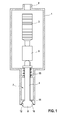
- FIG. 1 shows a schematically illustrated fuel injection valve
- FIG. 2 shows a hydraulic coupler according to the invention according to a first exemplary embodiment
- FIG. 3 shows a hydraulic coupler according to the invention according to a second exemplary embodiment
- FIG. 4 shows a hydraulic coupler according to the invention according to a third exemplary embodiment.
- FIG. 1 shows a fuel injection valve in which For example, an inventively trained hydraulic coupler is used.
- the fuel injection valve serves to fuel in to inject a combustion chamber of an internal combustion engine and For example, in the so-called direct injection used.
- the fuel injection valve has a valve housing 1 with an input channel 2 for the fuel.
- Valve housing 1 is a schematically illustrated actuator. 3 arranged for the axial adjustment of a valve needle 4.
- the valve needle 4 is axially movable in the valve housing 1 provided and has, for example, a the actuator. 3 facing needle shaft 7 and a the actuator 3 facing away Valve-closing body 8 on.
- the actuator 3 transmits his Movement via a so-called hydraulic coupler 9 the needle shaft 7 of the valve needle 4, whereby the with a Valve seat 10 cooperating valve closing body 8 the Fuel injector opens or closes.
- a fuel injection valve has one So-called ball-cone seat, wherein the valve seat 10th is formed, for example, cone-shaped and the Valve-closing body 8 a with the valve seat 10th having cooperating ball or radius section 11.
- sealing seat 12 When the fuel injection valve is closed is the Valve-closing body 8 over its entire circumference at the Valve seat 10 with line or surface contact tightly, what is referred to as sealing seat 12 below.
- the actuator 3 is for example a piezoelectric or magnetostrictive actuator and to the fuel encapsulated.
- a piezoelectric actuator is for example in the German Patent Application 103 19 599 proposed, wherein their content is expressly part of the disclosure of this Registration should be.
- the piezoelectric actuator 3 consists of a plurality of piezoceramic layers by applying a electrical tension an elongation in the axial direction To run.
- the so-called inverse exploited piezoelectric effect in which electrical Energy is converted into mechanical energy.
- the valve needle 4 By the application of the voltage generated stretching the piezoceramic layers is over the hydraulic Coupler 9 transferred to the valve needle 4, wherein the Valve needle 4, for example, a stroke of 40 to 50 Micrometer performs.
- a stroke of 40 to 50 Micrometer for example, a stroke of 40 to 50 Micrometer performs.
- the hydraulic must Coupler 9 the differences in the different Compensate for longitudinal expansion to ensure that the Fuel injection valve with the valve needle 4 independently from the respective temperature of the fuel injection valve executes the same stroke during an opening movement as the actuator 3. There must be no lifting losses, at where the stroke of the actuator 3 is not completely on the Valve needle 4 is transmitted, so that the stroke of Valve needle 4 is smaller than the stroke of the actuator.
- the fuel is in the valve housing 1 starting from the Input channel 2 to the valve closing body 8 upstream directed the sealing seat 12.
- Opening the Fuel injection valve lifts the valve closing body. 8 from the sealing seat 12, whereby a connection to the Combustion chamber of the engine is opened, so that Fuel via a between the valve closing body 8 and the valve seat 10 formed output gap in the combustion chamber flows.
- the output gap expands, for example in the flow direction and thereby acts as a diffuser. ever greater is the stroke of the valve needle 4 in the opening direction, the larger the output gap and the more fuel is injected into the combustion chamber per unit time.
- the fuel injection valve is for example a so-called outward-opening valve, wherein the Valve needle 4 a stroke in the direction away from the actuator 3 direction but can of course also a so-called to be inward opening valve.
- FIG. 2 shows a hydraulic coupler according to the invention according to a first embodiment.
- the hydraulic coupler 9 is between the actuator 3 and the Valve needle 4 clamped and has, for example, a cup-shaped cylinder 16 with a pot bottom 18 and a in the pot-shaped cylinder 16 axially movable piston 17th on.
- the pot bottom 18 of the pot-shaped cylinder 16 is applied the valve needle 4 on.
- the diameter of the piston 17th facing inside 20 of the cup-shaped cylinder 16 is slightly larger than the diameter of the piston 17th
- the piston 17 is for example cylindrical.
- On a side facing away from the bottom of the pot 18 21 of the Piston 17 is for example a piston rod 19th provided, the one with respect to the piston 17 smaller has radial expansion and in one of the piston 17th extending axially away.
- the piston rod 19 For example, is cylindrical, but can also have a different shape.
- the piston rod 19 has For example, at its end facing away from the piston 17 a on the piston rod 19 mounted head portion 31, the on the actuator 3 is applied.
- the head part 31 is for example cylindrical, but may also have a different shape exhibit.
- the head part 31 has a passage opening 32 on, in which the piston rod 19 at least protrudes, and is for example cohesively with the piston rod 19th connected.
- the head part 31 can also assembled in another way with the piston rod 19 be.
- a Hubelement 22 provided between the cup-shaped Cylinder 16 and the operatively connected to the piston 17 Head part 31 is mounted axially movable.
- the first embodiment is as a seal the hydraulic coupler 9, a first elastic Sealing element 23 between the lifting element 22 and the cylinder 16 and a second elastic sealing element 24 between the Hubelement 22 and the head part 31 with respect to the fuel provided in the fuel injection valve.
- the first elastic sealing element 23 and the second elastic Sealing element 24 are formed such that they Hubelement 22 enough degree of freedom for an axial Movement between the cup-shaped cylinder 16 and with the head 17 operatively connected to the piston 17.
- the lifting element 22 is, for example, lid-shaped formed and has a passage 29 through which the Piston rod 19 engages.
- the lifting element 22 is the axial movement, for example, on the piston rod 19th guided, wherein the passage channel 29 in its radial Extension is slightly larger than the piston rod 19th
- the lifting element 22 For example, a concentric with the passage 29th arranged guide shoulder 30, of the cylinder 16 facing away from the end of the lifting element 22, starting in runs away from the cylinder 16 direction.
- the first elastic sealing element 23 and / or the second elastic sealing element 24 are formed, for example, as corrugated bellows and a plurality of annular circumferential waves or folds 27 on.
- the first elastic sealing element 23 and the second elastic sealing element 24 are elastically formed in this way in the axial direction and made for example of steel.
- the first elastic sealing element 23 and the second elastic sealing element 24 have the lowest possible spring rigidity.
- the first elastic sealing element 23 has, for example, three to eight shafts 27, preferably five shafts 27, on, the second elastic sealing element 24 has a wave number of three to twelve, preferably nine. In this way, the respectively optimum for the function of the coupler stiffness of the elastic sealing elements 23,24 is achieved.
- a shaft 27 of two, for example, approximately parallel to each other running shaft walls 34 and the shaft walls 34 connecting wave arc 35 is formed.
- the wall thickness of the elastic sealing elements 23,24 is about 50 to 100 microns.
- the first elastic sealing element 23 has, for example, a wave height of three to six millimeters measured in the radial direction between two adjacent wave sheets 35, and the second elastic sealing element 24 has a wave height of one to two millimeters measured in the radial direction.
- the cylinder 16 has an annular on its outer circumference circumferential shoulder 25, which of the the lifting element 22nd facing end 21 of the cylinder 16 from up to one first shoulder 26 of the paragraph 25 runs.
- the first elastic sealing element 23 is with its one End with the first shoulder 26 of paragraph 25 and with its other end with the lifting element 22, for example whose circumference, materially or positively connected, for example by means of a welded joint, and will inside of the shoulder 25 axially guided.
- the second elastic sealing element 24 is at its one End with the guide shoulder 30, for example its Scope, of the lifting element 22 and at its other end with the head part 31 cohesively or non-positively connected, for example, with a designated inner mounting paragraph.
- a Spring element 33 for example a helical spring, arranged, with its one end on a front side of the Hubelements 22 and with its other end to a second Shoulder 36 of the head part 31 abuts and between the Lifting element 22 and the second shoulder 36 of the head part 31st Under tension is maintained.
- the cylinder 16, the piston 17, the piston rod 19, the Lifting element 22, the passageway 29 of the lifting element 22, the head part 31, the passage opening 32 of the head part 31, the first elastic sealing element 23, the second elastic Sealing element 24 and the spring element 33 are, for example concentric with an axis 37 of the hydraulic coupler 9 arranged.
- Coupler gap 38 Between the bottom of the pot 18 of the cylinder 16 and the Cup bottom 18 facing the front side of the piston 17 is a Coupler gap 38 and between the lifting element 22 and the End face 21 of the cylinder 16 a compensating gap 43 with provided a compensation volume.
- the size of the Coupler gap 38 is dependent on the axial position of the Piston 17 variable.
- the compensation gap 43 is over at least one provided in the piston 17 Connecting channel 44 and a to the connecting channel 44th subsequent throttle element 45 in the piston 17 with the Coupler gap 38 fluidly connected and vice versa.
- Connecting passage 44 extends, for example, of a Hubelement 22 facing end face of the piston 17th starting in the direction of the pot bottom 18 and is over the Throttling element 45 with the coupler gap 38th flow-connected.
- the hydraulic coupler 9 includes an interior 39, the by means of the elastic sealing elements 23,24 hermetically within the fuel injector over the Fuel is sealed.
- the interior 39 of the hydraulic coupler 9 is with a liquid For example, fuel or a secondary medium such as Silicone oil or Fomblin, filled.
- the spring element 33 presses the lifting element 22 in the direction of Cylinder 16 and generates in this way an overpressure in the interior 39 of the hydraulic coupler 9. Furthermore the spring element 33 presses the head part 31 in the direction of the Actuator 3.
- the Piston rod 19 For filling the hydraulic coupler 9, the Piston rod 19 a filling channel 46 which in the Interior 39 of the hydraulic coupler 9 opens. Of the Filling 46 is after filling the hydraulic Coupler 9 with liquid by means of a closure body 47, for example, a ball, compared to the fuel in Fuel injector sealed.
- a closure body 47 for example, a ball
- the hydraulic coupler 9 is similar to the different elongation resulting length difference, by changing its axial length such that the hydraulic coupler 9 with the head part 31 always on the Actuator 3 and with the bottom of the pot 18 always on the valve needle. 4 is applied. In this way it is achieved that no gap can form between the actuator 3 and the valve needle 4, so that is always guaranteed that the stroke of the actuator. 3 completely transferred to the valve needle 4 and no Lifting losses occur.
- the extension of the actuator 3 is via the head part 31, the Piston rod 19, the piston 17, the coupler gap 38 and the Cylinder 16 transferred to the valve needle 4.
- the hydraulic coupler 9 behaves as extremely stiff Component, since in the short time almost no liquid the coupler gap 38 through the throttle element 45 flow can.
- the coupler gap 38 remains constant, the Stroke of the actuator 3 completely on the valve needle. 4 transfer.
- the piston 17 moves with his Piston rod 19 and the head part 31 in from the bottom of the pot 18th turned away direction and thereby increases the coupler gap 38. It must be liquid from the compensation gap 43 and / or the rest of the interior 39 via the connecting channel 44 and the throttle element 45 flow into the coupler gap 38. Since the compensation gap 43 has given off liquid, he is by movement of the lifting element 22 in the direction of the cylinder 16 downsized. To the coupler gap 38 respectively completely filled with liquid as quickly as possible, so that no lifting losses can occur and the Fuel injection valve switched at high frequency can be, is the highest possible pressure of the liquid required in the hydraulic coupler 9. The overpressure the liquid in the hydraulic coupler 9 is for example 5 to 20 bar.
- the piston 17 moves with his Piston rod 19 and the head part 31 in the direction of the pot bottom 18th and thereby reduces the coupler gap 38. It must Liquid from the coupler gap 38 through the throttle element 45 and the connecting channel 44 in the compensation gap 43rd and / or the rest of the interior space 39. So the Compensation gap 43 absorb the additional liquid can, must the volume of the compensation gap 43 enlarge, by the lifting element 22 in from the cylinder 16th moved away.
- FIG 3 shows a hydraulic coupler according to the invention according to a second embodiment.
- the hydraulic coupler according to Figure 3 differs from the hydraulic coupler according to Figure 2 in that the sealing serving second elastic sealing element 24 has a greater number of shafts 27 than in the first embodiment. In this way, the rigidity of the second elastic sealing element 24 is reduced. Because of the higher number of waves 27 of the second elastic sealing element 24, the lifting element 22 is not guided on the piston rod 19, but on the inner side 20 of the cylinder 16. In addition, only a single throttle element 45 and a single connecting channel 44 is provided, wherein the connecting channel 44 and the filling channel 46 are arranged in alignment with each other and open into each other.
- the Through channel 29 compared to the first Embodiment executed enlarged radially outward, wherein the guide shoulder 30 of the lifting element 22 at the Cup bottom 18 facing end face is arranged and the Inside touching 20 into the cylinder 16 extends.
- the guide shoulder 30 is on an outer surface 50 slightly smaller than the diameter of the cylinder 16th on the inside 20.
- the guide shoulder 30 points at the Outer surface 50 at least one in the axial direction arranged groove 51 to the liquid volume in Area of the first elastic sealing element 23rd or the compensation gap 43 with the rest Fluid volume of the hydraulic coupler 9 to connect.
- the second elastic sealing element 24 extends from the Guide paragraph 30, starting through the passageway 29 to to the head portion 31 of the piston rod 19th
- FIG. 4 shows a hydraulic coupler according to the invention according to a third embodiment.
- the hydraulic coupler according to Figure 4 differs from the hydraulic coupler of Figure 3 and Figure 2 in that the lifting element 22 is not formed as a separate cover, but as a shoulder 56 of a stepped bellows 53.
- the stepped corrugated bellows 53 acts as an elastic sealing element and For example, it consists of a first elastic Sealing section 54, which seals the hydraulic Coupler 9 between the cylinder 16 and the lifting element 22nd achieved, from the lifting element 22 in the form of the shoulder 56 and from a second elastic sealing portion 55, the one Sealing of the hydraulic coupler 9 between the Lifting element 22 and the head part 31 causes.
- the stepped one Bellows 53 has in the first elastic sealing portion 54th and in the second elastic sealing portion 55 more annular circumferential waves or folds 27 on.
- the first sealing portion 54 is, for example, via the Hubelement 22 forming shoulder 56 with the second Sealing portion 55 integrally connected, wherein the diameter the first sealing portion 54, for example, larger is formed as the diameter of the second Sealing section 55.
- the first elastic sealing portion 54 has analogous to first elastic sealing element 23 according to the first and second embodiment, for example, a wave number between three and eight and the second elastic Sealing section 55 analogous to the second elastic Sealing element 24, for example, a wave number between three and twelve on.
- the lifting element 22 runs for example from a second sealing portion 55 facing outer shaft 27 of the first sealing portion 54 starting radially inwards and then to Connection with a first sealing portion 54th facing outer shaft 27 of the second sealing portion 55th in the axial direction.
- a bearing plate 57 for supporting the Spring element 33 is provided on the head part 31 facing the outer side of the Hubiatas 22 .
- the spring element 33 acts via the bearing plate 57 on the Hubefficiency 22 and generates this way an overpressure in the interior 39 of the hydraulic coupler 9.
- the stepped bellows 53 with the integrated lifting element 22nd can be produced more cost-effectively than separate Items 22,23,24 according to the first and second Embodiment still in an additional Manufacturing step must be connected together.
Landscapes
- Engineering & Computer Science (AREA)
- Chemical & Material Sciences (AREA)
- Combustion & Propulsion (AREA)
- Mechanical Engineering (AREA)
- General Engineering & Computer Science (AREA)
- Fuel-Injection Apparatus (AREA)
Abstract
Description
Es ist schon ein Brennstoffeinspritzventil aus der US 4,858,439 bekannt, das einen hydraulischen Koppler hat, der einen Grundkörper mit zwei Hohlzylindern, in denen jeweils ein Kolben geführt ist, und zwei als elastische Dichtelemente wirkende Wellbälge zur Abdichtung gegen die Umgebung aufweist. Der erste Wellbalg dichtet den Koppler zwischen dem Grundkörper und dem ersten Kolben ab und der zweite Wellbalg den Koppler zwischen dem Grundkörper und dem zweiten Kolben ab. Zwischen den beiden Kolben ist ein mit Flüssigkeit gefüllter Kopplerspalt vorgesehen. Nachteilig ist, daß die beiden Wellbälge mechanisch stark belastet werden, wenn Flüssigkeit durch Bewegung der Kolben aus dem Kopplerspalt austritt, da die Wellbälge die aus dem Kopplerspalt austretende Flüssigkeit als zusätzliches Volumen aufnehmen müssen.
Es zeigen Fig.1 ein schematisch dargestelltes Brennstoffeinspritzventil, Fig.2 einen erfindungsgemäßen hydraulischen Koppler gemäß einem ersten Ausführungsbeispiel, Fig.3 einen erfindungsgemäßen hydraulischen Koppler gemäß einem zweiten Ausführungsbeispiel und Fig.4 einen erfindungsgemäßen hydraulischen Koppler gemäß einem dritten Ausführungsbeispiel.
Das erste elastische Dichtelement 23 weist beispielsweise drei bis acht Wellen 27, vorzugsweise fünf Wellen 27, auf, das zweite elastische Dichtelement 24 hat eine Wellenanzahl von drei bis zwölf, vorzugsweise neun. Auf diese Weise wird die jeweils für die Funktion des Kopplers optimale Steifigkeit der elastischen Dichtelemente 23,24 erzielt. Dabei wird eine Welle 27 von zwei beispielsweise etwa parallel zueinander laufenden Wellenwänden 34 und einem die Wellenwände 34 verbindenden Wellenbogen 35 gebildet. Die Wandstärke der elastischen Dichtelemente 23,24 beträgt etwa 50 bis 100 Mikrometer. Das erste elastische Dichtelement 23 weist beispielsweise eine in radialer Richtung zwischen zwei benachbarten Wellenbogen 35 gemessene Wellenhöhe von drei bis sechs Millimetern und das zweite elastische Dichtelement 24 eine in radialer Richtung gemessene Wellenhöhe von ein bis zwei Millimetern auf.
Der hydraulische Koppler nach Fig.3 unterscheidet sich von dem hydraulischen Koppler nach Fig.2 darin, daß das der Abdichtung dienende zweite elastische Dichtelement 24 eine höhere Anzahl an Wellen 27 aufweist als beim ersten Ausführungsbeispiel. Auf diese Weise wird die Steifigkeit des zweiten elastischen Dichtelementes 24 verringert. Wegen der höheren Anzahl der Wellen 27 des zweiten elastischen Dichtelementes 24 wird das Hubelement 22 nicht an der Kolbenstange 19, sondern an der Innenseite 20 des Zylinders 16 geführt. Außerdem ist nur ein einziges Drosselelement 45 und ein einziger Verbindungskanal 44 vorgesehen, wobei der Verbindungskanal 44 und der Befüllkanal 46 fluchtend zueinander angeordnet sind und ineinander münden.
Der hydraulische Koppler nach Fig.4 unterscheidet sich von dem hydraulischen Koppler nach Fig.3 und Fig.2 darin, daß das Hubelement 22 nicht als separater Deckel, sondern als eine Schulter 56 eines gestuften Wellbalgs 53 ausgebildet ist.
Claims (12)
- Brennstoffeinspritzventil, insbesondere zum direkten Einspritzen von Kraftstoff in einen Brennraum einer Brennkraftmaschine, mit einem hydraulischen Koppler, der einen topfförmigen Zylinder und einen in dem topfförmigen Zylinder axial beweglichen Kolben aufweist, dadurch gekennzeichnet, dass ein Hubelement (22) vorgesehen ist, das zwischen dem topfförmigen Zylinder (16) und einem mit dem Kolben (17) wirkverbundenen Kopfteil (31) axial beweglich gelagert ist, wobei eine Abdichtung zwischen dem Zylinder (16) und dem Hubelement (22) und zwischen dem Hubelement (22) und dem Kopfteil (31) vorgesehen ist.
- Brennstoffeinspritzventil nach Anspruch 1, dadurch gekennzeichnet, dass ein erstes elastisches Dichtelement (23) als Abdichtung zwischen dem Hubelement (22) und dem Zylinder (16) und ein zweites elastisches Dichtelement (24) als Abdichtung zwischen dem Hubelement (22) und dem Kopfteil (31) vorgesehen ist.
- Brennstoffeinspritzventil nach Anspruch 1, dadurch gekennzeichnet, dass als Abdichtung ein gestufter Wellbalg (53) vorgesehen ist, der einen ersten elastischen Dichtabschnitt (54) und einen zweiten elastischen Dichtabschnitt (55) aufweist, die über eine als Hubelement (22) ausgebildete Schulter (56) einteilig miteinander verbunden sind.
- Brennstoffeinspritzventil nach Anspruch 2, dadurch gekennzeichnet, dass das erste elastische Dichtelement (23) und das zweite elastische Dichtelement (24) als Wellbalg mit einer oder mehreren Wellen (27) ausgebildet ist.
- Brennstoffeinspritzventil nach einem der Ansprüche 2 oder 3, dadurch gekennzeichnet, dass das Kopfteil (31) über eine Kolbenstange (19) mit dem Kolben (17) wirkverbunden ist.
- Brennstoffeinspritzventil nach einem der Ansprüche 2 oder 3, dadurch gekennzeichnet, dass das erste elastische Dichtelement (23) und das zweite elastische Dichtelement (24) oder der gestufte Wellbalg (53) aus Stahl hergestellt sind.
- Brennstoffeinspritzventil nach einem der Ansprüche 2 oder 3, dadurch gekennzeichnet, dass das erste elastische Dichtelement (23) oder der erste elastische Dichtabschnitt (54) eine Wellenanzahl zwischen drei und acht aufweist.
- Brennstoffeinspritzventil nach einem der Ansprüche 2 oder 3, dadurch gekennzeichnet, dass das zweite elastische Dichtelement (24) oder der zweite elastische Dichtabschnitt (55) eine Wellenanzahl zwischen drei und zwölf aufweist.
- Brennstoffeinspritzventil nach einem der Ansprüche 2 oder 3, dadurch gekennzeichnet, dass ein Federelement (33) zwischen dem Hubelement (22) und dem Kopfteil (31) angeordnet ist.
- Brennstoffeinspritzventil nach Anspruch 2, dadurch gekennzeichnet, dass das Hubelement (22) einen Führungsabsatz (30) aufweist, der entlang der Kolbenstange (19) und/oder entlang dem Zylinder (16) axial geführt ist.
- Brennstoffeinspritzventil nach Anspruch 2, dadurch gekennzeichnet, dass das Hubelement (22) deckelförmig ausgebildet ist.
- Brennstoffeinspritzventil nach einem der Ansprüche 2 oder 3, dadurch gekennzeichnet, dass zwischen dem Zylinder (16) und dem Kolben (17) ein Kopplerspalt (38) und zwischen dem Hubelement (22) und dem topfförmigen Zylinder (16) ein Ausgleichsspalt (43) vorgesehen ist, wobei der Kopplerspalt (38) und der Ausgleichsspalt (43) über zumindest ein Drosselelement (45) strömungsverbunden sind.
Applications Claiming Priority (4)
| Application Number | Priority Date | Filing Date | Title |
|---|---|---|---|
| DE10348775 | 2003-10-21 | ||
| DE10348775 | 2003-10-21 | ||
| DE102004015622A DE102004015622A1 (de) | 2003-10-21 | 2004-03-31 | Brennstoffeinspritzventil |
| DE102004015622 | 2004-03-31 |
Publications (2)
| Publication Number | Publication Date |
|---|---|
| EP1526275A1 true EP1526275A1 (de) | 2005-04-27 |
| EP1526275B1 EP1526275B1 (de) | 2007-01-10 |
Family
ID=34395061
Family Applications (1)
| Application Number | Title | Priority Date | Filing Date |
|---|---|---|---|
| EP20040105090 Expired - Fee Related EP1526275B1 (de) | 2003-10-21 | 2004-10-15 | Brennstoffeinspritzventil |
Country Status (2)
| Country | Link |
|---|---|
| EP (1) | EP1526275B1 (de) |
| DE (1) | DE502004002606D1 (de) |
Cited By (1)
| Publication number | Priority date | Publication date | Assignee | Title |
|---|---|---|---|---|
| US20150014436A1 (en) * | 2012-02-27 | 2015-01-15 | Robert Bosch Gmbh | Valve for Metering Fluid |
Citations (5)
| Publication number | Priority date | Publication date | Assignee | Title |
|---|---|---|---|---|
| US4858439A (en) * | 1987-03-03 | 1989-08-22 | Toyota Jidosha Kabushiki Kaisha | Device for varying a stroke |
| WO2001029403A1 (de) * | 1999-10-21 | 2001-04-26 | Robert Bosch Gmbh | Brennstoffeinspritzventil |
| EP1111230A2 (de) * | 1999-12-22 | 2001-06-27 | Siemens Aktiengesellschaft | Hydraulische Vorrichtung zum Übertragen einer Aktorbewegung |
| DE10030232A1 (de) * | 2000-06-20 | 2002-01-17 | Siemens Ag | Vorrichtung zum Übertragen einer Bewegung mit Spielausgleich |
| WO2003031799A1 (de) * | 2001-10-02 | 2003-04-17 | Robert Bosch Gmbh | Brennstoffeinspritzventil |
-
2004
- 2004-10-15 EP EP20040105090 patent/EP1526275B1/de not_active Expired - Fee Related
- 2004-10-15 DE DE200450002606 patent/DE502004002606D1/de active Active
Patent Citations (5)
| Publication number | Priority date | Publication date | Assignee | Title |
|---|---|---|---|---|
| US4858439A (en) * | 1987-03-03 | 1989-08-22 | Toyota Jidosha Kabushiki Kaisha | Device for varying a stroke |
| WO2001029403A1 (de) * | 1999-10-21 | 2001-04-26 | Robert Bosch Gmbh | Brennstoffeinspritzventil |
| EP1111230A2 (de) * | 1999-12-22 | 2001-06-27 | Siemens Aktiengesellschaft | Hydraulische Vorrichtung zum Übertragen einer Aktorbewegung |
| DE10030232A1 (de) * | 2000-06-20 | 2002-01-17 | Siemens Ag | Vorrichtung zum Übertragen einer Bewegung mit Spielausgleich |
| WO2003031799A1 (de) * | 2001-10-02 | 2003-04-17 | Robert Bosch Gmbh | Brennstoffeinspritzventil |
Cited By (2)
| Publication number | Priority date | Publication date | Assignee | Title |
|---|---|---|---|---|
| US20150014436A1 (en) * | 2012-02-27 | 2015-01-15 | Robert Bosch Gmbh | Valve for Metering Fluid |
| US9470198B2 (en) * | 2012-02-27 | 2016-10-18 | Robert Bosch Gmbh | Valve for metering fluid |
Also Published As
| Publication number | Publication date |
|---|---|
| EP1526275B1 (de) | 2007-01-10 |
| DE502004002606D1 (de) | 2007-02-22 |
Similar Documents
| Publication | Publication Date | Title |
|---|---|---|
| DE60121352T2 (de) | Ausgleichvorrichtung mit einer flexiblen membran für ein kraftstoffeinspritzventil und verfahren dafür | |
| DE4306073C1 (de) | Zumeßvorrichtung für Fluide | |
| EP1497553B1 (de) | Dosiervorrichtung für fluide, insbesondere kraftfahrzeug-einspritzventil | |
| DE102009015738B4 (de) | Hydraulischer Hubübersetzer und Injektor zur Dossierung von Fluiden | |
| DE4119467A1 (de) | Vorrichtung zur kraft- und hubuebersetzung bzw. -uebertragung | |
| EP1593841B1 (de) | Brennstoffeinspritzventil | |
| DE102005028400A1 (de) | Kraftstoffeinspritzvorrichtung für ein Kraftstoffeinspritzsystem | |
| DE10140799A1 (de) | Brennstoffeinspritzventil | |
| DE10217594A1 (de) | Brennstoffeinspritzventil | |
| WO2003106837A1 (de) | Dosiervorrichtung für fluide, insbesondere kraftfahrzeug-einspritzventil | |
| EP1456526A1 (de) | Brennstoffeinspritzventil | |
| EP1538331B1 (de) | Brennstoffeinspritzventil | |
| DE102004015622A1 (de) | Brennstoffeinspritzventil | |
| EP1714026B1 (de) | Brennstoffeinspritzventil | |
| DE10360449A1 (de) | Brennstoffeinspritzventil | |
| EP1526275B1 (de) | Brennstoffeinspritzventil | |
| DE102004002134A1 (de) | Brennstoffeinspritzventil | |
| EP1519036B1 (de) | Brennstoffeinspritzventil | |
| EP1488096B1 (de) | Brennstoffeinspritzventil | |
| DE10353641B4 (de) | Brennstoffeinspritzventil | |
| EP1452727B1 (de) | Brennstoffeinspritzventil | |
| DE102004060533A1 (de) | Brennstoffeinspritzventil | |
| DE102004002081A1 (de) | Brennstoffeinspritzventil | |
| DE10123174B4 (de) | Ventil zum Steuern von Flüssigkeiten | |
| EP1752654A1 (de) | Brennstoffeinspritzventil |
Legal Events
| Date | Code | Title | Description |
|---|---|---|---|
| PUAI | Public reference made under article 153(3) epc to a published international application that has entered the european phase |
Free format text: ORIGINAL CODE: 0009012 |
|
| AK | Designated contracting states |
Kind code of ref document: A1 Designated state(s): AT BE BG CH CY CZ DE DK EE ES FI FR GB GR HU IE IT LI LU MC NL PL PT RO SE SI SK TR |
|
| AX | Request for extension of the european patent |
Extension state: AL HR LT LV MK |
|
| 17P | Request for examination filed |
Effective date: 20051027 |
|
| AKX | Designation fees paid |
Designated state(s): DE FR GB IT |
|
| GRAP | Despatch of communication of intention to grant a patent |
Free format text: ORIGINAL CODE: EPIDOSNIGR1 |
|
| GRAS | Grant fee paid |
Free format text: ORIGINAL CODE: EPIDOSNIGR3 |
|
| GRAA | (expected) grant |
Free format text: ORIGINAL CODE: 0009210 |
|
| AK | Designated contracting states |
Kind code of ref document: B1 Designated state(s): DE FR GB IT |
|
| REG | Reference to a national code |
Ref country code: GB Ref legal event code: FG4D Free format text: NOT ENGLISH |
|
| REF | Corresponds to: |
Ref document number: 502004002606 Country of ref document: DE Date of ref document: 20070222 Kind code of ref document: P |
|
| GBT | Gb: translation of ep patent filed (gb section 77(6)(a)/1977) |
Effective date: 20070416 |
|
| ET | Fr: translation filed | ||
| PLBE | No opposition filed within time limit |
Free format text: ORIGINAL CODE: 0009261 |
|
| STAA | Information on the status of an ep patent application or granted ep patent |
Free format text: STATUS: NO OPPOSITION FILED WITHIN TIME LIMIT |
|
| 26N | No opposition filed |
Effective date: 20071011 |
|
| REG | Reference to a national code |
Ref country code: FR Ref legal event code: PLFP Year of fee payment: 12 |
|
| REG | Reference to a national code |
Ref country code: FR Ref legal event code: PLFP Year of fee payment: 13 |
|
| REG | Reference to a national code |
Ref country code: FR Ref legal event code: PLFP Year of fee payment: 14 |
|
| PGFP | Annual fee paid to national office [announced via postgrant information from national office to epo] |
Ref country code: FR Payment date: 20171023 Year of fee payment: 14 |
|
| PGFP | Annual fee paid to national office [announced via postgrant information from national office to epo] |
Ref country code: GB Payment date: 20171024 Year of fee payment: 14 Ref country code: IT Payment date: 20171020 Year of fee payment: 14 |
|
| PGFP | Annual fee paid to national office [announced via postgrant information from national office to epo] |
Ref country code: DE Payment date: 20181206 Year of fee payment: 15 |
|
| GBPC | Gb: european patent ceased through non-payment of renewal fee |
Effective date: 20181015 |
|
| PG25 | Lapsed in a contracting state [announced via postgrant information from national office to epo] |
Ref country code: FR Free format text: LAPSE BECAUSE OF NON-PAYMENT OF DUE FEES Effective date: 20181031 |
|
| PG25 | Lapsed in a contracting state [announced via postgrant information from national office to epo] |
Ref country code: IT Free format text: LAPSE BECAUSE OF NON-PAYMENT OF DUE FEES Effective date: 20181015 Ref country code: GB Free format text: LAPSE BECAUSE OF NON-PAYMENT OF DUE FEES Effective date: 20181015 |
|
| REG | Reference to a national code |
Ref country code: DE Ref legal event code: R119 Ref document number: 502004002606 Country of ref document: DE |
|
| PG25 | Lapsed in a contracting state [announced via postgrant information from national office to epo] |
Ref country code: DE Free format text: LAPSE BECAUSE OF NON-PAYMENT OF DUE FEES Effective date: 20200501 |