EP1526237B1 - Dispositif pour verrouillage et pour actionner des capotes, portes ou similaires - Google Patents
Dispositif pour verrouillage et pour actionner des capotes, portes ou similaires Download PDFInfo
- Publication number
- EP1526237B1 EP1526237B1 EP04020366A EP04020366A EP1526237B1 EP 1526237 B1 EP1526237 B1 EP 1526237B1 EP 04020366 A EP04020366 A EP 04020366A EP 04020366 A EP04020366 A EP 04020366A EP 1526237 B1 EP1526237 B1 EP 1526237B1
- Authority
- EP
- European Patent Office
- Prior art keywords
- handle
- flap
- spring element
- housing
- plunger
- Prior art date
- Legal status (The legal status is an assumption and is not a legal conclusion. Google has not performed a legal analysis and makes no representation as to the accuracy of the status listed.)
- Expired - Lifetime
Links
- 230000000903 blocking effect Effects 0.000 description 6
- 230000001419 dependent effect Effects 0.000 description 1
- 238000006073 displacement reaction Methods 0.000 description 1
- 239000012634 fragment Substances 0.000 description 1
- 238000003780 insertion Methods 0.000 description 1
- 230000037431 insertion Effects 0.000 description 1
- 230000003993 interaction Effects 0.000 description 1
- 238000004519 manufacturing process Methods 0.000 description 1
- 230000000284 resting effect Effects 0.000 description 1
- 239000007787 solid Substances 0.000 description 1
- 241000894007 species Species 0.000 description 1
- 230000007704 transition Effects 0.000 description 1
Images


Classifications
-
- E—FIXED CONSTRUCTIONS
- E05—LOCKS; KEYS; WINDOW OR DOOR FITTINGS; SAFES
- E05B—LOCKS; ACCESSORIES THEREFOR; HANDCUFFS
- E05B77/00—Vehicle locks characterised by special functions or purposes
-
- E—FIXED CONSTRUCTIONS
- E05—LOCKS; KEYS; WINDOW OR DOOR FITTINGS; SAFES
- E05C—BOLTS OR FASTENING DEVICES FOR WINGS, SPECIALLY FOR DOORS OR WINDOWS
- E05C3/00—Fastening devices with bolts moving pivotally or rotatively
- E05C3/12—Fastening devices with bolts moving pivotally or rotatively with latching action
- E05C3/16—Fastening devices with bolts moving pivotally or rotatively with latching action with operating handle or equivalent member moving otherwise than rigidly with the latch
- E05C3/22—Fastening devices with bolts moving pivotally or rotatively with latching action with operating handle or equivalent member moving otherwise than rigidly with the latch the bolt being spring controlled
- E05C3/24—Fastening devices with bolts moving pivotally or rotatively with latching action with operating handle or equivalent member moving otherwise than rigidly with the latch the bolt being spring controlled in the form of a bifurcated member
-
- E—FIXED CONSTRUCTIONS
- E05—LOCKS; KEYS; WINDOW OR DOOR FITTINGS; SAFES
- E05C—BOLTS OR FASTENING DEVICES FOR WINGS, SPECIALLY FOR DOORS OR WINDOWS
- E05C5/00—Fastening devices with bolts moving otherwise than only rectilinearly and only pivotally or rotatively
- E05C5/02—Fastening devices with bolts moving otherwise than only rectilinearly and only pivotally or rotatively both moving axially and turning about their axis to secure the wing
- E05C5/04—Fastening devices with bolts moving otherwise than only rectilinearly and only pivotally or rotatively both moving axially and turning about their axis to secure the wing performing both movements simultaneously, e.g. screwing into a keeper
Definitions
- the device comprises a bolt which is pressed by a return spring in a locking position and engages behind an arranged outside the flap stationary shoulder.
- the device also includes a handle having an inner end and an outer end and is held by a spring force in a rest position in the housing.
- a handle having an inner end and an outer end and is held by a spring force in a rest position in the housing.
- the control means consist of a two-armed, in turn spring-loaded pawl, one of them Pawl arm cooperates with a cam on the handle, while the other ratchet arm is supported in the blocking position on a shoulder of a trained as a rotary latch bolt.
- the catch detects a web acting as a stationary shoulder web of a striker.
- Space-saving is a device specified in the preamble of claim 1 Art (DE 35 32 152 C1), because there is the pivotal movement of the handle between the rest position and intermediate layer on the one hand and between the liner and working position on the other hand by two spaced pivot axes and thereby during actuation the handle produces two different lever arm lengths.
- this known device for two physically different axle bolts are provided, of which one bolt is rotatably mounted in a firmly connected to the handle tab, while the other axle is received in a bearing block located in the housing.
- This bracket is also used for pivotal mounting of a trained as a rotatable hook latch.
- the two axle bolts are interconnected by a tab, by means of which a different pivoting operation of the handle is possible.
- the handle rotates about a first axis, which is determined by the axle pin on the flap of the handle. This is done by manual pressure on the outer end of the handle. Then there is a short lever arm length. The inner end of the handle is pivoted out of the housing and can then be easily grasped by the hand. Upon further pivoting the handle is transferred from its intermediate position in its working position, where a second, formed by the other axle pivot axis is effective. In this second pivoting movement, both the handle-side first axle pin and the tab is pivoted with. Then the handle acts only as a one-armed lever with a large lever length and acting as a bar pivoting hooks then releases a stationary shoulder in the vehicle. This device still requires several elements, namely two axle bolts and tabs for connecting the two axle bolts.
- the invention has for its object to simplify the known device referred to in the preamble of claim 1 species without jeopardizing the reliability of locking and operating the handle. This is inventively achieved by the measures mentioned in claim 1, which has the following special significance.
- the invention requires only a single axle, which is assigned to the storage and management only one slot.
- two different pivot axes during the initial phase and the final phase of the operation of the handle achieves the invention simply by the fact that the axle bolt automatically enters two mutually different sections of the slot.
- the initial operation of the handle from the rest position in the intermediate position of the axle is in an initial portion of the slot, where the first pivot axis is formed.
- the handle pin Upon further actuation of the handle from the intermediate position in the working position of the axle pin enters an end portion of the slot, where then the second pivot axis is generated for the handle.
- This saves components, eliminating their manufacture and assembly in the device. Because of the omitted components, the dimensions of the housing can be further reduced in the inventive device. This will save space in the cargo compartment under the hatch.
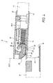
- the first device 10 according to the invention shown in FIGS. 1 to 4 is installed at the free end of a flap 11, of which only a fragment is illustrated in phantom.
- the flap 11 is in a different components of the device 10 receiving two-piece housing 12, 13 integrated.
- the upper housing part 12 is a latch 20 which is formed in the present case as a slide and in the housing in the direction of the double arrow 21 is longitudinally movable.
- the inner end of the slide 22 is spring-loaded by a return spring 14 in the sense of the force arrow 15 and thereby normally pushed out of the housing 12, 13.
- the locking end 22 from the slider 20 then engages behind a stationary shoulder 16 of a solidified vehicle bottom 17 located in the dash-dot solid locking piece 18.
- the slider 20 is in its clarified by an auxiliary line 20.1 blocking position shown in FIG. 1.
- In the vehicle floor 17 is also still a stationary Support surface 19 is provided, on which the closed flap 11 is supported with the underside of the housing bottom 13.
- the blocking position 20.1 of the slider 20 is determined by internal stops, against which the restoring force 15 acts.
- a plunger 40 shown in Fig. 1 which is integrally formed with a flexible tongue 23 is suitable.
- the tongue 23 generates an integrated in the slider 20 spring member.
- the plunger 40 is supported in Fig. 1, inter alia, with its outer edge on a shoulder 24 in the bottom portion 58 of the upper housing part 12 from.
- the plunger 40 is yet another, later to be described in detail function.
- the shoulder 24 is formed here by the inner edge of an opening 25 in the bottom region of the housing upper part 12. Under the eruption 25 is also an opening 26 in the housing bottom thirteenth
- a handle 30 is pivotally mounted in a special way.
- the handle comprises two, as outer end 31 and inner end 32 to be described in more detail end portions and is held by a spring force 35 in an illustrated by the auxiliary line 30.0 in Fig. 1 rest position.
- the spring force 35 is generated by a between the inside of the handle 30 and the upper housing part 12 with its two legs supporting leg spring 34.
- the handle 30 In the rest position 30.0, the handle 30 is with its outer side substantially flush with the surface of the upper housing part 12th
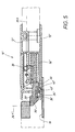
- Fig. 2 is used to support the handle 30, a single pivot pin 27 which is received in a bearing block 44 from the upper housing part 12.
- the axle 27 passes through a slot 37 and is located in a seated on the underside of the handle 30 like a rib downwardly projecting tabs 33. It could, at a distance from each other, two such tabs 33 may be provided on the handle 30, in which two ends of the same Protruding axle pin 27.
- the axle pin 27 is in a first portion 38 of the slot 37 and thus determines a 41 marked in Fig. 2 first pivot axis position with respect to the handle 30.
- This section 38 of the slot 37 is at the same time the one end portion of the circle segment 37, the now acts as the first bearing eye for the axle 27 and should therefore be called "initial section".
- the first pivot axis 41 determines a two-armedness of the handle 30 with the two mutually oppositely directed lever arms 51, 52.
- the lever arm 51 is pivoted downward, whereby the other lever arm 52 comes out of the upper housing part 12. Then there provided a handle point 36 for the tips of the hand 47 of the human hand 45 is easily accessible.
- the handle 30, which is pivoted about the axis 41, is located in an intermediate layer 30.1 illustrated by the auxiliary line 30.1.
- the handle 30 provided on the underside of the handle 30 approach 49 in the region of a hollow section 29 from the slider 20, whereby the slider 20 initially still remains in its described locking position 20.1.
- the flap 11 is still locked against the vehicle floor 17.
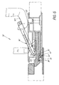
- the pivot axis 42 is offset in the handle 30 to the aforementioned length 55 relative to the first axis 41.
- the handle 30 now acts as a one-armed lever 50.
- the achieved in Fig. 3 pivoting position 30.2 of Fig. 3 is still the following special closing technical significance.
- the latch 20 is retracted via its web 59 from the handle-side projection 49 into the housing 12, 13 against the restoring force 15 acting on it during the final phase 54 of the pivoting operation and releases the stationary shoulder 16 in the vehicle floor 17.
- the slider 20 is then in the, in Fig. 3 20.2 marked release position.
- the flap 11 can now be opened in the sense of the raising arrow 56 of FIG. 3 via the handle point 36, which reliably detects the grip point 36 from the handle 30.
- FIGS. 5 to 7 a second exemplary embodiment 10 'of the device according to the invention is shown in FIGS. 5 to 7.
- the same reference numerals have been used. In that regard, the previous description applies. All it takes is a discussion of the differences.
- a plunger 40 'instead of the slider 20' is made of a counter-spring member 60 formed on the housing.
- This counter spring member 60 is formed by a gap in the bottom portion 58 'of the upper housing part 12' in Fig. 5 at the point where the outbreak 25 was provided in the corresponding bottom portion 58 of the first device 10 of FIG.
- the counter-spring member 60 is formed in the manner of a tongue and should therefore, for the purpose of distinguishing the slide-side tongue 23 'are referred to as "counter-tongue".
- the tongue 23 'of the device 10' thus has a smooth bottom, without plunger.
- Fig. 5 shows again, analogous to FIG. 1, the rest position 30.0 of the handle 30 on the one hand and the locking position 20.1 'of the slider 20' on the other.
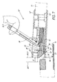
- ram end 43 ' located on the opposite tongue 60 ram end 43 'is supported on the stationary support surface 19 and bends not only its own counter-tongue 60, but also the slide-side tongue 23' arranged above it.
- FIG. 6 corresponds to the device 10 'to the conditions in FIG. 2 of the device 10 described above.
- the described intermediate position 30.1 of the handle lies 30 before.
- the tongue 23 'and the counter-tongue 60 take, in analogy to Fig. 2, the same positions as in Fig. 5 in the device 10' a. This changes only in FIG. 7.
Landscapes
- Engineering & Computer Science (AREA)
- Mechanical Engineering (AREA)
- Steering Devices For Bicycles And Motorcycles (AREA)
- Lock And Its Accessories (AREA)
- Pinball Game Machines (AREA)
- Coin-Freed Apparatuses For Hiring Articles (AREA)
Claims (13)
- Dispositif (10) servant à verrouiller et actionner des capotes (11), portes ou assimilées, notamment sur des véhicules,
avec un boîtier (12, 13) en assise dans la capote (11),
avec un verrou (20) mobile dans le boîtier (12, 13), verrou qu'un ressort de rappel (15) enfonce dans une position de blocage (20.1) et verrou qui engrène derrière un épaulement (16) à emplacement fixe disposé en dehors de la capote (11),
et avec un moyen de préhension (30) présentant une extrémité intérieure (32) et une extrémité extérieure (31), et que la force (35) d'un ressort maintient dans une position de repos (30.0) dans le boîtier (12, 13),
sachant que le moyen de préhension (30) peut pivoter (53) par exercice d'une pression manuelle (48) contre son extrémité extérieure (31) et quitter sa position de repos (30.0), tourner autour d'un premier axe (axe de pivotement 41) pour gagner une position intermédiaire (30.1),
qu'il est possible, en position intermédiaire (30.1), de saisir confortablement l'extrémité intérieure (32) du moyen de préhension (30), tandis que le verrou (20) demeure dans un premier temps dans sa position de blocage (20.1),
mais qu'ensuite le moyen de préhension (30) peut continuer de pivoter (54) manuellement autour d'un deuxième axe (axe de pivotement 42) pour quitter sa position intermédiaire (30.1) et gagner une position de travail (30.2),
jusqu'à ce que des moyens de commande fassent quitter au verrou (20) sa position de blocage (20.1) pour l'amener en position de déblocage (20.2) où l'épaulement (16) à emplacement fixe se trouve débloqué, et où la capote (11) se laisse ouvrir (56) par le biais du moyen de préhension (30),
sachant que les deux axes de pivotement (41, 42) sont distants l'un de l'autre et génèrent contre le moyen de préhension (30) deux bras de levier (51, 52; 50) de longueurs différentes,
caractérisé en ce que
entre le boîtier (12, 13) et le moyen de préhension (30), seuls sont disposés
un goujon axe (27) ainsi qu'une fente (37) lui servant de réceptacle,
le goujon axe (27) - lorsque le moyen de préhension (30) commence à pivoter (53) et quitter la position de repos (30.0) pour gagner la position intermédiaire (30.1) - se trouve dans un segment de départ (38) de la fente (37) et détermine là le premier axe de pivotement (41),
et en ce que pendant la poursuite, (54) du pivotement le moyen de préhension (30) se déplace, quittant la position intermédiaire (30.1) pour gagner la position de travail (30.2) des goujons axes (27) dans la fente (37), jusqu'à parvenir dans un segment final (39) de la fente (37), et génère là le deuxième axe de pivotement (42) du moyen de préhension (30). - Fermeture (10) selon la revendication 1, caractérisée en ce que le goujon axe (27) est en assise contre le boîtier (12, 13),
et en ce que la fente (37) se trouve dans une patte (33) solidaire du moyen de préhension (30) et qui pivote elle aussi lors du mouvement de pivotement (53; 54). - Fermeture (10) selon la revendication 1 ou 2, caractérisée en ce que la fente (37) est un segment circulaire,
la section initiale (38) et la section finale (39) de la fente (37) sont formées par les deux extrémités du segment,
et en ce que les deux extrémités de segment (38, 39) officient de paliers pour le goujon axe (27) et définissent là la position du premier et du deuxième axe de pivotement (41, 42). - Fermeture (10) selon l'une des revendications 1 à 3, caractérisée en ce que les moyens de commande du verrou (20) se composent d'un épaulement (49) contre le moyen de préhension (30) et d'un épaulement antagoniste (59) contre le verrou (20),
l'épaulement (49) et l'épaulement antagoniste (59) sont éloignés l'un de l'autre au moins en position de repos (30.0),
mais qu'ils se percutent au plus tard lors de la poursuite du pivotement (54) de la position intermédiaire (30.1) vers la position de travail (30.2),
et transfèrent (21) ce faisant le verrou (20) de sa position de blocage (20.1) vers sa position de déblocage (20.2). - Fermeture (10) selon l'une des revendications 1 à 4, caractérisée en ce que le verrou est un curseur (20) guidé dans le boîtier (12, 13) de sorte à coulisser longitudinalement (21).
- Fermeture (10) selon les revendications 4 et 5, caractérisée en ce que le curseur (20) présente une nervure (59) regardant vers le moyen de préhension (30) et le moyen de préhension (30) un bourrelet (49) tourné vers le curseur (20),
sachant que le flanc de la nervure (59) génère l'épaulement, et l'extrémité du bourrelet (49) génère l'épaulement antagoniste (21) du curseur (20). - Fermeture (10; 10') selon la revendication 5 ou 6, caractérisée en ce que le curseur (20; 20') présente un organe à ressort (23; 23') qui en position de déblocage (20.1; 20.1') et lorsque la capote (11) est ouverte, engrène derrière un retrait (24, 24') ménagé dans le boîtier (12; 13),
un poussoir (40; 40') est agencé entre la languette à ressort (23; 23') et une surface d'appui (19) à emplacement fixe,
et en ce que le poussoir (40; 40'), lorsque la capote (11) est fermée, repousse l'orgarie à ressort (23; 23')
au point que l'organe à ressort (23; 23') quitte le retrait (24; 24') au niveau du boîtier (12; 13) et que le curseur (20; 20') soit déplacé par son ressort de rappel (15) pour le ramener sur sa position de blocage (20.1; 20.1'). - Fermeture (10) selon la revendication 7, caractérisée en ce que le poussoir (40) est en assise contre l'organe à ressort (23) et que l'extrémité (43) du poussoir pointe vers la surface d'appui (19),
lorsque le capot (11) est ouvert, le poussoir (40) fait saillie contre la face inférieure du capot (11) de façon à amortir, mais lorsque le capot (11) est fermé, le poussoir repousse directement l'organe à ressort (23). - Fermeture (10') selon la revendication 7, caractérisée en ce que le poussoir (40') est en assise contre un organe antagoniste à ressort (60) et que l'extrémité (43') du poussoir pointe vers la surface d'appui (19),
l'organe ressort antagoniste (60) est disposé au moins localement en dessous de l'organe à ressort (23') côté curseur,
et en ce que, lorsque le capot (11) est ouvert, le poussoir (40') fait saillie contre la face inférieure du capot (11) de façon à amortir,
mais lorsque le capot (11) est fermé, le poussoir repousse l'organe à ressort (23') indirectement par le biais de l'organe à ressort antagoniste (60). - Fermeture selon la revendication 7, caractérisée en ce que le poussoir est en assise contre la surface d'appui à emplacement fixe et que l'extrémité du poussoir pointe contre l'organe à ressort ou contre l'organe à ressort antagoniste,
et en ce que le poussoir est aligné avec un orifice situé contre la face inférieure du capot,
orifice dans lequel l'extrémité du poussoir pénètre lorsque la capot est fermé et percute l'organe à ressort ou l'organe à ressort antagoniste. - Fermeture (10; 10') selon l'une des revendications 7 à 10, caractérisée en ce que l'organe à ressort contre le curseur (20; 20') se compose d'une languette flexible (23; 23').
- Fermeture (10') selon l'une des revendications 7 à 11, caractérisée en ce que l'organe à ressort antagoniste situé contre le boîtier (13) se compose d'une languette antagoniste (60) flexible.
- Fermeture (10; 10') selon la revendication 10 ou 11, caractérisée en ce que la languette (23; 23') est configurée monobloc avec le curseur (20; 20') et/ou la languette antagoniste (60) est configurée monobloc avec le boîtier (13).
Applications Claiming Priority (2)
| Application Number | Priority Date | Filing Date | Title |
|---|---|---|---|
| DE10349928 | 2003-10-25 | ||
| DE10349928A DE10349928B4 (de) | 2003-10-25 | 2003-10-25 | Vorrichtung zum Verriegeln und zum Betätigen von Klappen, Türen od. dgl. |
Publications (2)
| Publication Number | Publication Date |
|---|---|
| EP1526237A1 EP1526237A1 (fr) | 2005-04-27 |
| EP1526237B1 true EP1526237B1 (fr) | 2006-06-07 |
Family
ID=34384481
Family Applications (1)
| Application Number | Title | Priority Date | Filing Date |
|---|---|---|---|
| EP04020366A Expired - Lifetime EP1526237B1 (fr) | 2003-10-25 | 2004-08-27 | Dispositif pour verrouillage et pour actionner des capotes, portes ou similaires |
Country Status (4)
| Country | Link |
|---|---|
| EP (1) | EP1526237B1 (fr) |
| AT (1) | ATE329106T1 (fr) |
| DE (2) | DE10349928B4 (fr) |
| ES (1) | ES2262073T3 (fr) |
Families Citing this family (4)
| Publication number | Priority date | Publication date | Assignee | Title |
|---|---|---|---|---|
| DE20316663U1 (de) | 2003-10-29 | 2004-01-08 | Böllhoff GmbH | Schloss mit lösbarer Verrastung |
| DE102009007451A1 (de) * | 2009-02-04 | 2010-08-05 | Volkswagen Ag | Betätigungsgriff an einem Ladeboden für ein Fahrzeug |
| CN106904108B (zh) * | 2015-12-22 | 2021-11-02 | 福特环球技术公司 | 把手装置及车辆后备箱垫总成 |
| CN110219528B (zh) * | 2019-07-02 | 2024-01-16 | 宁波华德汽车零部件有限公司 | 一种车用把手结构 |
Family Cites Families (5)
| Publication number | Priority date | Publication date | Assignee | Title |
|---|---|---|---|---|
| US3259411A (en) * | 1963-12-17 | 1966-07-05 | Camloc Fastener Corp | Drawhook toggle latch |
| US3782141A (en) * | 1972-10-26 | 1974-01-01 | Hansen Mfg Co A L | Flush type door latch |
| DE3532152C1 (de) * | 1985-09-10 | 1987-06-25 | Daimler Benz Ag | Mit einer schwenkbaren Handhabe versehene Verriegelungsvorrichtung |
| US5409272A (en) * | 1993-06-28 | 1995-04-25 | Southco, Inc. | Over-center latch assembly |
| DE19537672B4 (de) * | 1995-10-10 | 2005-05-25 | Huf Hülsbeck & Fürst Gmbh & Co. Kg | Verschluß für bewegliche Teile in Fahrzeugen |
-
2003
- 2003-10-25 DE DE10349928A patent/DE10349928B4/de not_active Withdrawn - After Issue
-
2004
- 2004-08-27 EP EP04020366A patent/EP1526237B1/fr not_active Expired - Lifetime
- 2004-08-27 DE DE502004000700T patent/DE502004000700D1/de not_active Expired - Lifetime
- 2004-08-27 AT AT04020366T patent/ATE329106T1/de not_active IP Right Cessation
- 2004-08-27 ES ES04020366T patent/ES2262073T3/es not_active Expired - Lifetime
Also Published As
| Publication number | Publication date |
|---|---|
| DE10349928A1 (de) | 2005-06-16 |
| ES2262073T3 (es) | 2006-11-16 |
| DE10349928B4 (de) | 2006-08-24 |
| ATE329106T1 (de) | 2006-06-15 |
| DE502004000700D1 (de) | 2006-07-20 |
| EP1526237A1 (fr) | 2005-04-27 |
Similar Documents
| Publication | Publication Date | Title |
|---|---|---|
| EP1526236B1 (fr) | Dispositif de verrouillage et d'actionnement pour couvercles, portes ou similaires | |
| DE19642698C2 (de) | Türgriff für ein Kraftfahrzeug | |
| DE3234781C2 (de) | Tür-Verriegelungseinrichtung für Kraftfahrzeuge | |
| EP1970507B1 (fr) | Serrure anti-panique | |
| DE3626798C2 (fr) | ||
| DE602004007638T2 (de) | Schloss für eine öffnung an einem kraftfahrzeug mit einem gedächtnis zum entriegeln/verriegeln | |
| EP2264268B2 (fr) | Crémone serrure | |
| EP2509866A1 (fr) | Mécanisme de verrouillage pour un boîtier et serrure adaptée à ce mécanisme | |
| DE2348998A1 (de) | Tuerentriegelung, insbesondere fuer notausgaenge | |
| EP2862991B1 (fr) | Dispositif de verrouillage | |
| DE102004001894B4 (de) | Betätigungsvorrichtung für Türen oder Klappen an Fahrzeugen | |
| EP2327850B1 (fr) | Serrure dotée d'une fonction anti-panique | |
| EP1337417B1 (fr) | Siege de vehicule automobile | |
| EP2749721B1 (fr) | Crémone espagnolette | |
| EP2094924B1 (fr) | Serrure pour portes d'aéronefs, en particulier d'hélicoptères | |
| EP1364099B1 (fr) | Dispositif d'actionnement d'une serrure de portes, de trappes ou analogues, en particulier sur des vehicules | |
| EP2862996A2 (fr) | Dispositif de verrouillage | |
| WO2000079086A1 (fr) | Dispositif de blocage et dispositif d'entrainement de porte pourvu d'un tel dispositif de blocage et destine a une porte entrainee par un groupe moteur | |
| EP1526237B1 (fr) | Dispositif pour verrouillage et pour actionner des capotes, portes ou similaires | |
| EP0653535A1 (fr) | Serrure | |
| DE10151870B4 (de) | Vorrichtung zur Betätigung eines Verschlusses von Türen oder Klappen, insbesondere an Fahrzeugen | |
| DE3819521B4 (de) | Mechanisch betätigtes Türschloß für Kraftfahrzeuge | |
| DE19735238B4 (de) | Vorrichtung zur Verriegelung einer Tür eines Trennwandelementes | |
| EP3122969B1 (fr) | Barre de verrouillage/serrure de blocage | |
| WO2002046556A2 (fr) | Dispositif pour actionner une serrure sur une porte, un cache-serrure ou analogue, notamment d'un vehicule |
Legal Events
| Date | Code | Title | Description |
|---|---|---|---|
| PUAI | Public reference made under article 153(3) epc to a published international application that has entered the european phase |
Free format text: ORIGINAL CODE: 0009012 |
|
| AK | Designated contracting states |
Kind code of ref document: A1 Designated state(s): AT BE BG CH CY CZ DE DK EE ES FI FR GB GR HU IE IT LI LU MC NL PL PT RO SE SI SK TR |
|
| AX | Request for extension of the european patent |
Extension state: AL HR LT LV MK |
|
| 17P | Request for examination filed |
Effective date: 20050419 |
|
| AKX | Designation fees paid |
Designated state(s): AT BE BG CH CY CZ DE DK EE ES FI FR GB GR HU IE IT LI LU MC NL PL PT RO SE SI SK TR |
|
| GRAP | Despatch of communication of intention to grant a patent |
Free format text: ORIGINAL CODE: EPIDOSNIGR1 |
|
| GRAS | Grant fee paid |
Free format text: ORIGINAL CODE: EPIDOSNIGR3 |
|
| GRAA | (expected) grant |
Free format text: ORIGINAL CODE: 0009210 |
|
| AK | Designated contracting states |
Kind code of ref document: B1 Designated state(s): AT BE BG CH CY CZ DE DK EE ES FI FR GB GR HU IE IT LI LU MC NL PL PT RO SE SI SK TR |
|
| PG25 | Lapsed in a contracting state [announced via postgrant information from national office to epo] |
Ref country code: PL Free format text: LAPSE BECAUSE OF FAILURE TO SUBMIT A TRANSLATION OF THE DESCRIPTION OR TO PAY THE FEE WITHIN THE PRESCRIBED TIME-LIMIT Effective date: 20060607 Ref country code: IE Free format text: LAPSE BECAUSE OF FAILURE TO SUBMIT A TRANSLATION OF THE DESCRIPTION OR TO PAY THE FEE WITHIN THE PRESCRIBED TIME-LIMIT Effective date: 20060607 Ref country code: FI Free format text: LAPSE BECAUSE OF FAILURE TO SUBMIT A TRANSLATION OF THE DESCRIPTION OR TO PAY THE FEE WITHIN THE PRESCRIBED TIME-LIMIT Effective date: 20060607 Ref country code: IT Free format text: LAPSE BECAUSE OF FAILURE TO SUBMIT A TRANSLATION OF THE DESCRIPTION OR TO PAY THE FEE WITHIN THE PRESCRIBED TIME-LIMIT;WARNING: LAPSES OF ITALIAN PATENTS WITH EFFECTIVE DATE BEFORE 2007 MAY HAVE OCCURRED AT ANY TIME BEFORE 2007. THE CORRECT EFFECTIVE DATE MAY BE DIFFERENT FROM THE ONE RECORDED. Effective date: 20060607 Ref country code: NL Free format text: LAPSE BECAUSE OF FAILURE TO SUBMIT A TRANSLATION OF THE DESCRIPTION OR TO PAY THE FEE WITHIN THE PRESCRIBED TIME-LIMIT Effective date: 20060607 Ref country code: CZ Free format text: LAPSE BECAUSE OF FAILURE TO SUBMIT A TRANSLATION OF THE DESCRIPTION OR TO PAY THE FEE WITHIN THE PRESCRIBED TIME-LIMIT Effective date: 20060607 Ref country code: SK Free format text: LAPSE BECAUSE OF FAILURE TO SUBMIT A TRANSLATION OF THE DESCRIPTION OR TO PAY THE FEE WITHIN THE PRESCRIBED TIME-LIMIT Effective date: 20060607 Ref country code: GB Free format text: LAPSE BECAUSE OF FAILURE TO SUBMIT A TRANSLATION OF THE DESCRIPTION OR TO PAY THE FEE WITHIN THE PRESCRIBED TIME-LIMIT Effective date: 20060607 Ref country code: SI Free format text: LAPSE BECAUSE OF FAILURE TO SUBMIT A TRANSLATION OF THE DESCRIPTION OR TO PAY THE FEE WITHIN THE PRESCRIBED TIME-LIMIT Effective date: 20060607 Ref country code: RO Free format text: LAPSE BECAUSE OF FAILURE TO SUBMIT A TRANSLATION OF THE DESCRIPTION OR TO PAY THE FEE WITHIN THE PRESCRIBED TIME-LIMIT Effective date: 20060607 |
|
| REG | Reference to a national code |
Ref country code: GB Ref legal event code: FG4D Free format text: NOT ENGLISH |
|
| REG | Reference to a national code |
Ref country code: CH Ref legal event code: EP |
|
| REG | Reference to a national code |
Ref country code: IE Ref legal event code: FG4D Free format text: LANGUAGE OF EP DOCUMENT: GERMAN |
|
| REF | Corresponds to: |
Ref document number: 502004000700 Country of ref document: DE Date of ref document: 20060720 Kind code of ref document: P |
|
| PG25 | Lapsed in a contracting state [announced via postgrant information from national office to epo] |
Ref country code: MC Free format text: LAPSE BECAUSE OF NON-PAYMENT OF DUE FEES Effective date: 20060831 Ref country code: BE Free format text: LAPSE BECAUSE OF NON-PAYMENT OF DUE FEES Effective date: 20060831 |
|
| PG25 | Lapsed in a contracting state [announced via postgrant information from national office to epo] |
Ref country code: DK Free format text: LAPSE BECAUSE OF FAILURE TO SUBMIT A TRANSLATION OF THE DESCRIPTION OR TO PAY THE FEE WITHIN THE PRESCRIBED TIME-LIMIT Effective date: 20060907 Ref country code: SE Free format text: LAPSE BECAUSE OF FAILURE TO SUBMIT A TRANSLATION OF THE DESCRIPTION OR TO PAY THE FEE WITHIN THE PRESCRIBED TIME-LIMIT Effective date: 20060907 |
|
| PG25 | Lapsed in a contracting state [announced via postgrant information from national office to epo] |
Ref country code: PT Free format text: LAPSE BECAUSE OF FAILURE TO SUBMIT A TRANSLATION OF THE DESCRIPTION OR TO PAY THE FEE WITHIN THE PRESCRIBED TIME-LIMIT Effective date: 20061107 |
|
| REG | Reference to a national code |
Ref country code: ES Ref legal event code: FG2A Ref document number: 2262073 Country of ref document: ES Kind code of ref document: T3 |
|
| NLV1 | Nl: lapsed or annulled due to failure to fulfill the requirements of art. 29p and 29m of the patents act | ||
| GBV | Gb: ep patent (uk) treated as always having been void in accordance with gb section 77(7)/1977 [no translation filed] |
Effective date: 20060607 |
|
| REG | Reference to a national code |
Ref country code: IE Ref legal event code: FD4D |
|
| PLBE | No opposition filed within time limit |
Free format text: ORIGINAL CODE: 0009261 |
|
| STAA | Information on the status of an ep patent application or granted ep patent |
Free format text: STATUS: NO OPPOSITION FILED WITHIN TIME LIMIT |
|
| EN | Fr: translation not filed | ||
| 26N | No opposition filed |
Effective date: 20070308 |
|
| PG25 | Lapsed in a contracting state [announced via postgrant information from national office to epo] |
Ref country code: AT Free format text: LAPSE BECAUSE OF NON-PAYMENT OF DUE FEES Effective date: 20060827 |
|
| BERE | Be: lapsed |
Owner name: HUF HULSBECK & FURST G.M.B.H. & CO. KG Effective date: 20060831 |
|
| PG25 | Lapsed in a contracting state [announced via postgrant information from national office to epo] |
Ref country code: GR Free format text: LAPSE BECAUSE OF FAILURE TO SUBMIT A TRANSLATION OF THE DESCRIPTION OR TO PAY THE FEE WITHIN THE PRESCRIBED TIME-LIMIT Effective date: 20060908 Ref country code: FR Free format text: LAPSE BECAUSE OF FAILURE TO SUBMIT A TRANSLATION OF THE DESCRIPTION OR TO PAY THE FEE WITHIN THE PRESCRIBED TIME-LIMIT Effective date: 20070309 |
|
| PG25 | Lapsed in a contracting state [announced via postgrant information from national office to epo] |
Ref country code: BG Free format text: LAPSE BECAUSE OF FAILURE TO SUBMIT A TRANSLATION OF THE DESCRIPTION OR TO PAY THE FEE WITHIN THE PRESCRIBED TIME-LIMIT Effective date: 20060907 Ref country code: EE Free format text: LAPSE BECAUSE OF FAILURE TO SUBMIT A TRANSLATION OF THE DESCRIPTION OR TO PAY THE FEE WITHIN THE PRESCRIBED TIME-LIMIT Effective date: 20060607 |
|
| PG25 | Lapsed in a contracting state [announced via postgrant information from national office to epo] |
Ref country code: LU Free format text: LAPSE BECAUSE OF NON-PAYMENT OF DUE FEES Effective date: 20060827 Ref country code: HU Free format text: LAPSE BECAUSE OF FAILURE TO SUBMIT A TRANSLATION OF THE DESCRIPTION OR TO PAY THE FEE WITHIN THE PRESCRIBED TIME-LIMIT Effective date: 20061208 Ref country code: TR Free format text: LAPSE BECAUSE OF FAILURE TO SUBMIT A TRANSLATION OF THE DESCRIPTION OR TO PAY THE FEE WITHIN THE PRESCRIBED TIME-LIMIT Effective date: 20060607 |
|
| PG25 | Lapsed in a contracting state [announced via postgrant information from national office to epo] |
Ref country code: FR Free format text: LAPSE BECAUSE OF FAILURE TO SUBMIT A TRANSLATION OF THE DESCRIPTION OR TO PAY THE FEE WITHIN THE PRESCRIBED TIME-LIMIT Effective date: 20060607 Ref country code: CY Free format text: LAPSE BECAUSE OF FAILURE TO SUBMIT A TRANSLATION OF THE DESCRIPTION OR TO PAY THE FEE WITHIN THE PRESCRIBED TIME-LIMIT Effective date: 20060607 |
|
| REG | Reference to a national code |
Ref country code: CH Ref legal event code: PL |
|
| PG25 | Lapsed in a contracting state [announced via postgrant information from national office to epo] |
Ref country code: LI Free format text: LAPSE BECAUSE OF NON-PAYMENT OF DUE FEES Effective date: 20080831 Ref country code: CH Free format text: LAPSE BECAUSE OF NON-PAYMENT OF DUE FEES Effective date: 20080831 |
|
| PGFP | Annual fee paid to national office [announced via postgrant information from national office to epo] |
Ref country code: ES Payment date: 20140812 Year of fee payment: 11 |
|
| REG | Reference to a national code |
Ref country code: DE Ref legal event code: R084 Ref document number: 502004000700 Country of ref document: DE |
|
| REG | Reference to a national code |
Ref country code: ES Ref legal event code: FD2A Effective date: 20160926 |
|
| PG25 | Lapsed in a contracting state [announced via postgrant information from national office to epo] |
Ref country code: ES Free format text: LAPSE BECAUSE OF NON-PAYMENT OF DUE FEES Effective date: 20150828 |
|
| PGFP | Annual fee paid to national office [announced via postgrant information from national office to epo] |
Ref country code: DE Payment date: 20170828 Year of fee payment: 14 |
|
| REG | Reference to a national code |
Ref country code: DE Ref legal event code: R119 Ref document number: 502004000700 Country of ref document: DE |
|
| PG25 | Lapsed in a contracting state [announced via postgrant information from national office to epo] |
Ref country code: DE Free format text: LAPSE BECAUSE OF NON-PAYMENT OF DUE FEES Effective date: 20190301 |