EP1526231A2 - Beschlag - Google Patents
Beschlag Download PDFInfo
- Publication number
- EP1526231A2 EP1526231A2 EP04024996A EP04024996A EP1526231A2 EP 1526231 A2 EP1526231 A2 EP 1526231A2 EP 04024996 A EP04024996 A EP 04024996A EP 04024996 A EP04024996 A EP 04024996A EP 1526231 A2 EP1526231 A2 EP 1526231A2
- Authority
- EP
- European Patent Office
- Prior art keywords
- fitting
- control system
- access control
- bracket
- fitting according
- Prior art date
- Legal status (The legal status is an assumption and is not a legal conclusion. Google has not performed a legal analysis and makes no representation as to the accuracy of the status listed.)
- Withdrawn
Links
Images


Classifications
-
- E—FIXED CONSTRUCTIONS
- E05—LOCKS; KEYS; WINDOW OR DOOR FITTINGS; SAFES
- E05B—LOCKS; ACCESSORIES THEREFOR; HANDCUFFS
- E05B9/00—Lock casings or latch-mechanism casings ; Fastening locks or fasteners or parts thereof to the wing
- E05B9/08—Fastening locks or fasteners or parts thereof, e.g. the casings of latch-bolt locks or cylinder locks to the wing
-
- E—FIXED CONSTRUCTIONS
- E05—LOCKS; KEYS; WINDOW OR DOOR FITTINGS; SAFES
- E05B—LOCKS; ACCESSORIES THEREFOR; HANDCUFFS
- E05B47/00—Operating or controlling locks or other fastening devices by electric or magnetic means
- E05B2047/0094—Mechanical aspects of remotely controlled locks
-
- E—FIXED CONSTRUCTIONS
- E05—LOCKS; KEYS; WINDOW OR DOOR FITTINGS; SAFES
- E05B—LOCKS; ACCESSORIES THEREFOR; HANDCUFFS
- E05B47/00—Operating or controlling locks or other fastening devices by electric or magnetic means
- E05B47/06—Controlling mechanically-operated bolts by electro-magnetically-operated detents
- E05B47/0676—Controlling mechanically-operated bolts by electro-magnetically-operated detents by disconnecting the handle
-
- E—FIXED CONSTRUCTIONS
- E05—LOCKS; KEYS; WINDOW OR DOOR FITTINGS; SAFES
- E05B—LOCKS; ACCESSORIES THEREFOR; HANDCUFFS
- E05B63/00—Locks or fastenings with special structural characteristics
- E05B63/0056—Locks with adjustable or exchangeable lock parts
-
- E—FIXED CONSTRUCTIONS
- E05—LOCKS; KEYS; WINDOW OR DOOR FITTINGS; SAFES
- E05B—LOCKS; ACCESSORIES THEREFOR; HANDCUFFS
- E05B65/00—Locks or fastenings for special use
- E05B65/0025—Locks or fastenings for special use for glass wings
Definitions
- the invention relates to a fitting according to the preamble of the claim 1.
- the fitting consists of a fitting shell and one Fitting lower part, wherein the lower fitting part firmly connected to the door leaf is.
- Such fittings with an access control system are in safety-relevant Applications used because no direct connection between the locking mechanism of a door lock and the actuating mechanism of the access control system.
- a Tamper-proof fitting is called CODIC on the part the company DORMA distributed.
- CODIC On the part the company DORMA distributed.
- fittings consist of modules that adaptively assembled on site. That's the way to go also existing lock systems with an access control system adaptive retrofit.
- the known solutions use elaborate fixings, to a connection between the locking mechanism and the Create access control system. This will also interchangeability of the access control system.
- the object of the present invention is to provide a fitting develop, whose assemblies easily and easily with a Access control system can be connected.
- the invention according to claim 1 comprises an access control system, the adaptive by a strap non-positively with a lower part of a fitting connected, preferably screwed, is. It is advantageous here that no components need to be replaced and both assemblies, especially when retrofitting, easy and interchangeable be connected to each other.
- a door leaf has on either side each a fitting, wherein the inventive Fitting usually at least on the outside of the to be secured Room or area is arranged and with the corresponding Closing mechanism cooperates.
- the access control system drives the locking system after a positive authorization request or allows the operation of the locking system.
- the bracket for attaching the access control system is U-shaped and consists of a base part, bent from the leg parallel are that have at their free ends outward bent tabs. In the thighs and tabs are preferably lowered holes for receiving corresponding fastening means, preferably Screws, let in. Such a bracket is easy as a bent part metallic material produced.
- the fitting has a pusher on, which is coupled via the access control system with the locking mechanism becomes.
- a threaded hole in the bracket let in, with a corresponding hole in the upper fitting part flees.
- a projecting sleeve with an external thread is in the Screwed bracket and thus provides a guide for the pushers and at the same time forms an attachment of the fitting upper part.
- the fitting is mounted on glass door leaves, as
- complex attachments of the access control system due to Sensitivity of the material often leads to tension and ultimately too Lead to material defects.
- a door leaf 1 shown in FIG. 1 is made of glass and has on both sides depending on a fitting 2, 3, wherein the fitting according to the invention 3 outside of the space to be secured or area arranged is and cooperates with a corresponding locking mechanism 4.
- An access control system 5 drives it after a positive authorization request the locking mechanism 4 or couples the locking mechanism 4 with a pusher. 6
- the fitting 3 consists of a lower fitting part 7, a fitting upper part 8 and from the intervening access control system 5.
- the fitting base 7 is fixed to the door leaf 1 and the opposite Locking mechanism 4 connected.
- the access control system 5 includes an authorization control and the drive for the Lock mechanism 4.
- the authorization control can be various be executed, for. B. by means of an electric key, by means of a contactless card system, by means of a code entry or the like.
- the drive is powered electrically, preferably by means of a battery.
- the access control system 5 is adaptively mounted on the lower fitting part 7. This will especially the retrofitting of existing systems allows. The adaptation requires minor adjustments. On the one hand done the functional adaptation between the access control system 5 and the Locking mechanism 4 by exchanging components and on the other hand the static connection between the two modules takes place by means of a U-shaped bracket 9.
- the bracket 9 is made of metallic material, for. B. as a bent part. Of the Bracket 9 consists of a base part 10 and two parallel bent Legs 11, each bent at a right angle outwards Tabs 12 end. The legs 11 each have two lowered Holes 13 and the tabs 12 each have a lowered bore 13 on.
- the access control system 5 is within the bracket 9 fastened by the holes 13 in the legs 11 by means of screws 14.
- the bracket 9 is at the tabs 12 by means of the holes 13th guided screws 14 connected to the lower fitting part 7.
- the fitting 3 has a pusher 6, which via the access control system 5 is coupled to the locking mechanism 4.
- a threaded bore 15 is inserted, which with a corresponding bore 16 is aligned in the fitting upper 8.
- a sleeve 17 is provided with a External thread 18 and a peripheral edge 19 is formed.
- the sleeve 17 is through the bore 16 of the fitting upper part 8 in the bracket. 9 screwed and thus provides a guide for the pusher 6 is the circumferential edge 19 limits the depth of engagement of the sleeve 17 and forms at the same time an attachment of the fitting upper part 8 on the door panel. 1 and the lower fitting part 7.
- the upper fitting part 8 can further fastened by means of complementary locking means on the lower fitting part 7 become.
Landscapes
- Engineering & Computer Science (AREA)
- Mechanical Engineering (AREA)
- Power-Operated Mechanisms For Wings (AREA)
- Casings For Electric Apparatus (AREA)
- Lock And Its Accessories (AREA)
Abstract
Description
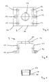
- Figur 1:
- Ein Türblatt im Querschnitt, das einseitig einen erfindungsgemäßen Beschlag mit Zutrittskontrollsystem aufweist.
- Figur 2:
- Eine Draufsicht auf den erfindungsgemäßen Beschlag ohne Beschlagoberteil.
- Figur 3:
- Eine Seitenansicht des Türblattes gemäß Figur 1.
- Figur 4:
- Einen Bügel zur Befestigung des Zutrittkontrollsystemes in einer Draufsicht.
- Figur 5:
- Den Bügel gemäß Figur 4 in einer Seitenansicht.
- Figur 6:
- Eine Hülse mit einem Außengewinde und einem Rand.
- 1
- Türblatt
- 2
- Beschlag
- 3
- Beschlag
- 4
- Schließmechanismus
- 5
- Zutrittskontrollsystem
- 6
- Drücker
- 7
- Beschlagunterteil
- 8
- Beschlagoberteil
- 9
- Bügel
- 10
- Basisteil
- 11
- Schenkel
- 12
- Lasche
- 13
- Bohrung
- 14
- Schraube
- 15
- Gewindebohrung
- 16
- Bohrung
- 17
- Hülse
- 18
- Außengewinde
- 19
- Rand
Claims (8)
- Beschlag bestehend aus einem Beschlagoberteil (8) und aus einem Beschlagunterteil (7), wobei das Beschlagunterteil (7) fest mit einem Türblatt (1) verbunden ist und wobei zwischen dem Beschlagunterteil (7) und dem Beschlagoberteil (8) ein Zutrittskontrollsystem (5) adaptiv angeordnet ist, dadurch gekennzeichnet, dass das Zutrittskontrollsystem (5) mit einem Bügel (9) an dem Beschlagunterteil (7) befestigt ist.
- Beschlag nach Anspruch 1, dadurch gekennzeichnet, dass der Bügel (9) U-förmig ausgeführt ist und mit dem Zutrittskontrollsystem (5) und mit dem Beschlagunterteil (7) verschraubt ist.
- Beschlag nach einem der vorhergehenden Ansprüche, dadurch gekennzeichnet, dass der Bügel (9) aus einem Basisteil (10) besteht, von dem Schenkel (11) parallel abgebogen sind, die an ihren freien Enden auswärts abgebogene Laschen (12) aufweisen.
- Beschlag nach einem der vorhergehenden Ansprüche, dadurch gekennzeichnet, dass die Schenkel (11) und die Laschen (12) gesenkte Bohrungen (13) aufweisen.
- Beschlag nach einem der vorhergehenden Ansprüche, dadurch gekennzeichnet, dass der Bügel (9) in dem Basisteil (10) eine Gewindebohrung (15) aufweist.
- Beschlag nach einem der vorhergehenden Ansprüche, dadurch gekennzeichnet, dass eine Hülse (17) ein Außengewinde (18) und einen umlaufenden Rand (19) aufweist, wobei die Hülse (17) durch eine Bohrung (16) des Beschlagoberteiles (8) in die Gewindebohrung (15) des Basisteiles (10) des Bügels (9) einschraubbar ist.
- Beschlag nach einem der vorhergehenden Ansprüche, dadurch gekennzeichnet, dass der Beschlag (3) an Türblättern (1) aus Glas angeordnet ist.
- Beschlag nach einem der vorhergehenden Ansprüche, dadurch gekennzeichnet, dass sowohl dem Beschlagunterteil (7) als auch dem Schließmechanismus (4) je ein Zutrittskontrollsystem (5) zugeordnet ist.
Applications Claiming Priority (2)
| Application Number | Priority Date | Filing Date | Title |
|---|---|---|---|
| DE20316298U | 2003-10-21 | ||
| DE20316298U DE20316298U1 (de) | 2003-10-21 | 2003-10-21 | Beschlag |
Publications (2)
| Publication Number | Publication Date |
|---|---|
| EP1526231A2 true EP1526231A2 (de) | 2005-04-27 |
| EP1526231A3 EP1526231A3 (de) | 2006-02-01 |
Family
ID=29796964
Family Applications (1)
| Application Number | Title | Priority Date | Filing Date |
|---|---|---|---|
| EP04024996A Withdrawn EP1526231A3 (de) | 2003-10-21 | 2004-10-20 | Beschlag |
Country Status (2)
| Country | Link |
|---|---|
| EP (1) | EP1526231A3 (de) |
| DE (1) | DE20316298U1 (de) |
Family Cites Families (6)
| Publication number | Priority date | Publication date | Assignee | Title |
|---|---|---|---|---|
| US5083122A (en) * | 1989-02-21 | 1992-01-21 | Osi Security Devices | Programmable individualized security system for door locks |
| IT1238550B (it) * | 1990-04-11 | 1993-08-18 | Italiana Serrature Affini | Dispositivo per l'azionamento dello scrocco in serrature con funzionamento a scheda magnetica. |
| US5475996A (en) * | 1994-08-29 | 1995-12-19 | Chen; Tsun-Hsing | Electromagnetic door lock |
| US6244084B1 (en) * | 1998-02-27 | 2001-06-12 | Tod L. Warmack | Remote control lock device |
| US5974912A (en) * | 1998-11-13 | 1999-11-02 | Cheng; Tung-Chi | Door lock unlockable electro-magnetically and with a key |
| CA2331512C (en) * | 2000-01-19 | 2009-04-07 | Schlage Lock Company | Interconnected lock with remote unlocking mechanism |
-
2003
- 2003-10-21 DE DE20316298U patent/DE20316298U1/de not_active Expired - Lifetime
-
2004
- 2004-10-20 EP EP04024996A patent/EP1526231A3/de not_active Withdrawn
Also Published As
| Publication number | Publication date |
|---|---|
| EP1526231A3 (de) | 2006-02-01 |
| DE20316298U1 (de) | 2003-12-18 |
Similar Documents
| Publication | Publication Date | Title |
|---|---|---|
| DE102007046538A1 (de) | Griffbefestigung und Beschlag mit Griffbefestigung | |
| EP2796645A2 (de) | Riegelschloss eines Möbels | |
| EP0215281B1 (de) | Flügellager für ein Fenster, eine Tür od. dgl. | |
| EP0458777B1 (de) | Zylinderschloss | |
| EP2113624A2 (de) | Tür- oder Fenstersicherungsvorrichtung | |
| DE19540505A1 (de) | Türschließer mit selbsttätiger Schließbewegung und verdeckt angeordnetem Schließergehäuse | |
| DE202020100649U1 (de) | Profilierter Spindel-Einsatz für Türschlösser | |
| DE102008036151A1 (de) | Scharnierband mit einer Unterkonstruktion zur Befestigung an einem Türblatt | |
| EP1918492A2 (de) | Beschlag für die Befestigung eines Drückers an einer Tür oder einem Fester | |
| EP2304148B1 (de) | Bandsystem | |
| EP3029227B2 (de) | Beschlag mit einstellbarem Einspannbereich | |
| DE20316298U1 (de) | Beschlag | |
| EP0930410B1 (de) | Betätigungshandhabe | |
| EP0036480A1 (de) | Ganzglasflügel-Beschlag | |
| DE9414208U1 (de) | Beschlagunterteil | |
| WO2004113653A1 (de) | Notentriegelungsvorrichtung | |
| DE102014222886B4 (de) | System zur Befestigung eines obenliegenden Türschließers | |
| EP1813754B1 (de) | Obertürschliesser | |
| DE29702743U1 (de) | Schutzbeschlag zur Sicherung des Schloßgesperres einer Tür | |
| EP1498563B1 (de) | Spaltlüftungsvorrichtung | |
| DE202007011394U1 (de) | Fenster oder Tür und Bauteilsatz eines Riegelteils für ein Fenster oder eine Tür | |
| DE102009023130B4 (de) | Beschlag für Fenster, Türen oder Tore | |
| DE202022102064U1 (de) | Sperrvorrichtung für Fensterbeschläge | |
| DE10163740B4 (de) | Fensterrahmen oder Türblatt mit einer Betätigungshandhabe | |
| EP3211160B1 (de) | Rosette |
Legal Events
| Date | Code | Title | Description |
|---|---|---|---|
| PUAI | Public reference made under article 153(3) epc to a published international application that has entered the european phase |
Free format text: ORIGINAL CODE: 0009012 |
|
| AK | Designated contracting states |
Kind code of ref document: A2 Designated state(s): AT BE BG CH CY CZ DE DK EE ES FI FR GB GR HU IE IT LI LU MC NL PL PT RO SE SI SK TR |
|
| AX | Request for extension of the european patent |
Extension state: AL HR LT LV MK |
|
| PUAL | Search report despatched |
Free format text: ORIGINAL CODE: 0009013 |
|
| AK | Designated contracting states |
Kind code of ref document: A3 Designated state(s): AT BE BG CH CY CZ DE DK EE ES FI FR GB GR HU IE IT LI LU MC NL PL PT RO SE SI SK TR |
|
| AX | Request for extension of the european patent |
Extension state: AL HR LT LV MK |
|
| STAA | Information on the status of an ep patent application or granted ep patent |
Free format text: STATUS: THE APPLICATION HAS BEEN WITHDRAWN |
|
| 18W | Application withdrawn |
Effective date: 20060725 |