EP1526036B1 - Tipping device for a tipping load vehicle - Google Patents
Tipping device for a tipping load vehicle Download PDFInfo
- Publication number
- EP1526036B1 EP1526036B1 EP04022566A EP04022566A EP1526036B1 EP 1526036 B1 EP1526036 B1 EP 1526036B1 EP 04022566 A EP04022566 A EP 04022566A EP 04022566 A EP04022566 A EP 04022566A EP 1526036 B1 EP1526036 B1 EP 1526036B1
- Authority
- EP
- European Patent Office
- Prior art keywords
- cylinder
- tipping
- hydraulic
- piston
- pressure
- Prior art date
- Legal status (The legal status is an assumption and is not a legal conclusion. Google has not performed a legal analysis and makes no representation as to the accuracy of the status listed.)
- Active
Links
Images


Classifications
-
- B—PERFORMING OPERATIONS; TRANSPORTING
- B60—VEHICLES IN GENERAL
- B60P—VEHICLES ADAPTED FOR LOAD TRANSPORTATION OR TO TRANSPORT, TO CARRY, OR TO COMPRISE SPECIAL LOADS OR OBJECTS
- B60P1/00—Vehicles predominantly for transporting loads and modified to facilitate loading, consolidating the load, or unloading
- B60P1/04—Vehicles predominantly for transporting loads and modified to facilitate loading, consolidating the load, or unloading with a tipping movement of load-transporting element
- B60P1/26—Means for controlling movement of tailboards or sideboards
- B60P1/273—Providing interdependence between tipping movement and the latching or unlatching of a freely-swingable tailboard or sideboard
Definitions
- the invention relates to a tilting device of a dump truck, with a tilting structure and a hydraulic tilting drive device for pivoting the tilting structure about a normally horizontal tilting axis, the tilting structure comprising a frame and at least one side wall flap, in particular a rear wall flap, pivotable about a pivot axis for closing and opening a discharge area of the tilting structure and further comprising a locking device locking the side wall flap in its closed position, wherein at least one hydraulic cylinder-piston unit is provided as the pivoting drive device for the side wall flap, by means of which the locking device can also be actuated in order to release the side wall flap from its lock, wherein the cylinder Piston unit via a control valve assembly with pressure from a one of the side wall flap actuator associated hydraulic circuit is acted upon to the opening movement of the side wall flap causing piston stroke of the cylinder-piston unit to produce.
- a tilting device of the aforementioned type is for example from the DE 199 40 811 A1 known.
- the aim of the invention is to provide in such a tilting device with simple means that the process of unlocking the side wall flap, especially when initiating a tilting of the tipper body can run reliably and trouble-free.
- the Bordwandklappenbetutzson associated hydraulic circuit is usually dimensioned in the tilting devices of the type mentioned that he can provide the cylinder-piston unit with a sufficient for the pivoting of the side wall flap and under normal conditions for unlocking the side wall flap pressure.
- two similar cylinder-piston units are provided for the side wall flap operation on the opposite sides of the tilting structure between the Kipp initiatedrahmen and swivel brackets of the side wall flap.
- the cylinder-piston units should be as small as possible. However, this requires that they can normally only be operated with limited hydraulic pressure. It has been shown in the past in conventional tilting devices of the type considered here that the hydraulic cylinder-piston units did not reliably unlock the side wall flap in all load situations.
- a new way is shown, such as a reliable unlocking the side wall flap even under extreme Loading conditions of the flap can be ensured without having to over-dimension the cylinder-piston units beyond the normal requirement profile corresponding measure.
- the solution consists in providing pressure from the auxiliary hydraulic circuit essentially only for the unlocking process of the side wall flap. Since the unlocking operation is already completed after the piston of the cylinder-piston unit has performed a comparatively small limited initial piston stroke, the pressurization of the hydraulic cylinder-piston unit with the increased pressure of the auxiliary circuit normally takes place only for a short time and only during the initial Range of the piston stroke. Such a security solution can be realized with little effort.
- the tilting device comprises control means which are adapted to automatically activate the auxiliary hydraulic circuit for acting on the cylinder-piston unit with the initiation of tilting of the tilting structure out of the basic driving position.
- the locking device has at least one on Kipp initiatedrahmen near the Aus frequently Scheme Schemees fastened locking element, which engages behind a locking counter-element of the side wall flap in its closed position locking, wherein the lock by lifting the side wall flap is releasable.
- the side wall flap is attached in the vicinity of its in the closed position upper end to a swivel mounting arrangement, which is pivotable from a corresponding with the closed position of the side wall flap position by means of the cylinder-piston unit about the pivot axis to the side wall flap from its closed position by lifting to unlock and to pivot in an open position.
- the cylinder-piston unit in an unlocking mode is so controlled that it essentially only executes the limited to unlock the side wall flap piston stroke, the thus unlocked side panel flap on the pivot bracket assembly can oscillate about an axis parallel to the tilt axis when the tipping assembly is pivoted in a raised tilted position.
- the tailgate flap will tend to assume its vertically oriented position during the pendulum action due to its gravity.
- the swinging side wall can have a metering effect on the unloading because it does not completely release the discharge area. From such a dosing effect is e.g. Use made when a dump truck is operated in combination with a paver when applying a road surface, with a continuous flow of the load of the dump truck from the tipping position brought into tipping is to take place in a hopper of the tipper vehicle following paver.
- the hydraulic auxiliary circuit is connected to the pressure side of a pump for the hydraulic supply of the tilting drive device.
- the auxiliary circuit is thus branched off from the hydraulic circuit for operating the tilting drive device, that is to say for supplying a possibly telescopic tilting cylinder.
- the Hydraulic circuit of the tilt drive device is dimensioned so that a sufficiently high pressure for the unlocking process of the side wall flap can be diverted via the hydraulic auxiliary circuit.
- the pressure fluid sources of the auxiliary hydraulic circuit and the hydraulic main circuit for the side wall flap operation may include various pumps or possibly go back to a common pump.
- a preferably hydraulically translating pressure transfer cylinder is included.
- this pressure-transmitting cylinder has the function of limiting the quantity of pressurized fluid provided by the hydraulic auxiliary circuit for the unlocking process of the side wall flap to a predetermined value.
- this pressure transfer cylinder has a large hydraulic ratio, so that in this way a sufficiently high pressure for the unlocking operation on the hydraulic cylinder-piston unit can be generated.
- a piston rod having a piston in two cylinder chambers, wherein the penetrated by the piston rod cylinder chamber hydraulically with the cylinder-piston unit for unlocking and for the pivot drive of the side wall flap in conjunction whereas the other cylinder chamber is possibly connected via a valve arrangement to a pressure fluid pump, wherein the pressure transfer cylinder is dimensioned such that the pressure fluid quantity displaced by it at the complete maximum stroke of its piston to the cylinder-piston unit is sufficient to reach the cylinder Piston unit to cause a limited essentially to the unlocking operation of the locking device piston stroke. Because of the piston rod, the piston has differently sized axially loaded surfaces on the border with the cylinder chambers, so that it can translate hydraulically.
- the piston rod of the pressure booster cylinder is always returned to the retracted home position when the tilting structure is pivoted out of its tilted position back into its lowered driving operation basic position.
- the pressure transfer cylinder is fixed to a vehicle frame part or stationary, that it can be mechanically engaged by the tipper body to transfer the piston rod to the retracted home position in the pressure transfer cylinder when the tipping body transitions from its raised tilting position into the basic driving position.
- a rear wall flap 4 attached to Schwenkhalterungsarmen 6 hanging in the manner explained in more detail below.
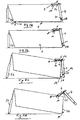
- the Schwenkhalterungsarme 6 are about an indicated at 8 axis between the in Fig. 1 with solid lines shown first position, which corresponds to the closed position of the side wall flap 4, and a in Fig. 1 pivoted with broken lines shown second position.
- hydraulic cylinder-piston units 10 are provided, which are mounted with its cylinder end in the upper region of the side wall 12 inside of Kipp incompleterahmen - and with its piston rod end to the Schwenkhalterungsarmen 6.
- the side wall flap 4 closes in its closed position the rear-side discharge area 14 of the tilting structure 2.
- the closed position of the side wall flap 4 is also in the simplified representation according to Fig. 2a to recognize.
- Fig. 2a-2d Furthermore, it can be seen that the side wall flap 4 is articulated on the pivot support arm protruding to the rear from the pivot axis 8 in such a way that, by pivoting the pivot support arm 6, it can lift (see the change between FIG Fig. 2a and 2b ), in which the locking counter-element 20 of the side wall flap 4 of the locking element 18 is released. If the pivoting process of the Schwenkhalterungsarme 6 stopped in this state of the side wall flap 4, the unlocked side wall flap 4 about the pendulum axis 22 (see. Fig. 2c ) oscillate when the tilting structure is tilted about the tilting axis 19, wherein the in Fig. 2c shown vertical position is strived for and possibly prevented by bulk material, which flows in the discharge area 14 of the tipper body 2.
- Fig. 3 a simplified hydraulic circuit diagram is shown, based on which the unlocking and pivoting operation of the side wall flap 4 will be explained in more detail below.
- Fig. 3 the double-acting hydraulic cylinder-piston units for the operation of the side wall flap 4 characterized. They are connected via hydraulic lines 30, 32 to a control valve block 34 for controlling the pressure fluid flow from the pump 36 to the cylinders 10 and for controlling the pressure fluid discharge from the cylinders 10 to a tank 60.
- the valve setting of the control valve block 34 by means of a (not shown) pneumatic adjusting device in accordance with the operation of an example provided in a cab of the dump truck operating device, such as a shift lever.
- a (not shown) pneumatic adjusting device in accordance with the operation of an example provided in a cab of the dump truck operating device, such as a shift lever.
- the single-acting Tilting cylinder 23 is connected via the hydraulic line 38 to the tilting valve block 40 for controlling the pressure fluid flow from the pump 42 to the tilting cylinder 23 and for controlling the return flow from the tilting cylinder 23 to the tank 60.
- a pressure transmission cylinder 46 is provided, the cylinder space is divided by a piston 48 into two cylinder chambers 50, 52.
- the connected to the hydraulic line 30 cylinder chamber 52 is penetrated by the piston rod 49 of the piston 48.
- the rodless cylinder chamber 50 is connected to the pressure fluid line 38.
- the pressure transfer cylinder 46 is a hydraulic transmission element, which comes into effect when the piston 48 performs a piston stroke when pressurized in the cylinder chamber 50. He transmits the high pressure to the hydraulic fluid line 30 and thus to the in Fig.
- the hydraulic auxiliary circuit comprises in the example, the pump 42, the branch line 44 with the pressure transfer cylinder 46 provided therein and a return path 70 to the tank, said return path includes a normally-off control valve 72 which is controlled by the pressure in the line 30, such that at Pressure supply to the cylinder chambers 54 of the cylinder-piston units 10, the control valve 72 is switched to passage to the tank 60. It can then pass through the lines 32 and 70 displaced from the cylinder chambers 61 hydraulic fluid to the tank 60.
- the hydraulic fluid used is preferably oil.
- FIG. 4 shows a simplified hydraulic circuit diagram for a further embodiment of the invention. As far as in Fig. 4 functionally or objectively the same elements as in Fig. 3 are shown, these elements are in both FIGS. 3 and 4 each marked with the same reference numerals.
- the pressure transfer cylinder 46 is in Fig. 4 supplied by the pump 36, which is responsible for the pivoting operation of the cylinder-piston units 10. According to the embodiment Fig. 4 It is necessary that the pressure transfer cylinder 46 has the largest possible hydraulic translation to produce sufficiently large piston rod forces on the cylinder-piston units 10.
- control valve block 34 and the pump 36 are still a control valve 74 for controlling the pressure fluid flow from the pump 36 to the pressure transfer cylinder 46 and 46 provided by the pressure transfer cylinder back to the tank 60.
Abstract
Description
Die Erfindung betrifft eine Kippvorrichtung eines Kipperfahrzeugs, mit einem Kippaufbau und einer hydraulischen Kippantriebseinrichtung zum Schwenken des Kippaufbaus um eine normalerweise horizontale Kippachse, wobei der Kippaufbau einen Rahmen und daran wenigstens eine zum Schließen und Öffnen eines Ausschüttbereiches des Kippaufbaus um eine Schwenkachse schwenkbare Bordwandklappe, insbesondere Heckwandklappe, und ferner eine die Bordwandklappe in deren Schließstellung verriegelnde Verriegelungseinrichtung aufweist, wobei als Schwenkantriebsvorrichtung für die Bordwandklappe wenigstens eine hydraulische Zylinder-Kolben-Einheit vorgesehen ist, mittels derer auch die Verriegelungseinrichtung betätigbar ist, um die Bordwandklappe aus ihrer Verriegelung freizugeben, wobei die Zylinder-Kolben-Einheit über eine Steuerventilanordnung mit Druck aus einem einem der Bordwandklappenbetätigung zugeordneten hydraulischen Kreis beaufschlagbar ist, um einen die Öffnungsbewegung der Bordwandklappe auslösenden Kolbenhub der Zylinder-Kolben-Einheit zu erzeugen.The invention relates to a tilting device of a dump truck, with a tilting structure and a hydraulic tilting drive device for pivoting the tilting structure about a normally horizontal tilting axis, the tilting structure comprising a frame and at least one side wall flap, in particular a rear wall flap, pivotable about a pivot axis for closing and opening a discharge area of the tilting structure and further comprising a locking device locking the side wall flap in its closed position, wherein at least one hydraulic cylinder-piston unit is provided as the pivoting drive device for the side wall flap, by means of which the locking device can also be actuated in order to release the side wall flap from its lock, wherein the cylinder Piston unit via a control valve assembly with pressure from a one of the side wall flap actuator associated hydraulic circuit is acted upon to the opening movement of the side wall flap causing piston stroke of the cylinder-piston unit to produce.
Eine Kippvorrichtung der vorstehend genannten Art ist z.B. aus der
Ziel der Erfindung ist es, bei einer solchen Kippvorrichtung mit einfachen Mitteln dafür zu sorgen, dass der Vorgang der Entriegelung der Bordwandklappe, insbesondere bei Einleitung eines Kippvorgangs des Kippaufbaus zuverlässig und störungsfrei ablaufen kann.The aim of the invention is to provide in such a tilting device with simple means that the process of unlocking the side wall flap, especially when initiating a tilting of the tipper body can run reliably and trouble-free.
Zur Lösung dieser Aufgabe wird ausgehend von einer Kippvorrichtung der eingangs genannten Art erfindungsgemäß vorgeschlagen, dass die Zylinder-Kolben-Einheit über einen zumindest dem Entriegelungsvorgang der Verriegelungseinrichtung entsprechenden begrenzten Bereich ihres Kolbenhubs mit einem erhöhten Druck aus einem hydraulischen Hilfskreis beaufschlagbar ist.To solve this problem is proposed according to the invention, starting from a tilting device of the type mentioned, that the cylinder-piston unit via an at least the unlocking of the locking device corresponding limited range of their piston stroke can be acted upon by an increased pressure from a hydraulic auxiliary circuit.
Der der Bordwandklappenbetätigung zugeordnete hydraulische Kreis ist bei den Kippvorrichtungen der eingangs genannten Art normalerweise so dimensioniert, dass er die Zylinder-Kolben-Einheit mit einem für das Verschwenken der Bordwandklappe und unter Normalbedingungen auch für das Entriegeln der Bordwandklappe hinreichend hohen Druck versorgen kann. Üblicherweise sind zwei gleichartige Zylinder-Kolben-Einheiten für die Bordwandklappenbetätigung an den einander gegenüberliegenden Seiten des Kippaufbaus zwischen dem Kippaufbaurahmen und Schwenkhalterungen der Bordwandklappe vorgesehen. Aus Platzgründen sollten die Zylinder-Kolben-Einheiten möglichst klein sein. Dies bedingt jedoch, dass sie normalerweise nur mit begrenztem hydraulischem Druck betrieben werden können. Es hat sich in der Vergangenheit bei konventionellen Kippvorrichtungen der hier betrachteten Art gezeigt, dass die hydraulischen Zylinder-Kolben-Einheiten die Bordwandklappe nicht in allen Belastungssituationen zuverlässig entriegelten. Eine solche Belastungssituation kann gegeben sein, wenn der Kippaufbau mit schwerem Schüttgut beladen ist und die Ladung so auf die Bordwandklappe drückt, dass die Verriegelungselemente der Verriegelungseinrichtung aneinander klemmen. Bisherige Versuche, dieses Problem zu überwinden, liefen darauf hinaus, größer dimensionierte Zylinder-Kolben-Einheiten zu verwenden und in entsprechender Weise auch den Hydraulikkreis für die Bordwandklappenbetätigung stärker zu dimensionieren. Derartige Maßnahmen sind jedoch kontraproduktiv im Hinblick auf das Ziel, möglichst platzsparende und somit kleine Zylinder-Kolben-Einheiten und möglichst preiswerte Hydraulikkomponenten zu deren Betrieb vorzusehen.The Bordwandklappenbetätigung associated hydraulic circuit is usually dimensioned in the tilting devices of the type mentioned that he can provide the cylinder-piston unit with a sufficient for the pivoting of the side wall flap and under normal conditions for unlocking the side wall flap pressure. Usually two similar cylinder-piston units are provided for the side wall flap operation on the opposite sides of the tilting structure between the Kippaufbaurahmen and swivel brackets of the side wall flap. For space reasons, the cylinder-piston units should be as small as possible. However, this requires that they can normally only be operated with limited hydraulic pressure. It has been shown in the past in conventional tilting devices of the type considered here that the hydraulic cylinder-piston units did not reliably unlock the side wall flap in all load situations. Such a loading situation may be present when the tipper body is loaded with heavy bulk material and the cargo presses on the side wall flap, that the locking elements of the locking device clamp together. Previous attempts to overcome this problem have resulted in using larger sized cylinder-piston units and, in a corresponding manner, to increase the size of the hydraulic circuit for the tailgate operation. However, such measures are counterproductive in terms of the goal to provide space-saving and thus small cylinder-piston units and inexpensive hydraulic components as possible to their operation.
Gemäß der vorliegenden Erfindung wird jedoch ein neuer Weg aufgezeigt, wie eine zuverlässig Entriegelung der Bordwandklappe auch unter extremen Belastungszuständen der Klappe sichergestellt werden kann, ohne die Zylinder-Kolben-Einheiten über das ihrem normalen Anforderungsprofil entsprechende Maß hinaus wesentlich überdimensionieren zu müssen.According to the present invention, however, a new way is shown, such as a reliable unlocking the side wall flap even under extreme Loading conditions of the flap can be ensured without having to over-dimension the cylinder-piston units beyond the normal requirement profile corresponding measure.
Wie schon erwähnt, besteht der Lösungsansatz daran, im Wesentlichen nur für den Entriegelungsvorgang der Bordwandklappe Druck aus dem hydraulischen Hilfskreis bereitzustellen. Da der Entriegelungsvorgang bereits abgeschlossen ist, nachdem der Kolben der Zylinder-Kolben-Einheit einen vergleichsweise kleinen begrenzten anfänglichen Kolbenhub ausgeführt hat, erfolgt die Beaufschlagung der hydraulischen Zylinder-Kolben-Einheit mit dem erhöhten Druck des Hilfskreises normalerweise nur kurzzeitig und auch nur während des anfänglichen Bereichs des Kolbenhubs. Eine derartige Sicherheitslösung ist mit geringem Aufwand realisierbar.As already mentioned, the solution consists in providing pressure from the auxiliary hydraulic circuit essentially only for the unlocking process of the side wall flap. Since the unlocking operation is already completed after the piston of the cylinder-piston unit has performed a comparatively small limited initial piston stroke, the pressurization of the hydraulic cylinder-piston unit with the increased pressure of the auxiliary circuit normally takes place only for a short time and only during the initial Range of the piston stroke. Such a security solution can be realized with little effort.
Bei den hier betrachteten Kippvorrichtungen sollte sichergestellt sein, dass die Bordwandklappe entriegelt wird, wenn der beladene Kippaufbau in eine Kippstellung verschwenkt wird. Sollte die Bordwand dabei starr verriegelt bleiben, so könnte sich die Ladung, etwa Schüttgut, an der verschlossenen Bordwand stauen und somit eine gefährliche Gewichtsverlagerung des mit der Kippvorrichtung ausgerüsteten Kipperfahrzeugs herbeiführen.In the tilters considered here should be ensured that the side wall flap is unlocked when the loaded tipper body is pivoted to a tilted position. If the side wall remains rigidly locked, then the cargo, such as bulk goods, could accumulate on the closed side wall and thus bring about a dangerous shifting of the weight of the dump truck equipped with the tilting device.
Bei entriegelter Bordwand kann die Ladung beim Kippen des Kipperaufbaus normalerweise am Ausschüttbereich den Kippaufbau verlassen, so dass die vorstehend angesprochene gefährliche Situation einer kritischen Gewichtsverlagerung nicht eintreten sollte. Demgemäß wird vorgeschlagen, dass die Kippvorrichtung Steuerungsmittel aufweist, die dazu eingerichtet sind, mit dem Einleiten des Kippens des Kippaufbaus aus der Fahrbetriebsgrundstellung heraus automatisch den hydraulischen Hilfskreis zur Beaufschlagung der Zylinder-Kolben-Einheit zu aktivieren.When the side wall is unlocked, the load can normally leave the tipping body at the dumping area when tilting the tipper body, so that the above-mentioned dangerous situation of critical weight shifting should not occur. Accordingly, it is proposed that the tilting device comprises control means which are adapted to automatically activate the auxiliary hydraulic circuit for acting on the cylinder-piston unit with the initiation of tilting of the tilting structure out of the basic driving position.
Gemäß einer bevorzugten Ausführungsform der Erfindung weist die Verriegelungseinrichtung wenigstens ein am Kippaufbaurahmen in der Nähe des Ausschüttbereiches befestigtes Verriegelungselement auf, welches ein Verriegelungsgegenelement der Bordwandklappe in deren Schließstellung verriegelnd hintergreift, wobei die Verriegelung durch Anheben der Bordwandklappe lösbar ist. Die Bordwandklappe ist in der Nähe ihres in der Schließstellung oberen Endes an einer Schwenkhalterungsanordnung angehängt, welche ausgehend von einer mit der Schließstellung der Bordwandklappe korrespondierenden Stellung mittels der Zylinder-Kolben-Einheit um die Schwenkachse schwenkbar ist, um die Bordwandklappe aus ihrer Schließstellung heraus durch Anheben zu entriegeln und in eine Öffnungsstellung zu verschwenken.According to a preferred embodiment of the invention, the locking device has at least one on Kippaufbaurahmen near the Ausschüttbereiches fastened locking element, which engages behind a locking counter-element of the side wall flap in its closed position locking, wherein the lock by lifting the side wall flap is releasable. The side wall flap is attached in the vicinity of its in the closed position upper end to a swivel mounting arrangement, which is pivotable from a corresponding with the closed position of the side wall flap position by means of the cylinder-piston unit about the pivot axis to the side wall flap from its closed position by lifting to unlock and to pivot in an open position.
Vorzugsweise ist die Zylinder-Kolben-Einheit in einer Entriegelungsbetriebsart so ansteuerbar, dass sie im Wesentlichen nur den zur Entriegelung der Bordwandklappe begrenzten Kolbenhub ausführt, wobei die auf diese Weise entriegelte Bordwandklappe an der Schwenkhalterungsanordnung um eine zur Kippachse parallele Achse pendeln kann, wenn der Kippaufbau in eine angehobene Kippstellung verschwenkt wird. Die Bordwandklappe wird bei dem Pendelvorgang aufgrund ihrer Schwerkraft zur Einnahme ihrer vertikal ausgerichteten Stellung tendieren. Beim Entladen von Schüttgut kann die pendelnde Bordwand einen dosierenden Effekt auf das Entladen haben, da sie den Ausschüttbereich nicht völlig freigibt. Von einem solchen Dosiereffekt wird z.B. Gebrauch gemacht, wenn ein Kipperfahrzeug in Kombination mit einem Straßenfertiger beim Aufbringen eines Straßenbelages betrieben wird, wobei ein kontinuierlicher Fluss des Ladegutes des Kipperfahrzeugs aus dem in Kippstellung gebrachten Kippaufbau in einen Trichter des dem Kipperfahrzeug folgenden Straßenfertigers erfolgen soll.Preferably, the cylinder-piston unit in an unlocking mode is so controlled that it essentially only executes the limited to unlock the side wall flap piston stroke, the thus unlocked side panel flap on the pivot bracket assembly can oscillate about an axis parallel to the tilt axis when the tipping assembly is pivoted in a raised tilted position. The tailgate flap will tend to assume its vertically oriented position during the pendulum action due to its gravity. When unloading bulk material, the swinging side wall can have a metering effect on the unloading because it does not completely release the discharge area. From such a dosing effect is e.g. Use made when a dump truck is operated in combination with a paver when applying a road surface, with a continuous flow of the load of the dump truck from the tipping position brought into tipping is to take place in a hopper of the tipper vehicle following paver.
Gemäß einer bevorzugten Weiterbildung der Erfindung ist der hydraulische Hilfskreis an der Druckseite einer Pumpe zur hydraulischen Versorgung der Kippantriebsvorrichtung angeschlossen. Der Hilfskreis ist somit von dem hydraulischen Kreis zum Betrieb der Kippantriebseinrichtung, also etwa zur Versorgung eines ggf. teleskopierbaren Kippzylinders abgezweigt. Der Hydraulikkreis der Kippantriebseinrichtung ist so dimensioniert, dass über den hydraulischen Hilfskreis ein hinreichend hoher Druck für den Entriegelungsvorgang der Bordwandklappe abgezweigt werden kann.According to a preferred embodiment of the invention, the hydraulic auxiliary circuit is connected to the pressure side of a pump for the hydraulic supply of the tilting drive device. The auxiliary circuit is thus branched off from the hydraulic circuit for operating the tilting drive device, that is to say for supplying a possibly telescopic tilting cylinder. Of the Hydraulic circuit of the tilt drive device is dimensioned so that a sufficiently high pressure for the unlocking process of the side wall flap can be diverted via the hydraulic auxiliary circuit.
In Ausführungsvarianten der Erfindung können die Druckfluidquellen des hydraulischen Hilfskreises und des hydraulischen Hauptkreises für die Bordwandklappenbetätigung verschiedene Pumpen umfassen oder ggf. auf eine gemeinsame Pumpe zurückgehen.In embodiments of the invention, the pressure fluid sources of the auxiliary hydraulic circuit and the hydraulic main circuit for the side wall flap operation may include various pumps or possibly go back to a common pump.
In dem hydraulischen Hilfskreis ist gemäß einer besonders bevorzugten Ausführungsform der Erfindung ein vorzugsweise hydraulisch übersetzender Druckübertragungszylinder enthalten. Dieser Druckübertragungszylinder hat insbesondere die Funktion, die aus dem hydraulischen Hilfskreis für den Entriegelungsvorgang der Bordwandklappe bereitgestellte Druckfluidmenge auf einen vorbestimmten Wert zu begrenzen. Vorzugsweise hat dieser Druckübertragungszylinder eine große hydraulische Übersetzung, so dass auch auf diese Weise ein für den Entriegelungsvorgang ausreichend hoher Druck an der hydraulischen Zylinder-Kolben-Einheit erzeugt werden kann. Gemäß einer Variante der Ausführungsform der Erfindung mit Druckübertragungszylinder ist dieser innen von einem einseitig eine Kolbenstange aufweisenden Kolben in zwei Zylinderkammern unterteilt, wobei die von der Kolbenstange durchsetzte Zylinderkammer hydraulisch mit der Zylinder-Kolben-Einheit für die Entriegelung und für den Schwenkantrieb der Bordwandklappe in Verbindung steht, wohingegen die andere Zylinderkammer ggf. über eine Ventilanordnung an einer Druckfluid fördernden Pumpe angeschlossen ist, wobei der Druckübertragungszylinder so dimensioniert ist, dass die von ihm bei vollständigem Maximalhub seines Kolbens zu der Zylinder-Kolben-Einheit verdrängte Druckfluidmenge ausreicht, um bei der Zylinder-Kolben-Einheit einen im Wesentlichen auf den Entriegelungsvorgang der Verriegelungseinrichtung begrenzten Kolbenhub zu verursachen. Der Kolben hat wegen der Kolbenstange unterschiedlich große axial beaufschlagte Flächen an der Grenze zu den Zylinderkammern, so dass er hydraulisch übersetzen kann.In the auxiliary hydraulic circuit according to a particularly preferred embodiment of the invention, a preferably hydraulically translating pressure transfer cylinder is included. In particular, this pressure-transmitting cylinder has the function of limiting the quantity of pressurized fluid provided by the hydraulic auxiliary circuit for the unlocking process of the side wall flap to a predetermined value. Preferably, this pressure transfer cylinder has a large hydraulic ratio, so that in this way a sufficiently high pressure for the unlocking operation on the hydraulic cylinder-piston unit can be generated. According to a variant of the embodiment of the invention with pressure transmission cylinder of this is divided on the one hand a piston rod having a piston in two cylinder chambers, wherein the penetrated by the piston rod cylinder chamber hydraulically with the cylinder-piston unit for unlocking and for the pivot drive of the side wall flap in conjunction whereas the other cylinder chamber is possibly connected via a valve arrangement to a pressure fluid pump, wherein the pressure transfer cylinder is dimensioned such that the pressure fluid quantity displaced by it at the complete maximum stroke of its piston to the cylinder-piston unit is sufficient to reach the cylinder Piston unit to cause a limited essentially to the unlocking operation of the locking device piston stroke. Because of the piston rod, the piston has differently sized axially loaded surfaces on the border with the cylinder chambers, so that it can translate hydraulically.
Zwar sollte bei einer Ausführungsform der Kippvorrichtung nach der Erfindung mit hydraulischen Mitteln dafür gesorgt sein, dass die Kolbenstange des Druckübersetzungszylinders stets in die eingezogene Grundstellung zurückgeführt wird, wenn der Kippaufbau aus seiner Kippstellung heraus wieder in seine abgesenkte Fahrbetriebsgrundstellung verschwenkt wird. Als zusätzliche Sicherungsmaßnahme kann es im Rahmen der Erfindung vorgesehen sein, dass der Druckübertragungszylinder so an einem Fahrzeugrahmenteil oder dazu ortsfest angeordnet ist, dass er mechanisch von dem Kippaufbau in Eingriff genommen werden kann, um die Kolbenstange in die eingezogene Grundstellung im Druckübertragungszylinder zu überführen, wenn der Kippaufbau aus seiner angehobenen Kippstellung in die Fahrbetriebsgrundstellung übergeht.Although it should be ensured in one embodiment of the tilting device according to the invention with hydraulic means that the piston rod of the pressure booster cylinder is always returned to the retracted home position when the tilting structure is pivoted out of its tilted position back into its lowered driving operation basic position. As an additional safeguard, it may be provided within the scope of the invention that the pressure transfer cylinder is fixed to a vehicle frame part or stationary, that it can be mechanically engaged by the tipper body to transfer the piston rod to the retracted home position in the pressure transfer cylinder when the tipping body transitions from its raised tilting position into the basic driving position.
Die Erfindung wird anhand eines Ausführungsbeispiels unter Bezugnahme auf die Figuren näher erläutert.
- Fig. 1
- zeigt in einer Perspektivdarstellung den Heckbereich eines Kippaufbaus, bei dem es sich im Beispielsfall um eine als Kippmulde ausgebildete Kippbrücke handelt, wobei die Bordwand mit durchgezogenen Linien in der Schließstellung gezeigt ist, wohingegen mit unterbrochenen Linien angedeutet ist, wie die Bordwandklappe in ihrer Stellung maximaler Öffnung des Ausschüttbereichs des Kippaufbaus orientiert ist.
- Fig. 2a-2d
- zeigen in stark vereinfachten schematischen Darstellungen einen Kippaufbau der in
Fig. 1 gezeigten Art mit verschiedenen Stellungen der Bordwandklappe. - Fig. 3
- zeigt ein stark vereinfachtes Hydraulik-Schaltbild zur Erläuterung der hydraulischen Betätigung der Bordwandklappe.
- Fig. 4
- zeigt ein stark vereinfachtes Hydraulikschaltbild eines im Vergleich mit
Fig. 3 abgewandelten Ausführungsbeispiels.
- Fig. 1
- shows a perspective view of the rear portion of a tipper body, which is in the example a dumping tipping bridge, the ship's side wall is shown by solid lines in the closed position, whereas indicated by broken lines, as the side wall flap in its position maximum opening the discharge area of the tilting structure is oriented.
- Fig. 2a-2d
- show in greatly simplified schematic representations a tilting structure of the
Fig. 1 shown type with different positions of the side wall flap. - Fig. 3
- shows a highly simplified hydraulic circuit diagram for explaining the hydraulic actuation of the side wall flap.
- Fig. 4
- shows a highly simplified hydraulic circuit diagram of a comparison with
Fig. 3 modified embodiment.
Bei dem als Kippmulde ausgebildeten Kippaufbau 2 in
Als Schwenkantriebsglieder sind hydraulische Zylinder-Kolben-Einheiten 10 vorgesehen, welche mit ihrem Zylinderende im oberen Bereich der Seitenwand 12 innen am Kippaufbaurahmen - und mit ihrem Kolbenstangenende an den Schwenkhalterungsarmen 6 gelenkig befestigt sind.As a pivot drive members hydraulic cylinder-
Die Bordwandklappe 4 verschließt in ihrer Schließstellung den heckseitigen Ausschüttbereich 14 des Kippaufbaus 2.The side wall flap 4 closes in its closed position the rear-
An dem diesen Ausschüttbereich 14 begrenzenden Rahmen 16 des Kippaufbaus 2 ist ein im Beispielsfall klauenförmiges Verriegelungselement 18 fixiert, welches in der gezeigten Weise ein Verriegelungsgegenelement 20 der in Schließstellung befindlichen Bordwandklappe 4 verriegelnd hintergreift. Die Bordwandklappe 4 ist somit gesichert, um den Ausschüttbereich 14 zuverlässig zu verschließen.At this
Die Schließstellung der Bordwandklappe 4 ist auch in der vereinfachten Darstellung gemäß
Bei einem weiteren Verschwenken der Schwenkhalterungsarme 6 - ausgehend von der Stellung gemäß
In
Mit 10 sind in
Die Ventileinstellung des Steuerventilblocks 34 erfolgt mittels einer (nicht gezeigten) pneumatischen Stelleinrichtung nach Maßgabe der Bedienung einer z.B. in einem Fahrerhaus des Kipperfahrzeugs vorgesehenen Bedieneinrichtung, etwa eines Schalthebels. Mit 23 ist in
Beim Starten des Kippvorgangs wird daher das von dem Kolben 48 aus der Zylinderkammer 52 des Druckübertragungszylinders 46 verdrängte Druckfluid ausreichen, um einen kleinen, begrenzten Kolbenhub der Kolben 58 der Zylinder-Kolben-Einheiten 10 zu verursachen. Dieser Kolbenhub reicht aus, um die Schwenkhalterungsarme 6 (vgl.
Soll die Bordwandklappe 4 dann in die Stellung gemäß
Beim Zurückschwenken der Schwenkhalterungsarme 6 von der Stellung gemäß
Mit dem Einziehen der Kolbenstangen der Kolben 58 der Zylinder-Kolben-Einheiten 10 werden die Schwenkhalterungsarme 6 wieder in die Ausgangsstellung gemäß
Den vorstehend genannten Erläuterungen ist somit zusammenfassend zu entnehmen, dass zur Bereitstellung des für den Entriegelungsvorgang erforderlichen Druckes Druckfluid aus dem hydraulischen Hilfskreis bzw. Hilfszweig 44 in dosierter Menge bereitgestellt wird und die weitere Schwenkbetätigung der Bordwandklappe 4 dann durch den Betrieb des hydraulischen Hauptkreises erfolgt, welcher die Pumpe 36, den Steuerventilblock 34, die betreffenden Druckfluidleitungen 30, 32 und den Tank 60 umfasst.The above explanations can thus be summarized that in order to provide the pressure required for the unlocking process pressure fluid from the auxiliary hydraulic circuit or auxiliary branch 44 is provided in metered quantity and the further pivoting operation the
Der hydraulische Hilfskreis umfasst im Beispielsfall die Pumpe 42, die Zweigleitung 44 mit dem darin vorgesehenen Druckübertragungszylinder 46 sowie einen Rückleitungsweg 70 zum Tank, wobei dieser Rückleitungsweg ein normalerweise sperrendes Stellventil 72 enthält, welches vom Druck in der Leitung 30 gesteuert wird, derart, dass bei Druckzufuhr zu den Zylinderkammern 54 der Zylinder-Kolben-Einheiten 10 das Stellventil 72 auf Durchlass zum Tank 60 geschaltet wird. Es kann dann durch die Leitungen 32 und 70 das aus den Zylinderkammern 61 verdrängte Hydraulikfluid zum Tank 60 gelangen.The hydraulic auxiliary circuit comprises in the example, the
Als Hydraulikfluid kommt vorzugsweise Öl zum Einsatz.The hydraulic fluid used is preferably oil.
Im Unterschied zu der Ausführungsform nach
Zwischen dem Steuerventilblock 34 und der Pumpe 36 ist noch ein Stellventil 74 zur Steuerung des Druckfluidflusses von der Pumpe 36 zu dem Druckübertragungszylinder 46 bzw. vom Druckübertragungszylinder 46 zurück zum Tank 60 vorgesehen.Between the
Claims (10)
- A tipping apparatus of a tipper vehicle, with a tipping body (2) and a hydraulic tipping-drive device (23) for pivoting the tipping body (2) about a tipping axis (19), wherein the tipping body (2) has a frame (16) and thereon at least one tailgate flap (4), in particular a rear wall flap, for closing and opening a discharge section (14) of the tipping body (2) and which is pivotable about a pivot axis (8), and it also has a locking device (18,20) for locking the tailgate flap (4) in its closed position, wherein at least one hydraulic cylinder-piston unit (10) is provided as the pivoting-drive device for the tailgate flap, by means of which hydraulic cylinder-piston unit the locking device (18,20) can also be actuated so as to release the tailgate flap (4) from its locked condition, wherein pressure from a hydraulic primary circuit associated with the actuation of the tailgate flap (4) can be applied to the cylinder-piston unit (10) via a control valve assembly (34) so as to bring about the piston stroke of the cylinder-piston unit (10) triggering the opening movement of the tailgate flap (4),
characterised in that increased pressure from a hydraulic secondary circuit or secondary branch (44) can be applied to the cylinder-piston unit (10) over a limited portion of its piston stroke corresponding at least to the release operation of the locking device (18,20). - A tipping apparatus according to Claim 1, characterised by control means which, with the onset of the tipping of the tipper body from the normal travel position, are set up to activate automatically the hydraulic second circuit or secondary branch (44) so as to actuate the cylinder-piston unit (10).
- A tipping apparatus according to Claim 1 or 2,
characterised in that the locking device (18,20) has at least one locking element (18) which is fastened to the tipping body frame (16) in the vicinity of the discharge section (14) and which engages behind a locking counterpart (20) of the tailgate flap (4) in its locking position, wherein the locking can be released by lifting the tailgate flap (4), and in that in the vicinity of its upper end in the closed position the tailgate flap (4) is attached to a pivot mounting assembly (6), wherein, starting from a position corresponding to the closed position of the tailgate flap (4), the pivot mounting assembly (6) can be pivoted by means of the cylinder-piston unit (10) about the pivot axis (8) so to release the tailgate flap (4) from its closed position by lifting and to pivot it into an open position. - A tipping apparatus according to Claim 3, characterised in that the cylinder-piston unit (10) can be activated in a release mode so that essentially it carries out only the limited piston stroke for releasing the tailgate flap (4), and in that the tailgate flap (4) released in this way can swing on the pivot mounting assembly (6) about an axis parallel to the tipping axis (19) when the tipping body (2) is pivoted into a raised tipping position.
- A tipping apparatus according to any one of the preceding Claims, characterised in that the hydraulic secondary circuit or secondary branch (44) is connected to the output side of a pump (42) for the hydraulic supply of the tipping-drive device (23).
- A tipping apparatus according to any one of the preceding Claims, characterised in that the hydraulic secondary circuit or secondary branch (44) and the hydraulic primary circuit is supplied with pressure fluid by different pumps (36,42).
- A tipping apparatus according to any one of Claims 1 to 5, characterised in that the hydraulic secondary circuit or secondary branch and the hydraulic primary circuit is supplied with pressure fluid by the same pump (36, Fig. 4).
- A tipping apparatus according to any one of the preceding Claims, characterised in that the hydraulic secondary circuit or secondary branch (44) includes, in particular, a hydraulically converting pressure-transmitting cylinder (46).
- A tipping apparatus according to Claim 8, characterised in that the pressure-transmitting cylinder (46) is divided internally into two cylinder chambers (50,52) by a piston (48) having a piston rod (49) at one end, wherein the cylinder chamber (52) traversed by the piston rod (49) is communicated hydraulically with the cylinder-piston unit (10) for the release and for the pivoting drive of the tailgate flap (4), whereas the other cylinder chamber (50) is connected optionally via a valve assembly to a pump (42) delivering pressure fluid, and wherein the pressure-transmitting cylinder (46) is of such dimensions that the quantity of pressure fluid displaced by it in one complete maximum stroke of its piston (48) towards the cylinder-piston unit (10) is sufficient to induce in the cylinder-piston unit (10) a piston stroke substantially limited to the release operation of the locking mechanism (18,20).
- A tipping apparatus according to Claim 9, characterised in that the pressure-transmitting cylinder (46) is so arranged on a vehicle frame part or is fixed with respect thereto that it can be engaged mechanically by the tipping body so as to transfer the piston rod (49) into the normal retracted position in the pressure-transmitting cylinder when the tipping body (2) passes from a raised tipping position into the normal travel position.
Applications Claiming Priority (2)
| Application Number | Priority Date | Filing Date | Title |
|---|---|---|---|
| DE10348605A DE10348605A1 (en) | 2003-10-20 | 2003-10-20 | Tipping device of a dump truck |
| DE10348605 | 2003-10-20 |
Publications (2)
| Publication Number | Publication Date |
|---|---|
| EP1526036A1 EP1526036A1 (en) | 2005-04-27 |
| EP1526036B1 true EP1526036B1 (en) | 2009-04-08 |
Family
ID=34384377
Family Applications (1)
| Application Number | Title | Priority Date | Filing Date |
|---|---|---|---|
| EP04022566A Active EP1526036B1 (en) | 2003-10-20 | 2004-09-22 | Tipping device for a tipping load vehicle |
Country Status (3)
| Country | Link |
|---|---|
| EP (1) | EP1526036B1 (en) |
| AT (1) | ATE427856T1 (en) |
| DE (2) | DE10348605A1 (en) |
Cited By (1)
| Publication number | Priority date | Publication date | Assignee | Title |
|---|---|---|---|---|
| DE202015105380U1 (en) | 2015-10-12 | 2017-01-13 | Ulrich Humbaur | Latch device for pendulum liftboard |
Families Citing this family (4)
| Publication number | Priority date | Publication date | Assignee | Title |
|---|---|---|---|---|
| CN100497041C (en) * | 2006-07-24 | 2009-06-10 | 赵永胜 | Dump truck with automatic hydraulic tail baffle |
| DE202011052015U1 (en) | 2011-11-18 | 2013-03-20 | Kögel Trailer GmbH & Co. KG | vehicle body |
| CN106965738B (en) * | 2017-04-28 | 2024-03-19 | 山东嵘野房车制造服务有限公司 | Front-back double-turning traction type motor home |
| DE102017221065A1 (en) * | 2017-11-24 | 2019-05-29 | Franz Xaver Meiller Fahrzeug- Und Maschinenfabrik - Gmbh & Co Kg | Dropside device of a load transport container of a load transport vehicle |
Family Cites Families (5)
| Publication number | Priority date | Publication date | Assignee | Title |
|---|---|---|---|---|
| US4307541A (en) * | 1979-11-30 | 1981-12-29 | Dempster Systems Inc. | Tail-gate operating and locking mechanism |
| DE4417766A1 (en) * | 1994-05-20 | 1995-11-23 | Gerhard Spaegele | Tailboard for tipper vehicle |
| DE29507084U1 (en) * | 1995-04-27 | 1995-06-29 | Otto Gruber Ges M B H Maschbau | Hydraulically operated rear wall |
| DE19940811A1 (en) * | 1999-08-27 | 2001-03-08 | Meiller Fahrzeuge | Tailgate assembly for tipper lorries has tailgate and pivot lever positioned to permit tailgate end to lift out of locking position before opening |
| US6572197B1 (en) * | 2001-05-11 | 2003-06-03 | Joel E. Clough | Vehicle latch assembly |
-
2003
- 2003-10-20 DE DE10348605A patent/DE10348605A1/en not_active Withdrawn
-
2004
- 2004-09-22 AT AT04022566T patent/ATE427856T1/en active
- 2004-09-22 EP EP04022566A patent/EP1526036B1/en active Active
- 2004-09-22 DE DE502004009301T patent/DE502004009301D1/en active Active
Cited By (1)
| Publication number | Priority date | Publication date | Assignee | Title |
|---|---|---|---|---|
| DE202015105380U1 (en) | 2015-10-12 | 2017-01-13 | Ulrich Humbaur | Latch device for pendulum liftboard |
Also Published As
| Publication number | Publication date |
|---|---|
| EP1526036A1 (en) | 2005-04-27 |
| DE502004009301D1 (en) | 2009-05-20 |
| ATE427856T1 (en) | 2009-04-15 |
| DE10348605A1 (en) | 2005-06-30 |
Similar Documents
| Publication | Publication Date | Title |
|---|---|---|
| AT399130B (en) | ARRANGEMENT FOR HYDRAULICALLY OPERATING A VEHICLE TOP | |
| EP1600643A1 (en) | Control device for a hydraulic load moving device, in particular a swivel arm assembly of a lifting device for a interchangeable container on a truck | |
| EP1702792B1 (en) | Lifting device for a interchangeable container on a truck | |
| EP0959216B1 (en) | Assembly for hydraulically operating a tailgate | |
| EP2799283B1 (en) | Load transport vehicle with an interchangeable container and a lifting device for the interchangeable container | |
| EP0959217B1 (en) | Assembly for hydraulically operating a tailgate | |
| DE2066194C2 (en) | ||
| EP0490366B1 (en) | Transport vehicle with interchangeable body | |
| EP1526036B1 (en) | Tipping device for a tipping load vehicle | |
| DE4430437B4 (en) | Loading device for truck bodies with a tail lift | |
| DE102006024731B3 (en) | Method for aligning equipment tilting on a lifting and lowering structure of a machine e.g. wheel loader comprises connecting hydraulic connections of a tilting cylinder with a hydraulic pump and moving the cylinder into a neutral position | |
| DE10063610B4 (en) | Control device for controlling a hydraulic rotary drive device | |
| DE2200879A1 (en) | DEVICE FOR LIFTING LOADS | |
| DE6602897U (en) | LIFT OR CLAMP WITH DELAY DEVICE FOR CLAMPING ARMS. | |
| EP2918445B1 (en) | Tipping vehicle | |
| DE19509490A1 (en) | Tilting device for a cab of a commercial vehicle | |
| AT404173B (en) | CHECK VALVE | |
| DE1270494B (en) | Shovel loader | |
| DE925445C (en) | Retractable top, preferably for motor vehicles | |
| DE102007015820A1 (en) | Hydraulically actuated loading platforms e.g. for cargo vehicle, has structure for mounting on vehicle load and which has connected pivoting arm with support plateau provided at outer end of boom arm | |
| EP0610580A1 (en) | Rear board of a car loader | |
| DE2630856A1 (en) | Lorry hydraulic tailgate hoist - with dual pumps and electric motors for failsafe operation if one pump or motor fails (OE151076) | |
| DE4417766A1 (en) | Tailboard for tipper vehicle | |
| DE2201683B1 (en) | CRANE EQUIPMENT | |
| DE1531769C (en) | Garbage storage device on garbage trucks or trailers |
Legal Events
| Date | Code | Title | Description |
|---|---|---|---|
| PUAI | Public reference made under article 153(3) epc to a published international application that has entered the european phase |
Free format text: ORIGINAL CODE: 0009012 |
|
| AK | Designated contracting states |
Kind code of ref document: A1 Designated state(s): AT BE BG CH CY CZ DE DK EE ES FI FR GB GR HU IE IT LI LU MC NL PL PT RO SE SI SK TR |
|
| AX | Request for extension of the european patent |
Extension state: AL HR LT LV MK |
|
| 17P | Request for examination filed |
Effective date: 20050926 |
|
| AKX | Designation fees paid |
Designated state(s): AT BE BG CH CY CZ DE DK EE ES FI FR GB GR HU IE IT LI LU MC NL PL PT RO SE SI SK TR |
|
| AXX | Extension fees paid |
Extension state: HR Payment date: 20050926 Extension state: LV Payment date: 20050926 Extension state: MK Payment date: 20050926 Extension state: LT Payment date: 20050926 |
|
| GRAP | Despatch of communication of intention to grant a patent |
Free format text: ORIGINAL CODE: EPIDOSNIGR1 |
|
| GRAS | Grant fee paid |
Free format text: ORIGINAL CODE: EPIDOSNIGR3 |
|
| GRAA | (expected) grant |
Free format text: ORIGINAL CODE: 0009210 |
|
| AK | Designated contracting states |
Kind code of ref document: B1 Designated state(s): AT BE BG CH CY CZ DE DK EE ES FI FR GB GR HU IE IT LI LU MC NL PL PT RO SE SI SK TR |
|
| AX | Request for extension of the european patent |
Extension state: HR LT LV MK |
|
| REG | Reference to a national code |
Ref country code: GB Ref legal event code: FG4D Free format text: NOT ENGLISH |
|
| REG | Reference to a national code |
Ref country code: CH Ref legal event code: EP |
|
| REG | Reference to a national code |
Ref country code: IE Ref legal event code: FG4D |
|
| REF | Corresponds to: |
Ref document number: 502004009301 Country of ref document: DE Date of ref document: 20090520 Kind code of ref document: P |
|
| PG25 | Lapsed in a contracting state [announced via postgrant information from national office to epo] |
Ref country code: SI Free format text: LAPSE BECAUSE OF FAILURE TO SUBMIT A TRANSLATION OF THE DESCRIPTION OR TO PAY THE FEE WITHIN THE PRESCRIBED TIME-LIMIT Effective date: 20090408 |
|
| LTIE | Lt: invalidation of european patent or patent extension |
Effective date: 20090408 |
|
| REG | Reference to a national code |
Ref country code: IE Ref legal event code: FD4D |
|
| PG25 | Lapsed in a contracting state [announced via postgrant information from national office to epo] |
Ref country code: PT Free format text: LAPSE BECAUSE OF FAILURE TO SUBMIT A TRANSLATION OF THE DESCRIPTION OR TO PAY THE FEE WITHIN THE PRESCRIBED TIME-LIMIT Effective date: 20090908 Ref country code: FI Free format text: LAPSE BECAUSE OF FAILURE TO SUBMIT A TRANSLATION OF THE DESCRIPTION OR TO PAY THE FEE WITHIN THE PRESCRIBED TIME-LIMIT Effective date: 20090408 Ref country code: ES Free format text: LAPSE BECAUSE OF FAILURE TO SUBMIT A TRANSLATION OF THE DESCRIPTION OR TO PAY THE FEE WITHIN THE PRESCRIBED TIME-LIMIT Effective date: 20090719 |
|
| PG25 | Lapsed in a contracting state [announced via postgrant information from national office to epo] |
Ref country code: PL Free format text: LAPSE BECAUSE OF FAILURE TO SUBMIT A TRANSLATION OF THE DESCRIPTION OR TO PAY THE FEE WITHIN THE PRESCRIBED TIME-LIMIT Effective date: 20090408 Ref country code: SE Free format text: LAPSE BECAUSE OF FAILURE TO SUBMIT A TRANSLATION OF THE DESCRIPTION OR TO PAY THE FEE WITHIN THE PRESCRIBED TIME-LIMIT Effective date: 20090708 |
|
| PG25 | Lapsed in a contracting state [announced via postgrant information from national office to epo] |
Ref country code: EE Free format text: LAPSE BECAUSE OF FAILURE TO SUBMIT A TRANSLATION OF THE DESCRIPTION OR TO PAY THE FEE WITHIN THE PRESCRIBED TIME-LIMIT Effective date: 20090408 Ref country code: DK Free format text: LAPSE BECAUSE OF FAILURE TO SUBMIT A TRANSLATION OF THE DESCRIPTION OR TO PAY THE FEE WITHIN THE PRESCRIBED TIME-LIMIT Effective date: 20090408 Ref country code: RO Free format text: LAPSE BECAUSE OF FAILURE TO SUBMIT A TRANSLATION OF THE DESCRIPTION OR TO PAY THE FEE WITHIN THE PRESCRIBED TIME-LIMIT Effective date: 20090408 Ref country code: IE Free format text: LAPSE BECAUSE OF FAILURE TO SUBMIT A TRANSLATION OF THE DESCRIPTION OR TO PAY THE FEE WITHIN THE PRESCRIBED TIME-LIMIT Effective date: 20090408 Ref country code: CZ Free format text: LAPSE BECAUSE OF FAILURE TO SUBMIT A TRANSLATION OF THE DESCRIPTION OR TO PAY THE FEE WITHIN THE PRESCRIBED TIME-LIMIT Effective date: 20090408 |
|
| PLBE | No opposition filed within time limit |
Free format text: ORIGINAL CODE: 0009261 |
|
| STAA | Information on the status of an ep patent application or granted ep patent |
Free format text: STATUS: NO OPPOSITION FILED WITHIN TIME LIMIT |
|
| PG25 | Lapsed in a contracting state [announced via postgrant information from national office to epo] |
Ref country code: SK Free format text: LAPSE BECAUSE OF FAILURE TO SUBMIT A TRANSLATION OF THE DESCRIPTION OR TO PAY THE FEE WITHIN THE PRESCRIBED TIME-LIMIT Effective date: 20090408 |
|
| 26N | No opposition filed |
Effective date: 20100111 |
|
| BERE | Be: lapsed |
Owner name: FRANZ XAVER MEILLER FAHRZEUG- UND MASCHINENFABRIK Effective date: 20090930 |
|
| PG25 | Lapsed in a contracting state [announced via postgrant information from national office to epo] |
Ref country code: BG Free format text: LAPSE BECAUSE OF FAILURE TO SUBMIT A TRANSLATION OF THE DESCRIPTION OR TO PAY THE FEE WITHIN THE PRESCRIBED TIME-LIMIT Effective date: 20090708 |
|
| PG25 | Lapsed in a contracting state [announced via postgrant information from national office to epo] |
Ref country code: MC Free format text: LAPSE BECAUSE OF NON-PAYMENT OF DUE FEES Effective date: 20090930 |
|
| REG | Reference to a national code |
Ref country code: CH Ref legal event code: PL |
|
| GBPC | Gb: european patent ceased through non-payment of renewal fee |
Effective date: 20090922 |
|
| PG25 | Lapsed in a contracting state [announced via postgrant information from national office to epo] |
Ref country code: BE Free format text: LAPSE BECAUSE OF NON-PAYMENT OF DUE FEES Effective date: 20090930 |
|
| PG25 | Lapsed in a contracting state [announced via postgrant information from national office to epo] |
Ref country code: GR Free format text: LAPSE BECAUSE OF FAILURE TO SUBMIT A TRANSLATION OF THE DESCRIPTION OR TO PAY THE FEE WITHIN THE PRESCRIBED TIME-LIMIT Effective date: 20090709 Ref country code: CH Free format text: LAPSE BECAUSE OF NON-PAYMENT OF DUE FEES Effective date: 20090930 Ref country code: LI Free format text: LAPSE BECAUSE OF NON-PAYMENT OF DUE FEES Effective date: 20090930 |
|
| PG25 | Lapsed in a contracting state [announced via postgrant information from national office to epo] |
Ref country code: GB Free format text: LAPSE BECAUSE OF NON-PAYMENT OF DUE FEES Effective date: 20090922 |
|
| PG25 | Lapsed in a contracting state [announced via postgrant information from national office to epo] |
Ref country code: IT Free format text: LAPSE BECAUSE OF FAILURE TO SUBMIT A TRANSLATION OF THE DESCRIPTION OR TO PAY THE FEE WITHIN THE PRESCRIBED TIME-LIMIT Effective date: 20090408 |
|
| PG25 | Lapsed in a contracting state [announced via postgrant information from national office to epo] |
Ref country code: LU Free format text: LAPSE BECAUSE OF NON-PAYMENT OF DUE FEES Effective date: 20090922 |
|
| PG25 | Lapsed in a contracting state [announced via postgrant information from national office to epo] |
Ref country code: HU Free format text: LAPSE BECAUSE OF FAILURE TO SUBMIT A TRANSLATION OF THE DESCRIPTION OR TO PAY THE FEE WITHIN THE PRESCRIBED TIME-LIMIT Effective date: 20091009 |
|
| PG25 | Lapsed in a contracting state [announced via postgrant information from national office to epo] |
Ref country code: TR Free format text: LAPSE BECAUSE OF FAILURE TO SUBMIT A TRANSLATION OF THE DESCRIPTION OR TO PAY THE FEE WITHIN THE PRESCRIBED TIME-LIMIT Effective date: 20090408 |
|
| PG25 | Lapsed in a contracting state [announced via postgrant information from national office to epo] |
Ref country code: CY Free format text: LAPSE BECAUSE OF FAILURE TO SUBMIT A TRANSLATION OF THE DESCRIPTION OR TO PAY THE FEE WITHIN THE PRESCRIBED TIME-LIMIT Effective date: 20090408 |
|
| REG | Reference to a national code |
Ref country code: FR Ref legal event code: PLFP Year of fee payment: 13 |
|
| PGFP | Annual fee paid to national office [announced via postgrant information from national office to epo] |
Ref country code: NL Payment date: 20160920 Year of fee payment: 13 |
|
| REG | Reference to a national code |
Ref country code: FR Ref legal event code: PLFP Year of fee payment: 14 |
|
| REG | Reference to a national code |
Ref country code: NL Ref legal event code: MM Effective date: 20171001 |
|
| PG25 | Lapsed in a contracting state [announced via postgrant information from national office to epo] |
Ref country code: NL Free format text: LAPSE BECAUSE OF NON-PAYMENT OF DUE FEES Effective date: 20171001 |
|
| REG | Reference to a national code |
Ref country code: FR Ref legal event code: PLFP Year of fee payment: 15 |
|
| PGFP | Annual fee paid to national office [announced via postgrant information from national office to epo] |
Ref country code: AT Payment date: 20190919 Year of fee payment: 16 |
|
| PGFP | Annual fee paid to national office [announced via postgrant information from national office to epo] |
Ref country code: DE Payment date: 20200731 Year of fee payment: 17 Ref country code: FR Payment date: 20200914 Year of fee payment: 17 |
|
| REG | Reference to a national code |
Ref country code: AT Ref legal event code: MM01 Ref document number: 427856 Country of ref document: AT Kind code of ref document: T Effective date: 20200922 |
|
| PG25 | Lapsed in a contracting state [announced via postgrant information from national office to epo] |
Ref country code: AT Free format text: LAPSE BECAUSE OF NON-PAYMENT OF DUE FEES Effective date: 20200922 |
|
| REG | Reference to a national code |
Ref country code: DE Ref legal event code: R119 Ref document number: 502004009301 Country of ref document: DE |
|
| PG25 | Lapsed in a contracting state [announced via postgrant information from national office to epo] |
Ref country code: FR Free format text: LAPSE BECAUSE OF NON-PAYMENT OF DUE FEES Effective date: 20210930 Ref country code: DE Free format text: LAPSE BECAUSE OF NON-PAYMENT OF DUE FEES Effective date: 20220401 |