EP1524513A2 - Dispositif de poussée de pression pour l'introduction de fortes charges de pression dans une partie d'avion courbée - Google Patents
Dispositif de poussée de pression pour l'introduction de fortes charges de pression dans une partie d'avion courbée Download PDFInfo
- Publication number
- EP1524513A2 EP1524513A2 EP04022879A EP04022879A EP1524513A2 EP 1524513 A2 EP1524513 A2 EP 1524513A2 EP 04022879 A EP04022879 A EP 04022879A EP 04022879 A EP04022879 A EP 04022879A EP 1524513 A2 EP1524513 A2 EP 1524513A2
- Authority
- EP
- European Patent Office
- Prior art keywords
- force
- thrust
- hydraulic cylinder
- aircraft component
- pressure plate
- Prior art date
- Legal status (The legal status is an assumption and is not a legal conclusion. Google has not performed a legal analysis and makes no representation as to the accuracy of the status listed.)
- Withdrawn
Links
- 230000005540 biological transmission Effects 0.000 claims abstract description 3
- 230000000977 initiatory effect Effects 0.000 description 1
- 238000000034 method Methods 0.000 description 1
- 230000002787 reinforcement Effects 0.000 description 1
Images
Classifications
-
- G—PHYSICS
- G01—MEASURING; TESTING
- G01N—INVESTIGATING OR ANALYSING MATERIALS BY DETERMINING THEIR CHEMICAL OR PHYSICAL PROPERTIES
- G01N3/00—Investigating strength properties of solid materials by application of mechanical stress
- G01N3/24—Investigating strength properties of solid materials by application of mechanical stress by applying steady shearing forces
-
- G—PHYSICS
- G01—MEASURING; TESTING
- G01N—INVESTIGATING OR ANALYSING MATERIALS BY DETERMINING THEIR CHEMICAL OR PHYSICAL PROPERTIES
- G01N3/00—Investigating strength properties of solid materials by application of mechanical stress
- G01N3/08—Investigating strength properties of solid materials by application of mechanical stress by applying steady tensile or compressive forces
- G01N3/10—Investigating strength properties of solid materials by application of mechanical stress by applying steady tensile or compressive forces generated by pneumatic or hydraulic pressure
-
- G—PHYSICS
- G01—MEASURING; TESTING
- G01N—INVESTIGATING OR ANALYSING MATERIALS BY DETERMINING THEIR CHEMICAL OR PHYSICAL PROPERTIES
- G01N2203/00—Investigating strength properties of solid materials by application of mechanical stress
- G01N2203/0014—Type of force applied
- G01N2203/0016—Tensile or compressive
- G01N2203/0019—Compressive
-
- G—PHYSICS
- G01—MEASURING; TESTING
- G01N—INVESTIGATING OR ANALYSING MATERIALS BY DETERMINING THEIR CHEMICAL OR PHYSICAL PROPERTIES
- G01N2203/00—Investigating strength properties of solid materials by application of mechanical stress
- G01N2203/0014—Type of force applied
- G01N2203/0025—Shearing
Definitions
- the invention relates to a pressure-thrust plant for introduction of high thrust loads in a preferably curved aircraft component for carrying out load tests, wherein the introduction of the pressure load in the aircraft component by a force introduction table takes place, with a frame side Abutment includes the aircraft component and the of a force-controlled hydraulic cylinder in preferably vertical Direction of the abutment is moved, and where the preferably vertical thrust loads over two parallel to Aircraft component arranged, opposite in their direction of action Push beam with integrated hydraulic cylinders be introduced into the aircraft component such that the Pressure and thrust loads act in the same direction and the Elements for the introduction of thrust under pressure adjusting length change of the aircraft component compensate.
- a known pressure-thrust system For carrying out load tests on arched aircraft components, a known pressure-thrust system is used, as can be seen in part from the drawing.
- the pressure is introduced into the aircraft component 1 via specially designed edge reinforcements.
- the aircraft component is comprised of the force introduction table 2 and a pressure plate 3 opposite the table, which acts as an abutment and is screwed in a head frame, not shown in the drawing.
- the basis for the hydraulic cylinder forms a suspended in a frame traverse, the connection of traverse and scaffold is made by articulated tie rods with integrated force gauges. Two hydraulic cylinders articulated on the force introduction table 2 generate the horizontal thrust component F Sh .
- the vertical thrust forces are introduced via two thrust beams 4 and 5 with integrated force-controlled hydraulic cylinders 6 and 7 in the aircraft component 1, wherein the direction of action of the thrust beams 4 and 5 marked by arrows is opposite to each other.
- the hydraulic cylinders 6 and 7 are mounted in pairs in a grid of, for example, 100 mm in the along the aircraft component 1 extending thrust beam 4 and 5, wherein for transmitting the load in the aircraft component 1 T-shaped load introduction fittings with the aircraft component 1 also in the grid of 100 mm are screwed.
- the derivative of the force takes place in the upward thrust component F Sv1 by two hinged to the thrust bar 5, provided with force bars 8 tie rods 9, which are received by the frame side adjustable in the horizontal plane and mounted in the frame elements.
- the invention is based on the object, a pressure-thrust system of the type mentioned above, in which the Pressure and thrust loads act in the same direction and over separately controllable elements are applied.
- the object is achieved in that the upward vertical thrust through one above arranged as an abutment pressure plate arranged force-controlled hydraulic cylinder is applied in such a way that a horizontally adjustable mounting of the hydraulic cylinder on a cooperating with the pressure plate Head frame takes place and two laterally guided tie rods take over the power transmission to the push bar, and that the downwardly acting vertical thrust through two force-controlled hydraulic cylinders articulated laterally on the push bar be applied directly to the Support pressure plate and on the console in the push bar integrated hydraulic cylinder rotatably mounted are.
- An essential advantage of the invention is that the elements for the introduction of thrust under the Pressure load adjusting length change of the to be tested Compensate aircraft components. This is in an advantageous Make the thrust load on the vertical sides of the aircraft component 1 according to predetermined requirements in a specified Grid of preferably 100 mm distance in the aircraft indicating component 1 initiated.
- the general arrangement of the hydraulic cylinders in the push bar remains advantageous.
- the ones used in the existing system for thrust initiation Hydraulic cylinders are modified so that the required thrust load of e.g. 1700 N / mm can. This requires a hydraulic pressure of approx. 900 bar. In this pressure range is a direct servohydraulic Proportional control not possible.
- Advantageous is that the so changed push bar now as passive Load introduction element with length compensation function is used.
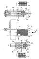
- FIG. 1 an embodiment of the invention is shown, and that shows the middle representation of a pressure-thrust system in which a preferably curved aircraft component 1 is clamped.
- the section AA shows a thrust beam 4 having arrangement for introducing the vertical thrust F Sv2 , wherein the hydraulic cylinder 6 representing detail X is shown enlarged in a separate illustration.
- the section BB shows a device for vertical application of force F Sv1 , which has the push bar 5 , the detail Y showing the hydraulic cylinders 7. These hydraulic cylinders are shown enlarged in a separate illustration.
- the upward-acting vertical thrust force F SV1 is applied by a force-controlled hydraulic cylinder 12 arranged above the pressure plate 3.
- the horizontally adjustable mounting of the hydraulic cylinder 12 takes place on the head frame, not shown in the drawing, which is arranged concentrically above the load introduction point of the aircraft component 1 to be tested.
- the introduction of force on the push bar 5 take two laterally guided, provided with force bars 8 tie rod 9.
- the tie rods 9 are rotatably supported via a respective force measuring rod 8 on the console 7a of the hydraulic cylinder 7 integrated in the push bar 5.
- the downwardly acting vertical thrust load F Sv2 is applied by two force-controlled hydraulic cylinders 13, which are articulated laterally on the push bar 4 and are provided with force measuring rods 10.
- the hydraulic cylinders 13 are supported on the pressure plate 3. They are articulated with their opposite ends on the force measuring rods 10 to the brackets 6a of the hydraulic cylinder 6 integrated in the push bar 4.
- the hydraulic cylinders described are in the 210 bar hydraulic system operated with force control.
- the above indicated Execution of the thrust introduction elements allows in Advantageously, the implementation of the required load introduction method at high thrust load.
Landscapes
- Physics & Mathematics (AREA)
- Health & Medical Sciences (AREA)
- Life Sciences & Earth Sciences (AREA)
- Chemical & Material Sciences (AREA)
- Analytical Chemistry (AREA)
- Biochemistry (AREA)
- General Health & Medical Sciences (AREA)
- General Physics & Mathematics (AREA)
- Immunology (AREA)
- Pathology (AREA)
- Investigating Strength Of Materials By Application Of Mechanical Stress (AREA)
- Testing Of Devices, Machine Parts, Or Other Structures Thereof (AREA)
Applications Claiming Priority (2)
| Application Number | Priority Date | Filing Date | Title |
|---|---|---|---|
| DE10344855 | 2003-09-26 | ||
| DE10344855A DE10344855B4 (de) | 2003-09-26 | 2003-09-26 | Druck-Schubanlage zur Einleitung von hohen Schublasten in ein vorzugsweise gewölbtes Flugzeugbauteil |
Publications (1)
| Publication Number | Publication Date |
|---|---|
| EP1524513A2 true EP1524513A2 (fr) | 2005-04-20 |
Family
ID=34353104
Family Applications (1)
| Application Number | Title | Priority Date | Filing Date |
|---|---|---|---|
| EP04022879A Withdrawn EP1524513A2 (fr) | 2003-09-26 | 2004-09-24 | Dispositif de poussée de pression pour l'introduction de fortes charges de pression dans une partie d'avion courbée |
Country Status (3)
| Country | Link |
|---|---|
| US (1) | US7155982B2 (fr) |
| EP (1) | EP1524513A2 (fr) |
| DE (1) | DE10344855B4 (fr) |
Cited By (9)
| Publication number | Priority date | Publication date | Assignee | Title |
|---|---|---|---|---|
| WO2007110067A3 (fr) * | 2006-03-29 | 2007-11-29 | Ima Materialforschung Und Anwe | Dispositif de contrôle pour coques de fuselage |
| CN102514723A (zh) * | 2011-11-18 | 2012-06-27 | 南京航空航天大学 | 一种气动载荷模拟装置 |
| CN104897485A (zh) * | 2015-03-19 | 2015-09-09 | 绍兴文理学院 | 全方位结构面倾斜剪切测试仪的多角度转换系统 |
| CN114486320A (zh) * | 2022-04-15 | 2022-05-13 | 中国飞机强度研究所 | 一种飞机测试用压力失衡紧急处理系统及其处理方法 |
| CN114577504A (zh) * | 2022-05-07 | 2022-06-03 | 中国飞机强度研究所 | 一种飞机测试的防冻压力调节系统及其调节方法 |
| CN115165596A (zh) * | 2022-07-29 | 2022-10-11 | 中国航发沈阳发动机研究所 | 一种大尺寸钛合金中介机匣强度试验装置 |
| CN115365299A (zh) * | 2022-09-22 | 2022-11-22 | 中重科技(天津)股份有限公司 | 一种带尾剪切装置 |
| CN118583672A (zh) * | 2024-08-07 | 2024-09-03 | 陕西陕飞锐方航空装饰有限公司 | 一种飞机航空附件制造用强度检测装置 |
| CN120101997A (zh) * | 2025-05-09 | 2025-06-06 | 长春汽车职业技术大学 | 一种汽车后挡风玻璃支架剪切力测试工装及其测试方法 |
Families Citing this family (24)
| Publication number | Priority date | Publication date | Assignee | Title |
|---|---|---|---|---|
| US7421906B2 (en) * | 2005-07-26 | 2008-09-09 | Airbus France | Apparatus for testing a fuselage structure having a longitudinal and circumferential curvature |
| US7426871B2 (en) * | 2005-07-26 | 2008-09-23 | Airbus France | Apparatus for testing a fuselage structure having a longitudinal and circumferential curvature |
| RU2303804C2 (ru) * | 2005-08-02 | 2007-07-27 | Федеральное государственное унитарное предприятие "Центральный аэрогидродинамический институт им. профессора Н.Е. Жуковского" (ФГУП "ЦАГИ") | Многоканальная система нагружения |
| US7389699B2 (en) * | 2005-10-13 | 2008-06-24 | The Boeing Company | Method and apparatus for testing shear strength of curved core material |
| FR2917827B1 (fr) * | 2007-06-25 | 2009-09-25 | Astrium Sas Soc Par Actions Si | Dispositif d'essai de panneaux structuraux. |
| US8024981B2 (en) * | 2008-04-21 | 2011-09-27 | Airbus Operations Gmbh | Device for test loading |
| US8286499B2 (en) | 2008-07-19 | 2012-10-16 | The Boeing Company | Method and apparatus for testing attachment joints |
| US8453515B2 (en) | 2010-09-03 | 2013-06-04 | UT-BaHelle, LLC | Apparatus and method for fatigue testing of a material specimen in a high-pressure fluid environment |
| EP2713151B1 (fr) * | 2012-09-28 | 2016-06-15 | Airbus Operations GmbH | Procédé de test et bancs d'essai |
| CN103454151A (zh) * | 2013-08-20 | 2013-12-18 | 中国商用飞机有限责任公司 | 压剪复合加载试验装置 |
| CN104697845B (zh) * | 2013-12-06 | 2017-06-06 | 中国飞机强度研究所 | 机身壁板静力/疲劳/损伤容限试验加载系统 |
| CN104691780A (zh) * | 2015-03-08 | 2015-06-10 | 西安电子科技大学 | 大跨度大挠度悬臂试验台的桁架结构 |
| CN109443952B (zh) * | 2018-12-07 | 2024-05-24 | 南京航空航天大学 | 一种t型接头剪切试验装置 |
| CN109900547B (zh) * | 2019-03-21 | 2024-05-07 | 镇江市建设工程质量检测中心有限公司 | 一种卧式压力机 |
| US11479371B1 (en) * | 2019-04-05 | 2022-10-25 | Northrop Grumman Systems Corporation | Load testing for flight control surface |
| CN110254748B (zh) * | 2019-05-27 | 2023-02-10 | 中国飞机强度研究所 | 一种接头-壁板结构静力压缩试验装置 |
| CN110220795B (zh) * | 2019-06-17 | 2024-05-03 | 河南交通职业技术学院 | 一种压力试验机 |
| CN110174316A (zh) * | 2019-06-21 | 2019-08-27 | 中国商用飞机有限责任公司北京民用飞机技术研究中心 | 一种复合材料c型梁弯曲和剪切耦合加载装置 |
| CN111595699B (zh) * | 2020-06-18 | 2022-02-22 | 中国飞机强度研究所 | 一种平直壁板压剪试验装置 |
| CN112730024B (zh) * | 2020-12-07 | 2022-05-17 | 川南城际铁路有限责任公司 | 一种测试岩石材料压缩与剪切性能的一体化装置 |
| CN113218650B (zh) * | 2021-06-04 | 2023-12-22 | 中国飞机强度研究所 | 一种起落架强度试验垂向载荷加载装置 |
| CN114876672B (zh) * | 2022-04-30 | 2023-10-13 | 西安航天动力测控技术研究所 | 固体火箭发动机安全机构盖体剪切极限测量装置及方法 |
| CN118857951B (zh) * | 2024-07-15 | 2025-09-05 | 石家庄铁道大学 | 聚氨酯胶结道砟接触力学性能测试装置及方法 |
| CN119985133B (zh) * | 2025-04-11 | 2025-11-25 | 山东立鼎测绘有限公司 | 一种测量工程测绘用岩土检测装置 |
Family Cites Families (9)
| Publication number | Priority date | Publication date | Assignee | Title |
|---|---|---|---|---|
| FR550130A (fr) * | 1921-08-13 | 1923-02-27 | Air Liquide | Procédé d'enlèvement rapide des dépôts solides formés par le froid dans les échangeurs de températures servant à la purification frigorifique des gaz |
| CH374221A (de) * | 1958-11-14 | 1963-12-31 | Losenhausenwerk Duesseldorfer | Prüfanlage für grössere Bauteile, vorzugsweise Flugzeugzellen |
| US4478086A (en) * | 1983-01-07 | 1984-10-23 | Mts Systems Corporation | Load frame crosshead construction |
| US4864866A (en) * | 1988-04-11 | 1989-09-12 | Hardy Raymond D | Mechanical property testing machine |
| US5677494A (en) * | 1996-03-05 | 1997-10-14 | Mcdonnell Douglas Corporation | Method for high strain-rate testing of specimens |
| US5712431A (en) * | 1996-05-01 | 1998-01-27 | Endura-Tec Systems Corporation | Device and method for testing the shear response of a material in response to an applied force |
| DE19727754A1 (de) * | 1997-07-01 | 1999-01-07 | Wpm Werkstoffpruefmaschinen Gm | Vorrichtung zum Einspannen und Prüfen von Prüfkörpern |
| US6467357B1 (en) * | 2000-10-25 | 2002-10-22 | Geostar Corp. | Clamping apparatus and method for testing strength characteristics of sheets |
| US6598486B2 (en) * | 2001-05-21 | 2003-07-29 | Enduratec Systems Corporation | Portable device for testing the shear response of a material in response to a repetitive applied force |
-
2003
- 2003-09-26 DE DE10344855A patent/DE10344855B4/de not_active Expired - Fee Related
-
2004
- 2004-09-24 EP EP04022879A patent/EP1524513A2/fr not_active Withdrawn
- 2004-09-27 US US10/951,920 patent/US7155982B2/en not_active Expired - Fee Related
Cited By (14)
| Publication number | Priority date | Publication date | Assignee | Title |
|---|---|---|---|---|
| US7624695B2 (en) | 2006-03-29 | 2009-12-01 | Ima Materialforschung Und Anwendungstechnik Gmbh | Testing device for hull shells |
| WO2007110067A3 (fr) * | 2006-03-29 | 2007-11-29 | Ima Materialforschung Und Anwe | Dispositif de contrôle pour coques de fuselage |
| CN102514723A (zh) * | 2011-11-18 | 2012-06-27 | 南京航空航天大学 | 一种气动载荷模拟装置 |
| CN104897485A (zh) * | 2015-03-19 | 2015-09-09 | 绍兴文理学院 | 全方位结构面倾斜剪切测试仪的多角度转换系统 |
| CN104897485B (zh) * | 2015-03-19 | 2017-07-28 | 绍兴文理学院 | 全方位结构面倾斜剪切测试仪的多角度转换系统 |
| CN114486320B (zh) * | 2022-04-15 | 2022-06-24 | 中国飞机强度研究所 | 一种飞机测试用压力失衡紧急处理系统及其处理方法 |
| CN114486320A (zh) * | 2022-04-15 | 2022-05-13 | 中国飞机强度研究所 | 一种飞机测试用压力失衡紧急处理系统及其处理方法 |
| CN114577504A (zh) * | 2022-05-07 | 2022-06-03 | 中国飞机强度研究所 | 一种飞机测试的防冻压力调节系统及其调节方法 |
| CN114577504B (zh) * | 2022-05-07 | 2022-07-12 | 中国飞机强度研究所 | 一种飞机测试的防冻压力调节系统及其调节方法 |
| CN115165596A (zh) * | 2022-07-29 | 2022-10-11 | 中国航发沈阳发动机研究所 | 一种大尺寸钛合金中介机匣强度试验装置 |
| CN115165596B (zh) * | 2022-07-29 | 2024-05-17 | 中国航发沈阳发动机研究所 | 一种大尺寸钛合金中介机匣强度试验装置 |
| CN115365299A (zh) * | 2022-09-22 | 2022-11-22 | 中重科技(天津)股份有限公司 | 一种带尾剪切装置 |
| CN118583672A (zh) * | 2024-08-07 | 2024-09-03 | 陕西陕飞锐方航空装饰有限公司 | 一种飞机航空附件制造用强度检测装置 |
| CN120101997A (zh) * | 2025-05-09 | 2025-06-06 | 长春汽车职业技术大学 | 一种汽车后挡风玻璃支架剪切力测试工装及其测试方法 |
Also Published As
| Publication number | Publication date |
|---|---|
| DE10344855B4 (de) | 2005-08-04 |
| US7155982B2 (en) | 2007-01-02 |
| DE10344855A1 (de) | 2005-05-04 |
| US20050109118A1 (en) | 2005-05-26 |
Similar Documents
| Publication | Publication Date | Title |
|---|---|---|
| DE10344855B4 (de) | Druck-Schubanlage zur Einleitung von hohen Schublasten in ein vorzugsweise gewölbtes Flugzeugbauteil | |
| EP3874248B1 (fr) | Procédé et dispositif d'essai pour soumettre à essai des pales de rotor | |
| EP2741068B1 (fr) | Banc d'essai pour une pale de rotor, dispositif doté d'un tel banc d'essai et procédé de fonctionnement d'un tel banc d'essai | |
| EP2905108B1 (fr) | Châssis d'une machine | |
| EP4209656B1 (fr) | Dispositif modulaire de coffrage de tunnel | |
| DE102012025649A1 (de) | Prüfstand für ein Rotorblatt, Anordnung mit einem derartigen Prüfstand und Verfahren zum Betreiben eines derartigen Prüfstands | |
| DE2239553B2 (de) | Zug- und/oder druckpruefmaschine | |
| EP0669686A1 (fr) | Structure de suspension pour un appareil | |
| DE1956889A1 (de) | Vorrichtung zur Korrektur der Durchbiegung eines horizontalen Halterungselementes einer Werkzeugmaschine | |
| EP0624411A1 (fr) | Procédé pour plier des tôles et presse à plier pour la mise en oeuvre du procédé | |
| DE60032276T2 (de) | Einbauverfahren eines Wiegebrückebauwerks und Anordnung zur Verwirklichung dieses Verfahrens | |
| DE19727754A1 (de) | Vorrichtung zum Einspannen und Prüfen von Prüfkörpern | |
| EP1941956A1 (fr) | Presse de pliage destinée à plier une tôle lors de la fabrication d'un tuyau | |
| EP1597019A1 (fr) | Revetement de protection pour la zone de travail d'une machine-outil | |
| DE19602712A1 (de) | Verfahren und Simulationsvorrichtung zur Ermittlung von experimentellen Daten zur Qualitätsbewertung von Werkzeugträgern | |
| EP3415890A1 (fr) | Banc d'essai pour un raccord d'articulation de pas | |
| DE2241976A1 (de) | Vorrichtung zum pruefen von lasttragmitteln und lastaufnahmemitteln | |
| EP0187784A1 (fr) | Dispositif d'essai pour elements en forme de barre, en particulier un segment d'ossature porteuse d'un ouvrage d'art. | |
| DE10231771B4 (de) | Vorrichtung zur Auflagerung von Kranbahnen | |
| DE2719103A1 (de) | Vorrichtung zum abspannen von hochspannungsfreileitungen | |
| DE1552955C (de) | Richtanlage fur Fahrzeugrahmen | |
| DE102021118550A1 (de) | Vorrichtung zum Bearbeiten eines Werkstücks | |
| DE919522C (de) | Ringausbau fuer Schaechte, insbesondere Blindschaechte, Gesenke u. dgl. und Verfahren zu seiner Herstellung | |
| DE2609546C2 (de) | Einrichtung zum Abtrennen der Düsenrohre bzw. Anschließen derselben an eine Winddüse | |
| DE102014018441A1 (de) | Prüfvorrichtung zum Überprüfen wenigstens einer Blattfeder |
Legal Events
| Date | Code | Title | Description |
|---|---|---|---|
| PUAI | Public reference made under article 153(3) epc to a published international application that has entered the european phase |
Free format text: ORIGINAL CODE: 0009012 |
|
| AK | Designated contracting states |
Kind code of ref document: A2 Designated state(s): AT BE BG CH CY CZ DE DK EE ES FI FR GB GR HU IE IT LI LU MC NL PL PT RO SE SI SK TR |
|
| AX | Request for extension of the european patent |
Extension state: AL HR LT LV MK |
|
| STAA | Information on the status of an ep patent application or granted ep patent |
Free format text: STATUS: THE APPLICATION IS DEEMED TO BE WITHDRAWN |
|
| 18D | Application deemed to be withdrawn |
Effective date: 20150331 |